EP0424902A2 - Méthode de détection de fuites et de contrôle de qualité non destructif des joints de matériaux de couverture pour toitures - Google Patents
Méthode de détection de fuites et de contrôle de qualité non destructif des joints de matériaux de couverture pour toitures Download PDFInfo
- Publication number
- EP0424902A2 EP0424902A2 EP90120384A EP90120384A EP0424902A2 EP 0424902 A2 EP0424902 A2 EP 0424902A2 EP 90120384 A EP90120384 A EP 90120384A EP 90120384 A EP90120384 A EP 90120384A EP 0424902 A2 EP0424902 A2 EP 0424902A2
- Authority
- EP
- European Patent Office
- Prior art keywords
- seam
- unbonded
- created
- providing
- void area
- Prior art date
- Legal status (The legal status is an assumption and is not a legal conclusion. Google has not performed a legal analysis and makes no representation as to the accuracy of the status listed.)
- Withdrawn
Links
Images

Classifications
-
- G—PHYSICS
- G01—MEASURING; TESTING
- G01N—INVESTIGATING OR ANALYSING MATERIALS BY DETERMINING THEIR CHEMICAL OR PHYSICAL PROPERTIES
- G01N19/00—Investigating materials by mechanical methods
- G01N19/04—Measuring adhesive force between materials, e.g. of sealing tape, of coating
Definitions
- This invention deals with a method of quality control testing and leak detection for roofing seams.
- the method is non-destructive and can be applied to already existing old roof seams, newly installed roof seams, or seams in factory manufactured roofing materials before they are installed in a roofing system.
- roof surfaces generally are multi-layered, that is, they generally have in combination a roof supporting structure which is surmounted by a deck, and various layers of water impermeable membranes, thermal insulation and a ballast layer to assist in holding the entire roof from being blown away.
- Single ply roof membranes of elastomeric or thermoplastic materials are seamed by bonding the roof materials together using sheets of varying widths and lengths to form an integrated membrane for covering the roof surface.
- the quality and integrity of the membrane is dependent on the quality of the seams and one of the largest problems in producing such large flat roofs is the quality of the bonds in the seams that are provided in the single ply membranes that are used as the water impermeable layers in such roofs. This problem is of continual concern to the industry because the leakage problem is so severe. It causes degradation of other roof components and such leaks are difficult to locate.
- the weatherable and essentially inert materials that are used for the single ply roofing materials are known to have multiple problems with bonding to themeselves and to each other, and consequently, the seams created from these materials are an unknown entity.
- practitioners experience false welds or bonds due to moisture on the surface of the material.
- Welding guns may be cold when they were thought to be heat sealing. Marks used for stopping and starting the bonding may have been missed and a problem with the use of reinforcement, which boils off and blisters the polymeric materials and ruptures the bonds are all common faults in the application of roofs.
- Caulk is sometimes used for protecting such seams and in a number of cases becomes the only bonded and sealed portion of such seams but is not considered to be a very effective solution to a fully bonded seam area.
- T-peel test is a very simple stress/strain test wherein two sides of a lapped roofing material are put into the vertical holding jigs of a tensile testing machine and pulled at an angle of 180° from each other, and at a specific rate.
- Such machines are manufactured by the Instron Corporation and are hence sometimes called the "Instron test". The machines are designed such that the loads required to pull the laps apart are directly recorded along with the width of the sample so that the load/area normally reported in units of pound/inch may be observed.
- the present invention therefore deals with solutions to the problems of quality control testing of the seams of a single ply roofing assembly to quickly and accurately determine if the seams have the strength to hold up under normal weathering circumstances. It also applys to a novel leak detection method for such seams, both methods being non-destructive to the roof seam.
- the instant invention in one particular therefore comprises a method of non-destructive testing comprising: (A) overlapping at least two pieces of roofing material in preparation for creating a seam; (B) bonding the overlapped roofing materials at approximately the leading edge of the bottommost roofing material; (C) bonding the overlapped roofing materials at approximately the leading edge of the uppermost roofing material approximately parallel to the bond created in (B), thereby creating a seam; (D) bonding the overlapped roofing materials at least at each of the terminal ends of the seam created, thereby forming an unbonded void area between the bond created in (B), the bond created in (C), the bonds created in (D), and the overlapped roofing materials; (E) providing a gas injection means at any point along the seam length to be tested; (F) injecting a gas into the unbonded void area to create a known pressure within the unbonded void area; (G) determining the bond area and the bond strength for the bonded seams.
- the instant invention also comprises a method for testing factory manufactured double seamed roofing material and that method is a method of non-destructive testing comprising: (A) providing a double seamed overlapped roofing material; (B) bonding the double seamed overlapped roofing materials at least at each of the terminal ends of the seam created, thereby forming an unbonded void area between the bonds provided by (A), the bond created in (B), and the overlapped roofing materials; (C) providing a gas injection means at any point along the seam length to be tested; (D) injecting a gas into the unbonded void area to create a known pressure within the unbonded void area; (E) determining the bond area and bond strength for the bonded seams.
- the method comprises a system of non-destructive testing in seamed roofing, wherein a small spot or short length of roofing seam can be tested, without testing the entire length of the seam, the method comprising (A) overlapping at least two pieces of roofing material in preparation for creating a seam; (B) bonding the overlapped roofing materials at approximately the leading edge of the bottommost roofing material; (C) bonding the overlapped roofing materials at approximately the leading edge of the uppermost roofing material approximately parallel to the bond created in (B), thereby creating a seam; (D) bonding the overlapped roofing materials at least at each of the terminal ends of the seam created, thereby forming an unbonded void area between the bond created in (B), the bond created in (C), the bonds created in (D), and the overlapped roofing materials; (E) providing a gas injection means at any point along the seam length to be tested; (F) providing a weighted air barrier on a seam length to be tested; (G) injecting a gas into the unbonded void area to create
- Yet another aspect of this invention is a quality control check for commercial, factory manufactured, seamed roofing material, before the material is used in a roof system, wherein the method is a non-destructive testing method comprising: (A) providing a double seamed overlapped roofing material; (B) bonding the double seamed overlapped roofing materials at least at each of the terminal ends of the seam created, thereby forming an unbonded void area between the bonds provided by (A), the bond created in (B), and the overlapped roofing materials; (C) providing a gas injection means at any point along the seam length to be tested; (D) providing a weighted air barrier on the seam length to be tested; (E) injecting a gas into the unbonded void area to create a known pressure within the unbonded void area; (F) determining the bond area and bond strength for the bonded seams.
- Still another aspect of this invention is a method of testing the strength of and obtaining leak detection of single seams in roofing membranes.
- this invention also deals with a simple method of testing single seamed i.e. single bonded roofing materials, whether or not the seams are manufactured on the roof surface, or whether they are pre-manufactured off the roof.
- a simple method uses in part, the method described above for determining leaks in spot checks for short lengths of seams utilizing the weighted air barrier technique.
- a double seam roof material i.e. a double bonded roof material of this invention, wherein the material is bonded at 5 and also at 6.
- a single seam roof material would be similar, except the bond at 5 would not exist, the bottommost layer simply being tacked or nailed onto the deck surface and the topmost layer being overlapped and bonded only at 6.
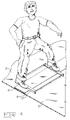
- weighted air barrier be modified at L such that L also contacts and compresses the surface of the topmost layer thereby creating an air barrier between L and the iron bars where the laborer has placed his feet, the bond 6 acting as the fourth barrier edge.
- this weighted air barrier has been illustrated using the weight of a workman to hold down the weighted air barrier, but it is within the scope of this invention, and contemplated by the inventor herein that any manner of weight can be used, for example, bricks, blocks, additional iron, weighted wheelbarrows, and the like.
- this invention comprises a method of leak detection in roof systems comprising (A) overlapping at least two pieces of roofing material in preparation for creating a seam; (B) bonding the overlapped roofing materials at approximately the leading edge of the bottommost roofing material; (C) bonding the overlapped roofing materials at approximately the leading edge of the uppermost roofing material approximately parallel to the bond created in (B), thereby creating a seam; (D) bonding the overlapped roofing materials at least at each of the terminal ends of the seam created, thereby forming an unbonded void area between the bond created in (B), the bond created in (C), the bonds created in (D), and the overlapped roofing materials; (E) providing a gas injection means at any point along the seam length to be tested; (F) injecting a detectable gas into the unbonded void area to create a pressure within the unbonded void area; (G) determining the points of leakage of the detectable gas along the seam.
- this invention deals with a method of detecting leaks in roofing material seams, before the roofing material in used in a roof system, the method comprising (A) providing a seamed overlapped roofing material; (B) bonding the double seamed overlapped roofing materials at least at each of the terminal ends of the seam created, thereby forming an unbonded void area between the bonds provided by (A), the bond created in (B), and the overlapped roofing materials; (C) providing a gas injection means at any point along the seam length to be tested; (D) injecting a detectable gas into the unbonded void area to create a pressure within the unbonded void area; (E) determining the points of leakage of the detectable gas along the seam.
- Figure 1 a sectional side view of an overlapped seam 1 created by the overlapping of two adjacent pieces of single ply roofing material, the bottommost layer being illustrated as 3 and the uppermost layer being illustrated as 2.
- the materials of construction may be the same kind of materials or they may be different from each other.
- the preparations for the quality control check of the seams begins with the creation of the seams, it being understood for purposes of this disclosure that only one bond seams are normally used in single ply roofing and that the creation of the second bonded area is not normally required in single ply roofing, nor is it necessarily denoted as a seam, and that the creation of the second bonded area is for the purpose of carrying out one aspect of the method of this invention.
- the bonded areas are designated as "seams", irrespective of their eventual use in this inventive method.
- the bottommost layer 3 is laid on the roof structure 4 and the uppermost layer 2 is lapped over the bottommost layer 3.
- This overlap usually consists of an overlap in the range of 4 to 8 inches depending on the type of material used and the type of roof being constructed.
- the leading edge 5 of the bottommost layer 3 is either glued or fused, depending on the type of single ply material being used, to the uppermost layer 2.
- the uppermost layer 2 is laid down on the bottommost layer 3 and bonded at the leading edge 6 of the uppermost layer 2.
- a further means of providing an unbonded surface at the indicated area 7 is to construct the seam with a non-fusible or non-glueable interlayer between the two layers of single ply materials as the roof is being assembled. This more or less guarantees a certain amount of non-bonded area in the seam.
- the roof coverings are also bonded around the outside edges of the roof, thereby creating long seams also having bonds at each of their ends.
- This inventive method can be used on almost any length of seam, from several inches to several hundred feet in length, and it can be used for testing irregular shaped seams, such as patches, corner assemblies, edges, and the like.
- irregular shapes do not have to be double bonded however, as it is obvious that they would generally have single seams about their outside edges, for example, it is common to use saucer shaped patches made of single ply roofing material to cover holddown devices on roof surfaces to prevent leaking through or around such devices. These saucer shaped patches are laid down over the holddown devices and their outer edges bonded to the existing single ply roofing material. For purposes of this invention, an entire seam length can be tested at one time.
- the instant invention is not limited to the use of the weighted air barrier on single seamed materials.
- a weighted air barrier can also be used.
- the weighted air barrier approach has practical utility as the barrier is transportable, is essentially light weight, can he weighted by the body weight of the workman testing the seam, or it can be weighted by cement blocks, iron plates, or the like, it being understood that the configuration of the barrier is not critical and that it can be rectangular, square, circular, or the like in configuration.
- a means for injecting air into the unbonded void area between the seams can be a small valve, such as a basketball inflating valve, which can be attached to a gas source, such as compressed air, or hand pumped air.
- the air is injected into the void and the pressure created by the forced air forms a cylindrical or elliptical shape 8 out of the materials that are seamed, and trapped by the air barriers, such as that shown in Figure 2. If the conventional overlap widths and seam widths are adhered to, then the void will have the approximate configuration of a bicycle tire.
- the shape of the seam created by pressurizing of the void can be readily observed and as shown in Figure 3, gives an irregular pattern 9 and 9′ against both sides of the formed cylindrical or irregular shape 8.
- the shape thus created can be traced by a colored pencil or chalk on the upper surface of the roofing material to show the width and the outline of the bonding of each side of the seams.
- By adjusting the pressure within the trapped area there is created a tensile stress on the walls of the cylindrical shape.
- By examining the interface between the bottom and top materials it can be seen that essentially the "T" peel arrangement is developed in situ.
- the pressure within the system can be converted to loads measured in pounds per inch of width.
- the quality control test can be run to a level of about 70 to 80 percent of the desired testing strength and indicated as being acceptable or not acceptable. If not acceptable, the roof can be repaired immediately at that point.
- the second formula for cylinders refers to the load in the transverse direction. It can be seen that the load in pounds per square inch is equal to the pressure in psi times the diameter in inches divided by a constant of 4 and divided by the thickness of the material being tested. By deleting the thickness of the material, that is, taking the pressure results times the thickness in inches, the units are transferred to pounds per inch of width. Therefore the simplest formula would be: the load in pounds per inch of width is directly proportional to the pressure times the diameter divided by 4.
- the material has the capability of developing a "T" strength of 40 pounds per inch of width and is designated to test passing of 30 pounds per inch of width, using a diameter of one inch, which is equal to the width of the unbonded space between the two seamed areas the pressure would be as high 120 psi. As the diameter increases with rupturing of the bond, the stress in pounds per inch goes up directly and proportionally.
- tests were conducted on a known commercial roofing membrane, Durolast. The tests were run on field and factory seams to establish the amount of T-pull necessary to break the membrane weld. To confirm the test results, T-pull tests with established weight settings were used to establish standard values of the strength of the seams.
- a second testing method was used designated for purposes of this disclosure, the "angle iron closed track test".
- An angle iron closed track measuring 6 inches by 24 inches was designed for further use in testing of T-pull seams in the field. This allowed an inspector to test any seams at random on a finished roof system.
- This closed track can be used in making its own air pockets at any distance desired by the field inspector within the confines of less than one inch to 24 inches.
- pressure By applying pressure from an air pressure tank, the pressure can be set knowing the area of air pocket made. The pressure can then be set to the requirements of testing the seams without breaking them or finding out that the seam is weak.
- the amount of pressure applied by the device is dependent on the weight applied. A one hundred eighty pound man using it can use approximately 6 to 8 pounds of pressure.
Landscapes
- Physics & Mathematics (AREA)
- Health & Medical Sciences (AREA)
- Life Sciences & Earth Sciences (AREA)
- Chemical & Material Sciences (AREA)
- Analytical Chemistry (AREA)
- Biochemistry (AREA)
- General Health & Medical Sciences (AREA)
- General Physics & Mathematics (AREA)
- Immunology (AREA)
- Pathology (AREA)
- Examining Or Testing Airtightness (AREA)
Applications Claiming Priority (2)
| Application Number | Priority Date | Filing Date | Title |
|---|---|---|---|
| US426213 | 1982-10-04 | ||
| US07/426,213 US5143568A (en) | 1989-10-25 | 1989-10-25 | Method for leak detection and non-destructive quality control testing for roofing seams |
Publications (2)
| Publication Number | Publication Date |
|---|---|
| EP0424902A2 true EP0424902A2 (fr) | 1991-05-02 |
| EP0424902A3 EP0424902A3 (en) | 1992-03-18 |
Family
ID=23689817
Family Applications (1)
| Application Number | Title | Priority Date | Filing Date |
|---|---|---|---|
| EP19900120384 Withdrawn EP0424902A3 (en) | 1989-10-25 | 1990-10-24 | Method for leak detection and non-destructive quality control testing for roofing seams |
Country Status (3)
| Country | Link |
|---|---|
| US (1) | US5143568A (fr) |
| EP (1) | EP0424902A3 (fr) |
| CA (1) | CA2028420A1 (fr) |
Cited By (1)
| Publication number | Priority date | Publication date | Assignee | Title |
|---|---|---|---|---|
| FR3076350A1 (fr) * | 2017-12-28 | 2019-07-05 | Compagnie Plastic Omnium | Procede de controle d'un procede de collage de deux pieces |
Families Citing this family (5)
| Publication number | Priority date | Publication date | Assignee | Title |
|---|---|---|---|---|
| SE500852C2 (sv) * | 1992-01-29 | 1994-09-19 | Mataki Ab | Sätt och anordning för läckagetest av med tätskikt klädda yttertak eller bjälklag |
| US5674333A (en) * | 1992-10-23 | 1997-10-07 | Denco, Inc. | Total containment welding of plastic tubes |
| US6296006B1 (en) * | 1998-03-10 | 2001-10-02 | Koppl Company, Inc. | System and method for sealing leaks in vessels |
| US6537402B2 (en) | 2001-07-26 | 2003-03-25 | Omnova Solutions Inc. | Membrane welding apparatus including a visual seam marker |
| FR3070488B1 (fr) * | 2017-08-28 | 2020-05-29 | Icopal Sas | Procede de controle de l'etancheite d'un revetement bitumineux et membrane ou geomembrane d'etancheite bitumineuse pour sa mise en oeuvre |
Family Cites Families (4)
| Publication number | Priority date | Publication date | Assignee | Title |
|---|---|---|---|---|
| CH655343A5 (de) * | 1981-10-06 | 1986-04-15 | Ernst Ammann Ag Wallenwil | Vorrichtung zum ueberbruecken der fuge zwischen zwei teilen einer dacheindeckung und verwendung derselben. |
| US4723109A (en) * | 1985-04-26 | 1988-02-02 | Sheahan James P | Hold down device |
| US4748847A (en) * | 1987-05-26 | 1988-06-07 | Sheahan James P | Non-electrical leak detection method |
| US4768376A (en) * | 1987-06-17 | 1988-09-06 | International Paper Company | Polyethylene coating adhesion testing |
-
1989
- 1989-10-25 US US07/426,213 patent/US5143568A/en not_active Expired - Fee Related
-
1990
- 1990-10-24 CA CA002028420A patent/CA2028420A1/fr not_active Abandoned
- 1990-10-24 EP EP19900120384 patent/EP0424902A3/en not_active Withdrawn
Cited By (1)
| Publication number | Priority date | Publication date | Assignee | Title |
|---|---|---|---|---|
| FR3076350A1 (fr) * | 2017-12-28 | 2019-07-05 | Compagnie Plastic Omnium | Procede de controle d'un procede de collage de deux pieces |
Also Published As
| Publication number | Publication date |
|---|---|
| US5143568A (en) | 1992-09-01 |
| CA2028420A1 (fr) | 1991-04-26 |
| EP0424902A3 (en) | 1992-03-18 |
Similar Documents
| Publication | Publication Date | Title |
|---|---|---|
| JP5307890B2 (ja) | 構造用シールの密封性をチェックする方法および装置 | |
| JP2655232B2 (ja) | 漏電探知を容易にして屋外貯液場所をライニングする方法及び同ライナー | |
| US6688338B2 (en) | Secondary containment system for pipelines | |
| CN101260809B (zh) | 背面铺贴ab扣的自粘型防水板的施工工艺 | |
| US4074492A (en) | Prefabricated watertight structural system | |
| US5143568A (en) | Method for leak detection and non-destructive quality control testing for roofing seams | |
| US3481087A (en) | Weatherproofing system and envelope panel therefor | |
| Reddy et al. | A comprehensive literature review of liner failures and longevity | |
| KR20050050341A (ko) | 방수재 시험장치 | |
| JP3910256B2 (ja) | 遮水シート接合部の欠陥検査方法 | |
| JP2008107338A (ja) | 遮水シート接合部の検査方法 | |
| JP3810512B2 (ja) | 遮水シート接合部の欠陥検査方法 | |
| Rigo et al. | Test standards and their classification | |
| JPH11277027A (ja) | 遮水シートの接合部構造および遮水シート接合部の検査方法 | |
| JPH02136414A (ja) | 遮水シートにおける欠損部の検知方法 | |
| Strong et al. | Standards development for impermeable, constructible, and durable waterproofing | |
| Elton et al. | Geomembrane research needs | |
| JPH0480452A (ja) | 防水シート及び接合部の検査方法 | |
| Gränne | Air and water tightness in building envelopes-evaluation of methods for quality assurance | |
| Kai et al. | Application of Geomembrane on the Dam of Concrete Face in a Certain Hydropower Station Project | |
| Mollard et al. | Geomembrane landfill liners in the real world | |
| CN116517030A (zh) | 一种油库罐区防渗铺设工艺 | |
| Geomembranes | Factory Fabricated Compounded 0.25 to 1.52 mm (10 to 60 mil) Thickness Unsupported Geomembranes | |
| Bogdanoff et al. | Concept for gas storage by sealing rock caverns with thin plastic and rubber | |
| CN120026662A (zh) | 一种防水系统 |
Legal Events
| Date | Code | Title | Description |
|---|---|---|---|
| PUAI | Public reference made under article 153(3) epc to a published international application that has entered the european phase |
Free format text: ORIGINAL CODE: 0009012 |
|
| AK | Designated contracting states |
Kind code of ref document: A2 Designated state(s): CH DE FR GB LI SE |
|
| PUAL | Search report despatched |
Free format text: ORIGINAL CODE: 0009013 |
|
| AK | Designated contracting states |
Kind code of ref document: A3 Designated state(s): CH DE FR GB LI SE |
|
| STAA | Information on the status of an ep patent application or granted ep patent |
Free format text: STATUS: THE APPLICATION HAS BEEN WITHDRAWN |
|
| 18W | Application withdrawn |
Withdrawal date: 19920521 |