EP0424627A2 - Elektrochemische Wickelzelle - Google Patents
Elektrochemische Wickelzelle Download PDFInfo
- Publication number
- EP0424627A2 EP0424627A2 EP90115947A EP90115947A EP0424627A2 EP 0424627 A2 EP0424627 A2 EP 0424627A2 EP 90115947 A EP90115947 A EP 90115947A EP 90115947 A EP90115947 A EP 90115947A EP 0424627 A2 EP0424627 A2 EP 0424627A2
- Authority
- EP
- European Patent Office
- Prior art keywords
- nonwoven
- separator
- nonwoven fabric
- cell
- winding
- Prior art date
- Legal status (The legal status is an assumption and is not a legal conclusion. Google has not performed a legal analysis and makes no representation as to the accuracy of the status listed.)
- Withdrawn
Links
Images
Classifications
-
- H—ELECTRICITY
- H01—ELECTRIC ELEMENTS
- H01M—PROCESSES OR MEANS, e.g. BATTERIES, FOR THE DIRECT CONVERSION OF CHEMICAL ENERGY INTO ELECTRICAL ENERGY
- H01M50/00—Constructional details or processes of manufacture of the non-active parts of electrochemical cells other than fuel cells, e.g. hybrid cells
- H01M50/40—Separators; Membranes; Diaphragms; Spacing elements inside cells
- H01M50/409—Separators, membranes or diaphragms characterised by the material
- H01M50/44—Fibrous material
-
- H—ELECTRICITY
- H01—ELECTRIC ELEMENTS
- H01M—PROCESSES OR MEANS, e.g. BATTERIES, FOR THE DIRECT CONVERSION OF CHEMICAL ENERGY INTO ELECTRICAL ENERGY
- H01M50/00—Constructional details or processes of manufacture of the non-active parts of electrochemical cells other than fuel cells, e.g. hybrid cells
- H01M50/40—Separators; Membranes; Diaphragms; Spacing elements inside cells
- H01M50/409—Separators, membranes or diaphragms characterised by the material
- H01M50/411—Organic material
- H01M50/414—Synthetic resins, e.g. thermoplastics or thermosetting resins
- H01M50/417—Polyolefins
-
- H—ELECTRICITY
- H01—ELECTRIC ELEMENTS
- H01M—PROCESSES OR MEANS, e.g. BATTERIES, FOR THE DIRECT CONVERSION OF CHEMICAL ENERGY INTO ELECTRICAL ENERGY
- H01M50/00—Constructional details or processes of manufacture of the non-active parts of electrochemical cells other than fuel cells, e.g. hybrid cells
- H01M50/40—Separators; Membranes; Diaphragms; Spacing elements inside cells
- H01M50/489—Separators, membranes, diaphragms or spacing elements inside the cells, characterised by their physical properties, e.g. swelling degree, hydrophilicity or shut down properties
-
- H—ELECTRICITY
- H01—ELECTRIC ELEMENTS
- H01M—PROCESSES OR MEANS, e.g. BATTERIES, FOR THE DIRECT CONVERSION OF CHEMICAL ENERGY INTO ELECTRICAL ENERGY
- H01M2300/00—Electrolytes
- H01M2300/0017—Non-aqueous electrolytes
- H01M2300/0025—Organic electrolyte
-
- Y—GENERAL TAGGING OF NEW TECHNOLOGICAL DEVELOPMENTS; GENERAL TAGGING OF CROSS-SECTIONAL TECHNOLOGIES SPANNING OVER SEVERAL SECTIONS OF THE IPC; TECHNICAL SUBJECTS COVERED BY FORMER USPC CROSS-REFERENCE ART COLLECTIONS [XRACs] AND DIGESTS
- Y02—TECHNOLOGIES OR APPLICATIONS FOR MITIGATION OR ADAPTATION AGAINST CLIMATE CHANGE
- Y02E—REDUCTION OF GREENHOUSE GAS [GHG] EMISSIONS, RELATED TO ENERGY GENERATION, TRANSMISSION OR DISTRIBUTION
- Y02E60/00—Enabling technologies; Technologies with a potential or indirect contribution to GHG emissions mitigation
- Y02E60/10—Energy storage using batteries
-
- Y—GENERAL TAGGING OF NEW TECHNOLOGICAL DEVELOPMENTS; GENERAL TAGGING OF CROSS-SECTIONAL TECHNOLOGIES SPANNING OVER SEVERAL SECTIONS OF THE IPC; TECHNICAL SUBJECTS COVERED BY FORMER USPC CROSS-REFERENCE ART COLLECTIONS [XRACs] AND DIGESTS
- Y02—TECHNOLOGIES OR APPLICATIONS FOR MITIGATION OR ADAPTATION AGAINST CLIMATE CHANGE
- Y02P—CLIMATE CHANGE MITIGATION TECHNOLOGIES IN THE PRODUCTION OR PROCESSING OF GOODS
- Y02P70/00—Climate change mitigation technologies in the production process for final industrial or consumer products
- Y02P70/50—Manufacturing or production processes characterised by the final manufactured product
Definitions
- the invention relates to an electrochemical winding cell, in particular lithium winding cell and in particular Li-MnO2 winding cell, with a separator arranged between the electrodes (anode, cathode) made of a nonwoven fabric.
- the separator which usually consists of a nonwoven fabric and / or a microporous film, is a problem with such high-performance cells in a wound construction.
- the thickness of the cathode increases during the discharge, this increase in volume having to be partially absorbed by the separator so that the cell can be safely discharged and no short circuits occur. For this reason, the separator in Li-MnO2 winding cells cannot be as thin as desired.
- a major disadvantage in the case of relatively thick nonwovens made from fibers with customary diameters of greater than 20 ⁇ m is, however, that the internal resistance of the winding cell is increased in such a way that high discharge currents are no longer possible. About that In addition, volume is lost for the active electrode mass due to a thick nonwoven fabric, so that the result is a loss of capacity of the winding cell.
- the object of the invention is to provide an improved separator made of a nonwoven fabric for an electrochemical winding cell, in particular a lithium winding cell and in particular a Li-MnO2 winding cell.
- the separator is a single-layer nonwoven fabric made of polypropylene fibers welded together with the following technical data: -
- the diameter of the polypropylene fibers is 5 to 10 microns -
- the basis weight of the nonwoven is 20 to 60 g ⁇ m2 -
- the thickness of the nonwoven fabric is 0.1 to 0.4 mm, preferably 0.2 to 0.3 mm -
- the air permeability of the nonwoven is 400 to 600 dm3 ⁇ s ⁇ 1 ⁇ m2 (at 1 mbar pressure difference).
- the nonwoven preferably has the following technical data: - The fiber diameter is approx. 8 ⁇ m - The mass per unit area of the nonwoven is approx. 40 g ⁇ m2 - The thickness of the nonwoven is approximately 0.26 mm - The air permeability of the nonwoven is about 500 dm3 ⁇ s ⁇ 1 ⁇ m2 (at 1 mbar pressure difference).
- the nonwoven is preferably calendered.
- the basis weight is determined in accordance with DIN 53854-75
- the thickness is determined in accordance with DIN 53855-T01-82
- the air permeability is determined in accordance with DIN 53887-77.
- a trained according to this technical teaching separator for an electrochemical winding cell, in particular Li-MnO2 winding cell has the essential advantage that the use of thin fibers (microfibers) creates a dense separator of sufficient thickness, which optimally meets the requirements placed on it Separation of the electrodes fulfilled.
- microfibers thin fibers
- the use of an additional binder can be dispensed with.
- the fibers can be solidified by spot welding in a thermal manner or with ultrasound.
- the single-layer design of the nonwoven fabric simplifies the winding process. Above all, the nonwoven is so mechanically strong that it can be machine processed. It is also sufficiently thick for Li-MnO2 winding cells, so that the cathode growth can be easily compensated for by the separator.
- the separator is also so porous that the internal resistance of the winding cell is low, so that high discharge currents are easily possible.
- the separator according to the invention is chemically, thermally and mechanically stable in such a way that adequate safety is ensured. The danger that the soft and easily deformable lithium pushes itself through and thereby a short circuit does not exist in the separator according to the invention.
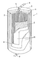
- the electrochemical winding cell 1 consists of a cylindrical housing 2, in particular made of stainless steel.
- the two end faces of this cylindrical housing 2 are each welded to a cover 3, which is filled with a casting compound 4.
- a glass / metal pole feed-through 5 is arranged in the upper cover 3.
- a connecting lug 6 for one pole of the winding cell 1 is passed through this.
- the housing 2 In the lower region of the winding cell 1, the housing 2 has a corresponding connecting lug 7 for the other pole of the winding cell 1.
- a spirally wound electrode package is arranged in the interior of the housing 2. This consists of a lithium anode 8 and a cathode 9, in particular a solid cathode, for example made of MnO2.
- a separator 10 is arranged between anode 8 and cathode 9.
- This separator 10 is formed by a single-layer nonwoven fabric made of polypropylene fibers welded together.
- the fiber diameter is about 8 ⁇ m.
- the nonwoven fabric has a mass per unit area of approx. 40 g ⁇ m ⁇ 2, its thickness is approx. 0.26 mm and the air permeability is approx. 500 dm3 ⁇ s ⁇ 1 ⁇ m2 (at 1 mbar pressure difference).
- the electrochemical winding cell 1 has an electrolyte.
Landscapes
- Chemical & Material Sciences (AREA)
- Chemical Kinetics & Catalysis (AREA)
- Electrochemistry (AREA)
- General Chemical & Material Sciences (AREA)
- Cell Separators (AREA)
Abstract
Description
- Die Erfindung betrifft eine elektrochemische Wickelzelle, insbesondere Lithium-Wickelzelle und dabei insbesondere Li-MnO₂-Wickelzelle, mit einem zwischen den Elektroden (Anode, Kathode) angeordneten Separator aus einem Vliesstoff.
- Ein Problem bei derartigen Hochleistungszellen in Wickelbauweise stellt der Separator dar, welcher üblicherweise aus einem Vliesstoff und/oder einer mikroporösen Folie besteht. So nimmt bei einer Li-MnO₂-Wickelzelle die Dicke der Kathode während der Entladung zu, wobei diese Volumenzunahme teilweise vom Separator aufgefangen werden muß, damit die Zelle sicher entladen werden kann und keine Kurzschlüsse entstehen. Aus diesem Grunde kann in Li-MnO₂-Wickelzellen der Separator nicht beliebig dünn sein.
- Zur Herstellung derartiger Separatoren mit ausreichender Dicke für Li-MnO₂-Wickelzellen ist es bisher üblich, eine Vliesstofflage und eine mikroporöse Folie übereinander zu legen, was jedoch Probleme beim Wickelvorgang mit sich bringt. Auch die Verwendung von Bindemitteln zur Verfestigung der Vliesstoffasern ist nachteilig.
- Ein wesentlicher Nachteil bei relativ dicken Vliesstoffen aus Fasern mit üblichen Durchmessern von größer 20 µm ist jedoch, daß der Innenwiderstand der Wickelzelle derart heraufgesetzt wird, daß hohe Entladeströme nicht mehr möglich sind. Darüber hinaus geht durch einen dicken Vliesstoff Volumen für die aktive Elektrodenmasse verloren, so daß ein Kapazitätsverlust der Wickelzelle die Folge ist.
- Umgekehrt besteht bei relativ geringen Dicken die Gefahr, daß sich das weiche Lithium durch die relativ großen Poren hindurchdrückt, so daß bei derartigen Separatoren für Wickelzellen das Risiko eines inneren Kurzschlusses besteht. Darüber hinaus haben derartige Vliesstoffe den bereits eingangs erwähnten Nachteil, daß nämlich die während der Entladung entstehende Zunahme des Kathodenvolumens nicht vom Separator aufgefangen werden kann.
- Davon ausgehend liegt der Erfindung die Aufgabe zugrunde, einen verbesserten Separator aus einem Vliesstoff für eine elektrochemische Wickelzelle, insbesondere Lithium-Wickelzelle und dabei insbesondere Li-MnO₂-Wickelzelle zu schaffen.
- Als technische Lösung wird mit der Erfindung vorgeschlagen, daß der Separator ein einlagiger Vliesstoff aus miteinander verschweißten Polypropylenfasern mit folgenden technischen Daten ist:
- der Durchmesser der Polypropylenfasern beträgt 5 bis 10 µm
- die Flächenmasse des Vliesstoffes beträgt 20 bis 60 g·m⁻²
- die Dicke des Vliesstoffes beträgt 0,1 bis 0,4 mm, vorzugsweise 0,2 bis 0,3 mm
- die Luftdurchlässigkeit des Vliesstoffes beträgt 400 bis 600 dm³·s⁻¹·m² (bei 1 mbar Druckdifferenz). - Vorzugsweise besitzt der Vliesstoff folgende technische Daten:
- der Faserdurchmesser beträgt ca. 8 µm
- die Flächenmasse des Vliesstoffes beträgt ca. 40 g·m⁻²
- die Dicke des Vliesstoffes beträgt ca. 0,26 mm
- die Luftdurchlässigkeit des Vliesstoffes beträgt ca. 500 dm³·s⁻¹·m² (bei 1 mbar Druckdifferenz). - Schließlich ist der Vliesstoff vorzugsweise kalandriert.
- Bei der Bestimmung der technischen Daten erfolgt die Bestimmung der Flächenmasse nach DIN 53854-75, die Bestimmung der Dicke nach DIN 53855-T01-82 sowie die Bestimmung der Luftdurchlässigkeit nach DIN 53887-77.
- Ein nach dieser technischen Lehre ausgebildeter Separator für eine elektrochemische Wickelzelle, insbesondere Li-MnO₂-Wickelzelle hat den wesentlichen Vorteil, daß durch die Verwendung von dünnen Fasern (Mikrofasern) ein dichter Separator ausreichender Dicke entsteht, der auf optimale Weise die an ihn gerichteten Anforderungen zur Trennung der Elektroden erfüllt. Zunächst kann durch die Verschweißung der Polypropylenfasern miteinander auf die Verwendung eines zusätzlichen Binders verzichtet werden. Die Verfestigung der Fasern kann dabei durch Punktschweißung auf thermische Weise oder mit Ultraschall erfolgen. Die einlagige Ausbildung des Vliesstoffes bringt eine Vereinfachung des Wickelvorganges mit sich. Vor allem ist der Vliesstoff derart mechanisch fest, daß er maschinenverarbeitbar ist. Er ist darüber hinaus auch ausreichend dick für Li-MnO₂-Wickelzellen, so daß das Kathodenwachstum ohne weiteres durch den Separator kompensiert werden kann. Der Separator ist darüber hinaus derart porös, daß der Innenwiderstand der Wickelzelle gering ist, so daß ohne weiteres hohe Entladeströme möglich sind. Schließlich ist der erfindungsgemäße Separator chemisch, thermisch sowie mechanisch derart stabil, daß eine ausreichende Sicherheit gewährleistet ist. Die Gefahr, daß sich das weiche sowie leicht verformbare Lithium durchdrückt und dabei ein Kurzschluß entsteht, existiert bei dem erfindungsgemäßen Separator nicht.
- Ein Ausführungsbeispiel einer erfindungsgemäßen elektrochemischen Wickelzelle wird nachfolgend anhand der Zeichnung beschrieben. Diese zeigt eine perspektivische Ansicht der elektrochemischen Wickelzelle, die zur Sichtbarmachung des Innern sektorartig aufgeschnitten ist, wobei insbesondere die äußeren Lagen erkennbar sind.
- Die elektrochemische Wickelzelle 1 besteht aus einem zylindrischen Gehäuse 2 insbesondere aus Edelstahl. Die beiden Stirnseiten dieses zylindrischen Gehäuses 2 sind jeweils mit einem Deckel 3 verschweißt, der mit einer Vergußmasse 4 jeweils gefüllt ist. Im oberen Deckel 3 ist eine Glas/Metall-Poldurchführung 5 angeordnet. Durch diese ist eine Anschlußfahne 6 für den einen Pol der Wickelzelle 1 hindurchgeführt. Im unteren Bereich der Wickelzelle 1 weist das Gehäuse 2 eine entsprechende Anschlußfahne 7 für den anderen Pol der Wickelzelle 1 auf.
- Im Innern des Gehäuses 2 ist ein spiralförmig aufgewickeltes Elektrodenpaket angeordnet. Dieses besteht aus einer Lithium-Anode 8 sowie aus einer Kathode 9, insbesondere eine Feststoffkathode beispielsweise aus MnO₂. Zwischen Anode 8 und Kathode 9 ist jeweils ein Separator 10 angeordnet.
- Dieser Separator 10 ist durch einen einlagigen Vliesstoff aus miteinander verschweißten Polypropylenfasern gebildet. Der Faserdurchmesser beträgt dabei ca. 8 µm. Der Vliesstoff hat eine Flächenmasse von ca. 40 g·m⁻², seine Dicke beträgt ca. 0,26 mm und die Luftdurchlässigkeit beträgt ca. 500 dm³·s⁻¹·m² (bei 1 mbar Druckdifferenz).
- Schließlich weist die elektrochemische Wickelzelle 1 einen Elektrolyten auf.
-
- 1 elektrochemische Wickelzelle
- 2 Gehäuse
- 3 Deckel
- 4 Vergußmasse
- 5 Poldurchführung
- 6 Anschlußfahne
- 7 Anschlußfahne
- 8 Anode
- 9 Kathode
- 10 Separator
Claims (3)
dadurch gekennzeichnet,
daß der Separator (10) ein einlagiger Vliesstoff aus miteinander verschweißten Polypropylenfasern mit folgenden technischen Daten ist:
- der Durchmesser der Polypropylenfasern beträgt 5 bis 10 µm
- die Flächenmasse des Vliesstoffes beträgt 20 bis 60 g·m⁻²
- die Dicke des Vliesstoffes beträgt 0,1 bis 0,4 mm, vorzugsweise 0,2 bis 0,3 mm
- die Luftdurchlässigkeit des Vliesstoffes betràgt 400 bis 600 dm³·s⁻¹·m² (bei 1 mbar Druckdifferenz).
- der Faserdurchmesser beträgt ca. 8 µm
- die Flächenmasse des Vliesstoffes beträgt ca. 40 g·m⁻²
- die Dichte des Vliesstoffes beträgt ca. 0,26 mm
- die Luftdurchlässigkeit des Vliesstoffes beträgt ca. 500 dm³·s⁻¹·m² ( bei 1 mbar Druckdifferenz).
Applications Claiming Priority (2)
| Application Number | Priority Date | Filing Date | Title |
|---|---|---|---|
| DE3935462 | 1989-10-25 | ||
| DE3935462A DE3935462A1 (de) | 1989-10-25 | 1989-10-25 | Elektrochemische wickelzelle |
Publications (2)
| Publication Number | Publication Date |
|---|---|
| EP0424627A2 true EP0424627A2 (de) | 1991-05-02 |
| EP0424627A3 EP0424627A3 (en) | 1991-10-09 |
Family
ID=6392134
Family Applications (1)
| Application Number | Title | Priority Date | Filing Date |
|---|---|---|---|
| EP19900115947 Withdrawn EP0424627A3 (en) | 1989-10-25 | 1990-08-21 | Cell of wounded configuration |
Country Status (2)
| Country | Link |
|---|---|
| EP (1) | EP0424627A3 (de) |
| DE (1) | DE3935462A1 (de) |
Cited By (3)
| Publication number | Priority date | Publication date | Assignee | Title |
|---|---|---|---|---|
| FR2715252A1 (fr) * | 1994-01-18 | 1995-07-21 | Pall Corp | Séparateur de batterie. |
| DE19804649A1 (de) * | 1998-02-06 | 1999-08-12 | Hoppecke Batterie Systeme Gmbh | Elektrodenanordnung für Nickel-Cadmium-Akkumulatoren und Verfahren zu ihrer Herstellung |
| US6458484B2 (en) | 1998-02-06 | 2002-10-01 | Hoppecke Batterie Systeme Gmbh | Fiber-structure electrode system for nickel-cadmium batteries and procedure for its manufacture |
Family Cites Families (1)
| Publication number | Priority date | Publication date | Assignee | Title |
|---|---|---|---|---|
| JPS5991662A (ja) * | 1982-11-17 | 1984-05-26 | Japan Vilene Co Ltd | 電池用セパレ−タ及びその製造方法 |
-
1989
- 1989-10-25 DE DE3935462A patent/DE3935462A1/de not_active Withdrawn
-
1990
- 1990-08-21 EP EP19900115947 patent/EP0424627A3/de not_active Withdrawn
Cited By (3)
| Publication number | Priority date | Publication date | Assignee | Title |
|---|---|---|---|---|
| FR2715252A1 (fr) * | 1994-01-18 | 1995-07-21 | Pall Corp | Séparateur de batterie. |
| DE19804649A1 (de) * | 1998-02-06 | 1999-08-12 | Hoppecke Batterie Systeme Gmbh | Elektrodenanordnung für Nickel-Cadmium-Akkumulatoren und Verfahren zu ihrer Herstellung |
| US6458484B2 (en) | 1998-02-06 | 2002-10-01 | Hoppecke Batterie Systeme Gmbh | Fiber-structure electrode system for nickel-cadmium batteries and procedure for its manufacture |
Also Published As
| Publication number | Publication date |
|---|---|
| DE3935462A1 (de) | 1991-05-02 |
| EP0424627A3 (en) | 1991-10-09 |
Similar Documents
| Publication | Publication Date | Title |
|---|---|---|
| DE2832513C3 (de) | ||
| DE2822396C2 (de) | Separator für einen Bleiakkumulator | |
| DE69022503T2 (de) | Gewickelte Elektrodenanordnung für eine elektrochemische Zelle. | |
| EP2186149B1 (de) | Vliesstoff mit partikelfüllung | |
| EP1198854B1 (de) | Elektrodeneinheit für wiederaufladbare elektrochemische zellen | |
| DE3780090T2 (de) | Elektrochemische zelle. | |
| DE2554402C3 (de) | Primärelement | |
| EP0416244B1 (de) | Gasdicht verschlossene alkalische Sekundärzelle | |
| DE69413301T2 (de) | Verfahren zur Herstellung einer sekundären alkalischen Batterie | |
| CH694715A5 (de) | Lithium-Flachzelle. | |
| DE69204502T2 (de) | Glasversiegelungswerkstoffe für Natrium-Schwefel-Batterien und damit hergestellte Batterien. | |
| DE19645836B4 (de) | Zelle mit spiralförmig gewickelten Elektroden | |
| DE202021100473U1 (de) | Elektrochemische Zelle mit Kontaktfahne | |
| DE3852795T2 (de) | Elektrochemische Zelle. | |
| DE2835503A1 (de) | Nickeloxid/wasserstoffzellen mit in den diffusionskoerper integrierten negativen elektroden | |
| EP0424627A2 (de) | Elektrochemische Wickelzelle | |
| DE69122747T2 (de) | Separator für alkali-zink-batterien | |
| DE1094829B (de) | Scheider fuer Akkumulatoren, insbesondere fuer Silber-Zink-Akkumulatoren | |
| DE69105184T2 (de) | Separator für alkalische Akkumulatoren. | |
| EP0218028B1 (de) | Gasdicht verschlossener Nickel/Cadmium-Akkumulator | |
| DE3532697C2 (de) | ||
| DE3139352C2 (de) | ||
| DE19931348C1 (de) | Verfahren zur Oberflächenbehandlung eines faserförmigen Polyphenylsulfids oder Polysulfons | |
| DE8912617U1 (de) | Elektrochemische Zelle | |
| DE10037711B4 (de) | Gewickelte Batterieelektrode mit einer rechteckigen porösen Basisplatte |
Legal Events
| Date | Code | Title | Description |
|---|---|---|---|
| PUAI | Public reference made under article 153(3) epc to a published international application that has entered the european phase |
Free format text: ORIGINAL CODE: 0009012 |
|
| AK | Designated contracting states |
Kind code of ref document: A2 Designated state(s): DE FR GB |
|
| PUAL | Search report despatched |
Free format text: ORIGINAL CODE: 0009013 |
|
| AK | Designated contracting states |
Kind code of ref document: A3 Designated state(s): DE FR GB |
|
| 17P | Request for examination filed |
Effective date: 19920324 |
|
| 17Q | First examination report despatched |
Effective date: 19930212 |
|
| STAA | Information on the status of an ep patent application or granted ep patent |
Free format text: STATUS: THE APPLICATION IS DEEMED TO BE WITHDRAWN |
|
| 18D | Application deemed to be withdrawn |
Effective date: 19930623 |