EP0424402B1 - Verfahren in einem impulsbeschleuniger zur beschleunigung eines magnetischen rotierenden plasmas - Google Patents
Verfahren in einem impulsbeschleuniger zur beschleunigung eines magnetischen rotierenden plasmas Download PDFInfo
- Publication number
- EP0424402B1 EP0424402B1 EP89905802A EP89905802A EP0424402B1 EP 0424402 B1 EP0424402 B1 EP 0424402B1 EP 89905802 A EP89905802 A EP 89905802A EP 89905802 A EP89905802 A EP 89905802A EP 0424402 B1 EP0424402 B1 EP 0424402B1
- Authority
- EP
- European Patent Office
- Prior art keywords
- axis
- plasma
- electrodes
- accelerator
- magnetic
- Prior art date
- Legal status (The legal status is an assumption and is not a legal conclusion. Google has not performed a legal analysis and makes no representation as to the accuracy of the status listed.)
- Expired - Lifetime
Links
- 238000000034 method Methods 0.000 title claims abstract description 12
- 230000007935 neutral effect Effects 0.000 claims abstract description 9
- 230000007704 transition Effects 0.000 claims abstract description 6
- 230000001133 acceleration Effects 0.000 claims description 12
- 230000005684 electric field Effects 0.000 claims description 9
- 239000002245 particle Substances 0.000 description 10
- 239000007789 gas Substances 0.000 description 6
- 150000002500 ions Chemical class 0.000 description 5
- 230000006835 compression Effects 0.000 description 4
- 238000007906 compression Methods 0.000 description 4
- 238000010586 diagram Methods 0.000 description 4
- 238000010438 heat treatment Methods 0.000 description 4
- 238000005036 potential barrier Methods 0.000 description 3
- IJGRMHOSHXDMSA-UHFFFAOYSA-N Atomic nitrogen Chemical compound N#N IJGRMHOSHXDMSA-UHFFFAOYSA-N 0.000 description 2
- 230000004888 barrier function Effects 0.000 description 2
- 230000000694 effects Effects 0.000 description 2
- 230000003993 interaction Effects 0.000 description 2
- 239000013598 vector Substances 0.000 description 2
- 230000008901 benefit Effects 0.000 description 1
- 238000004364 calculation method Methods 0.000 description 1
- 230000005495 cold plasma Effects 0.000 description 1
- 230000007423 decrease Effects 0.000 description 1
- 238000002474 experimental method Methods 0.000 description 1
- 230000004992 fission Effects 0.000 description 1
- 230000004907 flux Effects 0.000 description 1
- 230000004927 fusion Effects 0.000 description 1
- 238000002347 injection Methods 0.000 description 1
- 239000007924 injection Substances 0.000 description 1
- 238000005468 ion implantation Methods 0.000 description 1
- 239000007788 liquid Substances 0.000 description 1
- 239000000463 material Substances 0.000 description 1
- 230000004048 modification Effects 0.000 description 1
- 238000012986 modification Methods 0.000 description 1
- 229910052757 nitrogen Inorganic materials 0.000 description 1
- 230000035515 penetration Effects 0.000 description 1
- 230000008569 process Effects 0.000 description 1
- 238000005086 pumping Methods 0.000 description 1
- 230000009291 secondary effect Effects 0.000 description 1
- 238000000926 separation method Methods 0.000 description 1
Images


Classifications
-
- H—ELECTRICITY
- H05—ELECTRIC TECHNIQUES NOT OTHERWISE PROVIDED FOR
- H05H—PLASMA TECHNIQUE; PRODUCTION OF ACCELERATED ELECTRICALLY-CHARGED PARTICLES OR OF NEUTRONS; PRODUCTION OR ACCELERATION OF NEUTRAL MOLECULAR OR ATOMIC BEAMS
- H05H1/00—Generating plasma; Handling plasma
- H05H1/24—Generating plasma
- H05H1/52—Generating plasma using exploding wires or spark gaps
Definitions
- This invention relates to a method in a pulsed accelerator for accelerating a magnetized rotating plasma.
- This type of accelerator represents a new class of super-powerful plasma accelerators which can be called centrifugal plasma accelerators or accelerators with magnetized plasma.
- the purpose of the present invention is to reach a speed of the plasma in a pulsed accelerator, which speed is higher than the Alfvén limit, by using the forces which arise because of rotation of the plasma, for the acceleration along the axis of the accelerator, and thus to generate a plasma at a substantially increased energy level, which is useful in applications such as plasma physics, mass and charge separation, fusion by beams and direct fission in unstable nuclei bombarded by beams, space research, and modification of surface properties of different materials by ion implantation.
- the pulsed accelerator in which the method of the invention is applied comprises a magnetic system arranged symmetrically around an axis, two coxial electrodes extending symmetrically along said axis inside the magnetic system, said electrodes being spaced from each other in the transverse direction of said axis to form a vacuum chamber, two pulsed power sources connected to the magnetic system and the electrodes, respectively, and openings in the inner electrode in a cross section perpendicular to said axis for the supply of a neutral gas to the space defined by said electrodes, and for said purpose the method of the invention has obtained the characteristics appearing from claim 1.
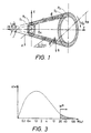
- FIG 1 In order to explain the acceleration of a rotating plasma in a gradient magnetic field reference is made to FIG 1 wherein there is shown an axisymmetric magnetic layer in which a rotating plasma is located, said layer being limited by cross sections A-A and B-B, respectively, at the ends thereof along the axis z.
- the drift current j ⁇ is a consequence of secondary effect due to difference in the drift velocities of electrons and ions.
- the forces due to gradients of plasma density, temperature or Larmor rotational velocity can be neglected.
- V dri V dre E/B .
- the projection of the forces, which are taken into account, on the direction of the magnetic field are equal to each other, e.g. wherein the index t notifies projection of forces on the magnetic field lines.
- FIG 3 shows the Bolzman-Maxellian distribution of indicated along the vertical axis, W being the energy of particles and T being the plasma temperature.
- the shadowed energy tail in FIG 3 shows the number of particles which can escape from cross section A-A.
- the relative proportion of particles which escape from the potential barrier is less than In other words, the motion of rotating plasma in a conical magnetic layer has two main features:
- the pulsed accelerator of FIG 4 is a single step accelerator providing a rotating plasma according to the principles described with reference to FIGS 1 - 3.
- This accelerator comprises two coaxial electrodes, an outer electrode 10 and an inner electrode 11 which extend symmetrically along a common axis spaced from each other to form a dielectric vacuum chamber which includes from the left to the right a circular cylindrical portion 12, a conical transition portion 13 flaring from portion 12, and a circular cylindrical portion 14 having a larger diameter than portion 12. Said latter portion also has a greater length than portion 12 and is termed collector.
- the outer electrode extends beyond the inner electrode which converges to a pointed tip so that the outlet opening of the accelerator at the left end thereof includes the full area defined by the outer electrode.
- the electrodes are surrounded by a magnetic system including a coil 15 or a number of such coils arranged symmetrically around the axis of the electrodes and following the shape thereof.
- the dielectric vacuum chamber formed between the electrodes is connected to a differential pumping system 16 having vacuum pumps 17.
- a set of openings 18 are provided in the inner electrode 11 in the transition portion thereof, which are connected to an injector 19 for neutral gas.
- the coil or coils are connected to a pulsed power source (not shown).
- Cathode rings 20 are provided in the outer electrode for E x B discharge and are connected to one terminal of a pulsed discharge power source 21, the other terminal being connected to the inner electrode forming the anode.
- the magnetic coil system 15 creates a pulsed axisymmetric magnetic field which is high enough to satisfy condition (b) above.
- the risetime and the pulselength are long enough to impose a distributed induced current in the anode body to stop practically all field penetration.
- the vacuum chamber has to satisfy three main requirements:
- the pulsed magnetic flux is concentrated between the vacuum chamber and the inner electrode 11.
- the inner electrode can be cooled by liquid nitrogen or be provided with built in magnetic coils.
- the current ratio between inner and outer magnetic currents can be chosen to place the separatrix on the inner electrode surface.
- Neutral gas which is injected in the accelerating layer from injector 19 through openings 18 is either ionized by E x B discharge and accelerated to the collector 14 or pumped out as neutral gas by the pumps 17.
- the plasma leaving the accelerating region 13 moves into the collector 14, which is a cylindrical magnetic layer.
- the length of the collector must be long enough to allow the whole plasma body to move into this region and also to allow the electrical field to be switched off and to stop the plasma rotation in the collector. This means that the mirror effect due to rotation in the accelerator output can be avoided.
- the voltage between the electrodes can be increased, which leads to a higher acceleration of the last parts of the plasma body.
- the density of the plasma in the outlet of the accelerator can be compressed. This also means a way of increasing the ⁇ -value.
- the magnetic system 15 of the accelerator has to be made longer than the inner electrode (see FIG 4).
- an ultra-powerful accelerator By building an accelerator as described with reference to FIG 4 and comprising a certain number of steps an ultra-powerful accelerator can be provided the selected energy layer being used in combination with the compressing effect of the forming electrical fields in the different steps.
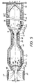
- FIG 5 A diagrammatic axial cross sectional view of a two step accelerator is shown in FIG 5. With reference to the diagram in FIG 6 it is assumed that the neutral gas injector starts at time t1 and is open until time t2. The voltage between the electrodes 10 and 11 is applied at time t2 and shortcircuited at time t3. The voltage puls length must be long enough to allow ionization and acceleration.
- the plasma position I in FIG 5 is shown at time t3.
- the plasma length is 1.
- the rotation of the plasma is stopped due to shortcircuiting of the driving voltage, but the plasma will move along the guiding fieldlines due to inertia.
- the growing puls form of the voltage as shown in FIG 6 is necessary in order to compress the plasma in a several step accelerator.
- the plasma length at time t3 is 1 and the total length from the beginning of collector up to the second cathode ring 20 is L, for the same time the first and the last particle of the plasma body must pass over different distances L-1 and L. In other words, their speed at the time t3 must be equal to and and makes the ratio of voltage at the beginning and the end of the puls equal to
- the second accelerator unit must have a greater length due to the speed which has been achieved in the preceding accelerator units. After the last accelerator step the compression of the plasma body has to be at the end of the plasma accelerator in order to reach the highest ⁇ -values.
- the radii ⁇ 1 and ⁇ 2, FIG 5, must be big enough for the current density induced in the plasma during the motion in the transition part of the field to be smaller than current density in the coils of guiding field.
- ⁇ 1,2 is the speed of plasma motion along the field in sections 1 and 2
- n is the plasma density
- jB is the current density in the coils
- ⁇ 1 and ⁇ 2 are the radii of transition parts.
- the plasma heating depends also on the gradient of rotational speed along the radius and compression along the axis.
- plasma heating is a negative phenomena in an accelerator, because it prevents plasma compression and thus complicates the second step acceleration and also decreases the rotational speed compared with what could be reached in a cold plasma.
Landscapes
- Physics & Mathematics (AREA)
- Engineering & Computer Science (AREA)
- Plasma & Fusion (AREA)
- Spectroscopy & Molecular Physics (AREA)
- Plasma Technology (AREA)
- Particle Accelerators (AREA)
Claims (5)
- Verfahren bei einem Impulsbeschleuniger zum Beschleunigen eines magnetisierten rotierenden Plasmas, wobei der Beschleuniger ein symmetrisch um eine Achse angeordnetes Magnetsystem (15), zwei sich innerhalb des Magnetsystems symmetrisch längs der Achse erstreckende koaxiale Elektroden (10, 11), die unter Bildung einer Vakuumkammer in der Querrichtung der Achse voneinander beabstandet sind, zwei an das Magnetsystem bzw. die Elektroden angeschlossene gepulste Stromversorgungen und in der inneren Elektrode in einem Querschnitt senkrecht zur Achse vorgesehene Öffnungen für die Zuspeisung eines neutralen Gases zu dem durch die Elektroden festgelegten Raum umfaßt,
dadurch gekennzeichnet, daß das Magnetfeld eingeschlossen ist zur Bildung einer Schicht, bestehend aus einem ersten zylindrischen Abschnitt mit einem kleineren Innendurchmesser und einem zweiten zylindrischen Abschnitt mit einem größeren Durchmesser sowie einem die ersten und zweiten zylindrischen Abschnitte verbindenden Übergangsabschnitt, die Abschnitte achssymmetrisch um die gemeinsame Achse herum angeordnet sind, (und) das Magnetfeld während der Ionisierungs- und Beschleunigungsperiode senkrecht zum elektrischen Feld in der Vakuumkammer liegt. - Verfahren nach Anspruch 1,
dadurch gekennzeichnet, daß der Übergangsabschnitt als eine konische Schicht geformt ist oder wird. - Verfahren nach Anspruch 1,
dadurch gekennzeichnet, daß das elektrische Feld senkrecht zum Magnetfeld angelegt wird. - Verfahren nach Anspruch 1,
dadurch gekennzeichnet, daß die Stärke des elektrischen Felds zeitabhängig so geregelt wird, daß sie in jedem Impuls eine zunehmende Größe aufweist. - Verfahren nach Anspruch 1,
dadurch gekennzeichnet, daß das Magnetfeld im Raum längs der Achse wiederholt (erzeugt) wird.
Priority Applications (1)
| Application Number | Priority Date | Filing Date | Title |
|---|---|---|---|
| AT89905802T ATE104496T1 (de) | 1988-05-05 | 1989-05-02 | Verfahren in einem impulsbeschleuniger zur beschleunigung eines magnetischen rotierenden plasmas. |
Applications Claiming Priority (3)
| Application Number | Priority Date | Filing Date | Title |
|---|---|---|---|
| SE8801705 | 1988-05-05 | ||
| SE8801705A SE459378B (sv) | 1988-05-05 | 1988-05-05 | Saett i en pulsad accelerator foer accelerering av magnetiserat roterande plasma |
| PCT/SE1989/000247 WO1989011207A1 (en) | 1988-05-05 | 1989-05-02 | Method in a pulsed accelerator for accelerating a magnetized rotating plasma |
Publications (2)
| Publication Number | Publication Date |
|---|---|
| EP0424402A1 EP0424402A1 (de) | 1991-05-02 |
| EP0424402B1 true EP0424402B1 (de) | 1994-04-13 |
Family
ID=20372246
Family Applications (1)
| Application Number | Title | Priority Date | Filing Date |
|---|---|---|---|
| EP89905802A Expired - Lifetime EP0424402B1 (de) | 1988-05-05 | 1989-05-02 | Verfahren in einem impulsbeschleuniger zur beschleunigung eines magnetischen rotierenden plasmas |
Country Status (7)
| Country | Link |
|---|---|
| US (1) | US5300861A (de) |
| EP (1) | EP0424402B1 (de) |
| JP (1) | JP2863237B2 (de) |
| AU (1) | AU3567789A (de) |
| DE (1) | DE68914669T2 (de) |
| SE (1) | SE459378B (de) |
| WO (1) | WO1989011207A1 (de) |
Families Citing this family (10)
| Publication number | Priority date | Publication date | Assignee | Title |
|---|---|---|---|---|
| DE19948229C1 (de) * | 1999-10-07 | 2001-05-03 | Daimler Chrysler Ag | Hochfrequenz-Ionenquelle |
| AT502984B8 (de) * | 2003-09-15 | 2008-10-15 | Qasar Technologieentwicklung Gmbh | Verfahren und einrichtung zur erzeugung von alfven-wellen |
| RU2253953C1 (ru) * | 2003-09-22 | 2005-06-10 | Государственное научное учреждение "Государственный научно-исследовательский институт прикладной механики и электродинамики Московского авиационного института (государственного технического университета)" (ГНУ НИИ ПМЭ МАИ) | Импульсный плазменный ускоритель и способ ускорения плазмы |
| US7870720B2 (en) * | 2006-11-29 | 2011-01-18 | Lockheed Martin Corporation | Inlet electromagnetic flow control |
| WO2008105736A2 (en) | 2007-03-01 | 2008-09-04 | Plasmatrix Materials Ab | Method, material and apparatus for enhancing dynamic stiffness |
| WO2011103194A2 (en) * | 2010-02-16 | 2011-08-25 | University Of Florida Research Foundation, Inc. | Method and apparatus for small satellite propulsion |
| RU2634849C2 (ru) * | 2012-08-29 | 2017-11-07 | Дженерал Фьюжн Инк. | Устройство для ускорения и сжатия плазмы |
| WO2014131055A1 (en) | 2013-02-25 | 2014-08-28 | University Of Florida Research Foundation, Incorporated | Method and apparatus for providing high control authority atmospheric plasma |
| WO2014210519A2 (en) * | 2013-06-27 | 2014-12-31 | Nonlinear Ion Dynamics, Llc. | Methods, devices and systems for fusion reactions |
| CN103731967A (zh) * | 2014-01-21 | 2014-04-16 | 中国科学院电工研究所 | 一种等离子体背场增强轨道 |
Family Cites Families (7)
| Publication number | Priority date | Publication date | Assignee | Title |
|---|---|---|---|---|
| US2992345A (en) * | 1958-03-21 | 1961-07-11 | Litton Systems Inc | Plasma accelerators |
| US3441798A (en) * | 1962-09-19 | 1969-04-29 | Didier Veron | Plasma gun utilizing successive arcs for generating and accelerating the plasma |
| DE1200447B (de) * | 1964-03-05 | 1965-09-09 | Siemens Ag | Vorrichtung zur Erzeugung eines Plasmastrahles |
| US3585441A (en) * | 1968-12-05 | 1971-06-15 | Gen Electric | Shock ionization gas accelerator |
| SU307742A1 (ru) * | 1969-07-28 | 1982-11-23 | Komelkov V S | Плазменный инжектор |
| SU600941A1 (ru) * | 1976-11-10 | 1980-05-25 | Государственный Научно-Исследовательский Энергетический Институт Им.Г.М.Кржижановского | Плазменный ускоритель |
| SU1140641A1 (ru) * | 1983-06-24 | 1986-11-30 | Объединенный Институт Ядерных Исследований | Плазменный источник электронов |
-
1988
- 1988-05-05 SE SE8801705A patent/SE459378B/sv not_active IP Right Cessation
-
1989
- 1989-05-02 DE DE68914669T patent/DE68914669T2/de not_active Expired - Fee Related
- 1989-05-02 AU AU35677/89A patent/AU3567789A/en not_active Abandoned
- 1989-05-02 EP EP89905802A patent/EP0424402B1/de not_active Expired - Lifetime
- 1989-05-02 WO PCT/SE1989/000247 patent/WO1989011207A1/en not_active Ceased
- 1989-05-02 JP JP1505730A patent/JP2863237B2/ja not_active Expired - Lifetime
-
1993
- 1993-03-16 US US08/032,721 patent/US5300861A/en not_active Expired - Fee Related
Also Published As
| Publication number | Publication date |
|---|---|
| EP0424402A1 (de) | 1991-05-02 |
| DE68914669T2 (de) | 1994-11-24 |
| JP2863237B2 (ja) | 1999-03-03 |
| WO1989011207A1 (en) | 1989-11-16 |
| SE8801705D0 (sv) | 1988-05-05 |
| SE459378B (sv) | 1989-06-26 |
| AU3567789A (en) | 1989-11-29 |
| DE68914669D1 (de) | 1994-05-19 |
| JPH03505944A (ja) | 1991-12-19 |
| US5300861A (en) | 1994-04-05 |
Similar Documents
| Publication | Publication Date | Title |
|---|---|---|
| US7294969B2 (en) | Two-stage hall effect plasma accelerator including plasma source driven by high-frequency discharge | |
| RU2344577C2 (ru) | Плазменный ускоритель с закрытым дрейфом электронов | |
| US4293794A (en) | Generation of intense, high-energy ion pulses by magnetic compression of ion rings | |
| RU2030134C1 (ru) | Плазменный ускоритель с замкнутым дрейфом электронов | |
| US6215124B1 (en) | Multistage ion accelerators with closed electron drift | |
| US3418206A (en) | Particle accelerator | |
| Geller | Electron cyclotron resonance sources: Historical review and future prospects | |
| EP1082540B1 (de) | Magnetfeldgestaltung in ionenbeschleunigern mit geschlossener elektronenlaufbahn | |
| KR102523488B1 (ko) | 자화 플라즈마 생성 및 가속을 위한 시스템 및 방법 | |
| US5300861A (en) | Method in a pulsed accelerator for accelerating a magnetized rotating plasma | |
| US3634704A (en) | Apparatus for the production of highly stripped ions | |
| JPS61118938A (ja) | 超高周波イオン源点弧方法および装置 | |
| Geller et al. | The multiply charged ion source Minimafios | |
| WO1992021221A1 (en) | System and method for increasing the efficiency of a cyclotron | |
| US7009342B2 (en) | Plasma electron-emitting source | |
| CA1257319A (en) | Energy conversion system | |
| Xie et al. | Production of high charge state ions with the Advanced Electron Cyclotron Resonance Ion Source at LBNL | |
| Hamilton et al. | Physics and applications of charged particle beam sources | |
| RU2156555C1 (ru) | Способ получения и ускорения плазмы и ускоритель плазмы с замкнутым дрейфом электронов для его осуществления | |
| RU2050044C1 (ru) | Способ ускорения электронов в цилиндрическом бетатроне и устройство для его осуществления | |
| Shope et al. | Laser-based foilless diode | |
| RU2071137C1 (ru) | Источник ионов | |
| US8138677B2 (en) | Radial hall effect ion injector with a split solenoid field | |
| US3032490A (en) | Destruction of neutral particles in a device for producing a high density plasma | |
| JPH089780B2 (ja) | 薄膜形成装置 |
Legal Events
| Date | Code | Title | Description |
|---|---|---|---|
| PUAI | Public reference made under article 153(3) epc to a published international application that has entered the european phase |
Free format text: ORIGINAL CODE: 0009012 |
|
| 17P | Request for examination filed |
Effective date: 19901101 |
|
| AK | Designated contracting states |
Kind code of ref document: A1 Designated state(s): AT BE CH DE FR GB IT LI LU NL SE |
|
| 17Q | First examination report despatched |
Effective date: 19930405 |
|
| GRAA | (expected) grant |
Free format text: ORIGINAL CODE: 0009210 |
|
| AK | Designated contracting states |
Kind code of ref document: B1 Designated state(s): AT BE CH DE FR GB IT LI LU NL SE |
|
| PG25 | Lapsed in a contracting state [announced via postgrant information from national office to epo] |
Ref country code: SE Free format text: THE PATENT HAS BEEN ANNULLED BY A DECISION OF A NATIONAL AUTHORITY Effective date: 19940413 |
|
| REF | Corresponds to: |
Ref document number: 104496 Country of ref document: AT Date of ref document: 19940415 Kind code of ref document: T |
|
| REF | Corresponds to: |
Ref document number: 68914669 Country of ref document: DE Date of ref document: 19940519 |
|
| PGFP | Annual fee paid to national office [announced via postgrant information from national office to epo] |
Ref country code: NL Payment date: 19940531 Year of fee payment: 6 |
|
| PGFP | Annual fee paid to national office [announced via postgrant information from national office to epo] |
Ref country code: CH Payment date: 19940628 Year of fee payment: 6 |
|
| ITF | It: translation for a ep patent filed | ||
| PGFP | Annual fee paid to national office [announced via postgrant information from national office to epo] |
Ref country code: LU Payment date: 19940731 Year of fee payment: 6 |
|
| PGFP | Annual fee paid to national office [announced via postgrant information from national office to epo] |
Ref country code: BE Payment date: 19940823 Year of fee payment: 6 Ref country code: AT Payment date: 19940823 Year of fee payment: 6 |
|
| ET | Fr: translation filed | ||
| EPTA | Lu: last paid annual fee | ||
| PLBE | No opposition filed within time limit |
Free format text: ORIGINAL CODE: 0009261 |
|
| STAA | Information on the status of an ep patent application or granted ep patent |
Free format text: STATUS: NO OPPOSITION FILED WITHIN TIME LIMIT |
|
| 26N | No opposition filed | ||
| PG25 | Lapsed in a contracting state [announced via postgrant information from national office to epo] |
Ref country code: LU Free format text: LAPSE BECAUSE OF NON-PAYMENT OF DUE FEES Effective date: 19950502 Ref country code: AT Effective date: 19950502 |
|
| PG25 | Lapsed in a contracting state [announced via postgrant information from national office to epo] |
Ref country code: LI Effective date: 19950531 Ref country code: CH Effective date: 19950531 Ref country code: BE Effective date: 19950531 |
|
| BERE | Be: lapsed |
Owner name: BERGSTROM JAN Effective date: 19950531 Owner name: SILLESEN ALFRED Effective date: 19950531 Owner name: HELGESEN HERMAN Effective date: 19950531 Owner name: KOUZNETSOV VLADIMIR Effective date: 19950531 |
|
| PGFP | Annual fee paid to national office [announced via postgrant information from national office to epo] |
Ref country code: FR Payment date: 19951130 Year of fee payment: 7 Ref country code: DE Payment date: 19951130 Year of fee payment: 7 |
|
| PG25 | Lapsed in a contracting state [announced via postgrant information from national office to epo] |
Ref country code: NL Effective date: 19951201 |
|
| REG | Reference to a national code |
Ref country code: CH Ref legal event code: PL |
|
| NLV4 | Nl: lapsed or anulled due to non-payment of the annual fee |
Effective date: 19951201 |
|
| PG25 | Lapsed in a contracting state [announced via postgrant information from national office to epo] |
Ref country code: FR Effective date: 19970131 |
|
| PG25 | Lapsed in a contracting state [announced via postgrant information from national office to epo] |
Ref country code: DE Effective date: 19970201 |
|
| REG | Reference to a national code |
Ref country code: FR Ref legal event code: ST |
|
| PGFP | Annual fee paid to national office [announced via postgrant information from national office to epo] |
Ref country code: GB Payment date: 19981027 Year of fee payment: 10 |
|
| PG25 | Lapsed in a contracting state [announced via postgrant information from national office to epo] |
Ref country code: GB Free format text: LAPSE BECAUSE OF NON-PAYMENT OF DUE FEES Effective date: 19990502 |
|
| GBPC | Gb: european patent ceased through non-payment of renewal fee |
Effective date: 19990502 |
|
| PG25 | Lapsed in a contracting state [announced via postgrant information from national office to epo] |
Ref country code: IT Free format text: LAPSE BECAUSE OF NON-PAYMENT OF DUE FEES Effective date: 20050502 |