EP0424229B1 - Machine and method using the machine for cleaning a surface - Google Patents
Machine and method using the machine for cleaning a surface Download PDFInfo
- Publication number
- EP0424229B1 EP0424229B1 EP90402868A EP90402868A EP0424229B1 EP 0424229 B1 EP0424229 B1 EP 0424229B1 EP 90402868 A EP90402868 A EP 90402868A EP 90402868 A EP90402868 A EP 90402868A EP 0424229 B1 EP0424229 B1 EP 0424229B1
- Authority
- EP
- European Patent Office
- Prior art keywords
- machine
- lateral
- respect
- device carrier
- machine body
- Prior art date
- Legal status (The legal status is an assumption and is not a legal conclusion. Google has not performed a legal analysis and makes no representation as to the accuracy of the status listed.)
- Expired - Lifetime
Links
Images


Classifications
-
- A—HUMAN NECESSITIES
- A47—FURNITURE; DOMESTIC ARTICLES OR APPLIANCES; COFFEE MILLS; SPICE MILLS; SUCTION CLEANERS IN GENERAL
- A47L—DOMESTIC WASHING OR CLEANING; SUCTION CLEANERS IN GENERAL
- A47L11/00—Machines for cleaning floors, carpets, furniture, walls, or wall coverings
- A47L11/40—Parts or details of machines not provided for in groups A47L11/02 - A47L11/38, or not restricted to one of these groups, e.g. handles, arrangements of switches, skirts, buffers, levers
- A47L11/4036—Parts or details of the surface treating tools
-
- A—HUMAN NECESSITIES
- A47—FURNITURE; DOMESTIC ARTICLES OR APPLIANCES; COFFEE MILLS; SPICE MILLS; SUCTION CLEANERS IN GENERAL
- A47L—DOMESTIC WASHING OR CLEANING; SUCTION CLEANERS IN GENERAL
- A47L11/00—Machines for cleaning floors, carpets, furniture, walls, or wall coverings
- A47L11/40—Parts or details of machines not provided for in groups A47L11/02 - A47L11/38, or not restricted to one of these groups, e.g. handles, arrangements of switches, skirts, buffers, levers
- A47L11/4061—Steering means; Means for avoiding obstacles; Details related to the place where the driver is accommodated
-
- B—PERFORMING OPERATIONS; TRANSPORTING
- B60—VEHICLES IN GENERAL
- B60S—SERVICING, CLEANING, REPAIRING, SUPPORTING, LIFTING, OR MANOEUVRING OF VEHICLES, NOT OTHERWISE PROVIDED FOR
- B60S3/00—Vehicle cleaning apparatus not integral with vehicles
- B60S3/008—Vehicle cleaning apparatus not integral with vehicles for interiors of land vehicles
-
- E—FIXED CONSTRUCTIONS
- E01—CONSTRUCTION OF ROADS, RAILWAYS, OR BRIDGES
- E01H—STREET CLEANING; CLEANING OF PERMANENT WAYS; CLEANING BEACHES; DISPERSING OR PREVENTING FOG IN GENERAL CLEANING STREET OR RAILWAY FURNITURE OR TUNNEL WALLS
- E01H1/00—Removing undesirable matter from roads or like surfaces, with or without moistening of the surface
- E01H1/02—Brushing apparatus, e.g. with auxiliary instruments for mechanically loosening dirt
- E01H1/05—Brushing apparatus, e.g. with auxiliary instruments for mechanically loosening dirt with driven brushes
-
- A—HUMAN NECESSITIES
- A47—FURNITURE; DOMESTIC ARTICLES OR APPLIANCES; COFFEE MILLS; SPICE MILLS; SUCTION CLEANERS IN GENERAL
- A47L—DOMESTIC WASHING OR CLEANING; SUCTION CLEANERS IN GENERAL
- A47L2201/00—Robotic cleaning machines, i.e. with automatic control of the travelling movement or the cleaning operation
- A47L2201/04—Automatic control of the travelling movement; Automatic obstacle detection
Definitions
- EP-A-0.087.936 and FR-A-2.297.286 describe a machine the means of which for moving a cleaning tool holder relative to the body of the machine not only make it possible to bring the tool to a prefixed position , according to an order given by the operator of the machine, but also to ensure a passive adjustment of the working width of the machine as a function of obstacles, thanks to a certain hydraulic or pneumatic "elasticity".
- EP-A-0.087.936 further describes means of elastic connection between a brush (the lateral tool) and a brush holder, designed to maintain the brush at the appropriate sweep angle; as well as means of reflex reaction to an obstacle, comprising in particular a sensitive bar.
- the invention aims to make it easier to pilot these machines.
- a device for cleaning a surface presenting obstacles comprising a body provided on at least one side with a lateral tool and, for each lateral tool, means for moving relative to the body a tool holder, as well as elastic connection means between the tool holder and the lateral tool, to make the lateral tool resiliently movable relative to the tool holder; characterized in that said means for moving relative to the body a tool holder as well as said elastic connection means between the tool holder and the lateral tool, are both part of means for automatically adjusting the working width of the depending on the obstacles possibly surrounding it, so that it can be moved over said surface along a trajectory comprising a minimum of changes in direction, said means of elastic connection between the tool holder and the lateral tool providing a level passive automatic adjustment of the working width, said means for moving relative to the body a tool holder providing an active level of adjustment automatic working width.
- the machine according to the invention can move along a trajectory comprising a minimum of changes in direction, and one can for example follow a wall having irregularities without having to make the machine follow a trajectory having the same irregularities, it is on the contrary the working width of the machine which will adapt to these irregularities while moving the machine in a direction that we can keep constant as long as the amplitude of the variations in the working width makes it possible to absorb the irregularities.
- the invention notably offers the advantage of reducing the operator's fatigue if he is manually piloted, and in the case of a machine moving independently, that is to say a cleaning robot, reduce the stress on the device controlling its movement.
- the machine according to the invention makes it possible to clean the surface in one pass instead of two much more sinuous passes; and more generally, to obtain a better ratio of cleaned surface area / distance traveled than with conventional vehicles.
- this elasticity zone is moved so that it can be passively move to the new area.
- said means for automatically adjusting the working width further comprises, for each lateral tool, second detection means for detecting whether the tool is relative to the tool holder in an external limit position corresponding to a maximum authorized movement towards the opposite from the body of the machine, said means of action also being connected to said second detection means, and acting when the limit external position is detected, on the means for moving the tool holder in order to move it away from the body of a prefixed distance.
- the machine comprises means for automatically making the body of the machine, on said surface, follow a predetermined cleaning trajectory as a function of the location of the obstacles and of the possibilities of variations in the working width. of the machine, to include only a minimum of changes of direction.
- the means for automatically adjusting the working width further comprise storage means for recording, for each lateral tool, each position which the tool holder must successively adopt relative to the body in function of the position of the body of the machine on said predetermined trajectory, and of the means connected to said means for making the trajectory follow to the body of machine, to said storage means and to said means for moving the tool holder, so that the latter bring the tool holder in the position it must adopt.
- said reflex reaction means also act, after a single extreme limit has been detected, on the means for stopping the movement of the machine body in order to re-authorize the movement of the machine body when said extreme limit of displacement is no longer detected, then on the means for displacing the tool holder so that it emerges.
- said reflex reaction means acting, after an extreme limit has been detected for each lateral tool, on the means for automatically moving the body of the machine in order to rotate it.
- the invention also relates, in a second aspect, to a method of cleaning a surface having obstacles, in which a machine is used as previously exposed.
- This process is advantageously applied to cleaning the floor of a public transport vehicle.
- the machine is made to follow a trajectory running along the vehicle on one side from one end to the other, then along the opposite side in the opposite direction, said trajectory then comprising a central section traversed in the same direction as the section bordering the first side, the machine used comprising means for making the machine body automatically follow said trajectory, this machine having a height dimension enabling it to pass under the seats of the vehicle while the amplitude variations in its working width allow it to clean the vehicle floor by following said route.
- This method offers the advantage of making it possible to clean the vehicle in a particularly effective way, and in the case where the vehicle is a car of a train such as the Paris metropolitan, it offers the advantage of ending at the opposite end. of the car it started with, so that the operator who moves the machine from one car to another must simply travel the distance corresponding to the connection between cars, without having to travel the entire length of the car .
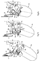
- the cleaning machine 1 comprises a body 2, a ventral tool 3 for bringing into a bin 4 waste located under the body, and on each side of the body 2, in front of the ventral tool 3, a lateral tool 5A and 5B having an oblong shape, for bringing the waste located on the sides of the body towards the ventral tool.
- the lateral tools are movable in translation in a direction transverse to the body 2, illustrated by the double arrows 6, between the extreme extended position shown and an extreme retracted position such as that shown in phantom in Figure 2, or that shown in figure 16.
- the machine 1 comprises means for automatically adjusting its working width as a function of the obstacles which may surround it.
- these means comprise, for the tool 5A, means for moving relative to the body 2 a tool holder 7, as well as elastic connection means 8 between the tool holder 7 and the lateral tool 5A, to make it resiliently movable relative to the tool holder.
- the elastic connection means 8 comprise two levers 9A and 9B each articulated at a first end on the tool holder 7, at the respective points 10A and 10B, and at a second end on the tool 5A, at the respective points 11A and 11B, the four points of articulation 10A , 10B, 11A, 11B forming the vertices of a deformable quadrilateral such that when the tool is moved relative to the tool holder, their relative angular orientation is modified at the same time as they are translated one relative to the other to the other (see Figure 15).
- An elastic link 12 is arranged between the levers 9A and 9B, so that the tool is spontaneously disposed at an angle relative to the body of the machine, while two stops 13A and 13B are provided on the support 7 to limit on each side the tool 5A displacements relative to tool holder 7.
- An electrical contact detector 14 is provided on the tool holder 7 to make it possible to detect whether the tool is, relative to the tool holder, in the internal limit position illustrated in FIG. 13, while another electrical contactor 15 is intended to detect the external limit position illustrated in FIG. 12.
- the position illustrated in FIG. 14 is the most transverse position possible that the tool 5A can adopt, which allows it to retract into the body of the machine 2, a flexible non-extensible link 16 being disposed between the body 2 and the lever 9B for making the tool 5A automatically adopt this arrangement in the extreme retracted position illustrated in FIG. 16, which offers compared to the variant shown in FIG. 2, the advantage of allowing the tool 5A to be entirely housed in the body 2 in the retracted position, while the volume necessary for this retraction is minimized.
- the two lateral tools 5A and 5B are similar, the tool holder 7 ′ is similar to the tool holder 7 and cooperates with the tool 5B by elastic connection means similar to the means 8, and more generally the machine 1 comprises each side of the similar means for the tool 5A and for the tool 5B.
- the tool holders 7 and 7 ′ are guided in translation by bars 17A and 17B transverse to the body 2 on which they are arranged head to tail, which offers the advantage of minimizing the bulk and saving the resources necessary for guide tools 5A and 5B in translation.
- the means for moving the tool holders relative to the body 2 are arranged above the tool holders and are connected to these by a vertical arm 18 (see FIG. 16).
- the lever 9A comprises two half-levers 19A and 19B adapted to slide relative to one another by means of rods 20A and 20B, the half-lever 19A being articulated on the tool holder, while the half-lever 19B is articulated on the tool 5A.
- Springs 21A and 21B are provided around the rods 20A and 20B in order to elastically apply the two half-levers 19A and 19B against each other, a proximity detector 22 being housed in the half-lever 19A to detect a spacing between the two half-levers, by detecting whether its end is in contact or not with the half-lever 19B.
- Proximity sensor 22 is used to detect if the tool has reached an extreme limit of movement relative to the tool holder: as seen in FIG. 14, if the tool is rotated 5A counterclockwise, while the lever 9B is in contact with the stop 13B, the displacement which will occur will cause a separation between the half-levers 19A and 19B, which will be detected by the proximity detector 22.
- Figure 3 there is illustrated the successive positions 23A, 23B, 23C and 23D occupied by the tool 5A when the machine 1 moves along the wall 24, as well as its direction of movement 25, the machine moving from right to left of the figure.
- the machine is also provided with safety means, the operation of which will now be explained in support of FIGS. 4 to 11.
- the tool 5A pivots by an angle ⁇ which causes it to reach the extreme limit of displacement detected by the sensor 22, which is connected to means of reflex reaction which act following this detection, on the one hand on means to stop the movement of the body of the machine relative to the surface to be cleaned, and on the other hand on the means to move the tool holder 5A so that they retract it as much as possible, as shown in Figure 6.
- the reflex reaction means also act, after the extreme limit for the arm 5A has been detected, on the means for stopping the movement of the body of the machine in order to re-authorize its movement when the extreme limit is no longer detected, that is to say when the tool 5A, after having been released from the obstacle 28, has been able to pivot in the opposite direction by an angle ⁇ (FIG. 6) and then after a certain period of time making it possible to clear the obstacle 28 the reflex reaction means act on the means to move the tool holder so that it comes out, and we find sacred in the position illustrated in FIG. 7.
- the reflex reaction means are also provided for the case shown in FIG. 8, in which the two tools 5A and 5B simultaneously encounter an obstacle such as the wall 30, and both pivot until the extreme limit of displacement (FIG. 9 ). In this case, after stopping the machine and retracting tools 5A and 5B as much as possible, they act on the means for moving the body of the machine to make it pivot, as shown in FIG. 11.
- the machine further comprises, means for automatically making the body 2 follow, on the surface to be cleaned, a predetermined cleaning trajectory as a function of the location of the obstacles and the possibilities of variation of its working width, so as to include only '' a minimum of changes in direction, the means for automatically adjusting the working width further comprising memory means for recording, for each lateral tool 5A and 5B, each position which must successively adopt the tool holder with respect to the body as a function of the position of the machine on the predetermined trajectory, as well as means connected to the means for making the trajectory follow the body of the machine, the storage means and the means for move the tool body, so that the latter bring the tool holder to the position it must adopt.
- Figures 21 to 23 each show a car on a train in the Paris metropolitan, Figures 21 and 22 showing two cars forming part of the same train, car 31 shown in Figure 21 being arranged at one end of this train, while the car 32 shown in Figure 22 is arranged in an intermediate position of the train.
- Each of the cars 31 and 32 has three rows of two pairs of seats arranged transversely, while the car 33 shown in FIG. 23, which is an intermediate car, has two rows of two pairs of transverse seats while at each end of the car are arranged longitudinally of other seats.
- the machine is made to follow a trajectory along the vehicle on one side from one end to the other, then along the opposite side in the opposite direction, the trajectory then comprising a central section traversed in the same sense as the section bordering the first side.
- the first section 38 is rectilinear, and runs along the side located on the bottom of the figure, the trajectory then presents a U-turn then begins to follow the opposite side of the car but an extremely obstacle important being under the seat 39, the trajectory avoids this seat then continues while being practically rectilinear, with the exception of a small detour to avoid the obstacle located under the seat 40 then the trajectory ends in the rectilinear central section 41.
- the machine 1 has been able to pass under the seats of the vehicles 31 to 33 since it has a particularly reduced height dimension, and that the amplitude of the variations in its working width enables it to avoid the majority obstacles, and in particular the bars 45 of vehicles 31 and 32.
- the machine 1 is particularly compact, for example it may be noted that its height is 25 cm, the width of the body 40 cm while the maximum cleaning width is 82.5 cm while the length of the craft is 70 cm.
- the ventral tool 3 is formed by cylindrical brushes 46 and 47, the brush 47 performing a longitudinal brushing of the surface to be cleaned;
- the body 2 is mobile thanks to two powertrains 48A and 48B arranged on the respective sides of the body, each comprising a motor 49 and a wheel 50;
- a suction assembly is provided in compartment 51, an electronic assembly is arranged in compartment 52 and batteries in compartment 53, below which there is a idler wheel 54, while a handle 55 is provided on the inside. 'before the craft.
- the lateral tool 5A to which the tool 5B is similar, is mounted in detail in FIGS. 18 to 20.
- It forms an oblong brushing assembly comprising as brush a belt 57 provided with bristles 58 on its outer profile while its inner profile is adapted to cooperate with rotary pulleys 58 to 60, said bristles being implanted obliquely on the belt.
- the pulleys 58 to 60 are mounted on an oblong support 61 on which a motor 62 is also installed to drive the pulley 58, this motor being connected to the pulley 58 by an Oldham seal 63 and a reduction gear 64, a cover 65 being provided above the engine while a hood 66 is provided above the Oldham joint and the reducer.
- Pivots 67A and 67B are provided on the support, for mounting the lever 9A and the lever 9B respectively.
Abstract
Description
L'invention se rapporte à un engin pour nettoyer une surface présentant des obstacles.The invention relates to a device for cleaning a surface having obstacles.
EP-A-0.087.936 et FR-A-2.297.286 décrivent un engin dont les moyens pour déplacer un porte-outil de nettoyage par rapport au corps de l'engin permettent non seulement d'amener l'outil à une position préfixée, en fonction d'un ordre donné par le conducteur de l'engin, mais aussi d'assurer un ajustement passif de la largeur de travail de l'engin en fonction des obstacles, grâce à une certaine "élasticité" hydraulique ou pneumatique. EP-A-0.087.936 décrit en outre des moyens de liaison élastique entre une brosse (l'outil latéral) et un porte-brosse, prévus pour maintenir le brosse à l'angle de balayage approprié ; ainsi que des moyens de réaction réflexe à un obstacle, comportant notamment une barre sensitive.EP-A-0.087.936 and FR-A-2.297.286 describe a machine the means of which for moving a cleaning tool holder relative to the body of the machine not only make it possible to bring the tool to a prefixed position , according to an order given by the operator of the machine, but also to ensure a passive adjustment of the working width of the machine as a function of obstacles, thanks to a certain hydraulic or pneumatic "elasticity". EP-A-0.087.936 further describes means of elastic connection between a brush (the lateral tool) and a brush holder, designed to maintain the brush at the appropriate sweep angle; as well as means of reflex reaction to an obstacle, comprising in particular a sensitive bar.
L'invention vise à rendre plus aisé le pilotage de ces engins.The invention aims to make it easier to pilot these machines.
A cet effet, elle propose un engin pour nettoyer une surface présentant des obstacles, comportant un corps muni sur au moins un côté d'un outil latéral et, pour chaque outil latéral, des moyens pour déplacer par rapport au corps un porte-outil, ainsi que des moyens de liaison élastique entre le porte-outil et l'outil latéral, pour rendre l'outil latéral mobile élastiquement par rapport au porte-outil ; caractérisé en ce que lesdits moyens pour déplacer par rapport au corps un porte-outil ainsi que lesdits moyens de liaison élastique entre le porte-outil et l'outil latéral, font tous deux partie de moyens pour ajuster automatiquement la largeur de travail de l'engin en fonction des obstacles l'avoisinant éventuellement, de telle sorte qu'on peut le déplacer sur ladite surface selon une trajectoire comportant un minimum de changements de direction, lesdits moyens de liaison élastique entre le porte outil et l'outil latéral procurant un niveau passif d'ajustement automatique de la largeur de travail, lesdits moyens pour déplacer par rapport au corps un porte-outil procurant un niveau actif d'ajustement automatique de la largeur de travail.To this end, it provides a device for cleaning a surface presenting obstacles, comprising a body provided on at least one side with a lateral tool and, for each lateral tool, means for moving relative to the body a tool holder, as well as elastic connection means between the tool holder and the lateral tool, to make the lateral tool resiliently movable relative to the tool holder; characterized in that said means for moving relative to the body a tool holder as well as said elastic connection means between the tool holder and the lateral tool, are both part of means for automatically adjusting the working width of the depending on the obstacles possibly surrounding it, so that it can be moved over said surface along a trajectory comprising a minimum of changes in direction, said means of elastic connection between the tool holder and the lateral tool providing a level passive automatic adjustment of the working width, said means for moving relative to the body a tool holder providing an active level of adjustment automatic working width.
Ainsi, à l'inverse des engins de nettoyage connus jusqu'ici, l'engin selon l'invention peut se déplacer selon une trajectoire comportant un minimum de changements de direction, et on peut par exemple suivre une paroi présentant des irrégularités sans avoir à faire suivre à l'engin une trajectoire ayant les mêmes irrégularités, c'est au contraire la largeur de travail de l'engin qui s'adaptera à ces irrégularités pendant qu'on déplace l'engin suivant une direction que l'on peut garder constante tant que l'amplitude des variations de la largeur de travail permet d'absorber les irrégularités.Thus, unlike the cleaning machines known hitherto, the machine according to the invention can move along a trajectory comprising a minimum of changes in direction, and one can for example follow a wall having irregularities without having to make the machine follow a trajectory having the same irregularities, it is on the contrary the working width of the machine which will adapt to these irregularities while moving the machine in a direction that we can keep constant as long as the amplitude of the variations in the working width makes it possible to absorb the irregularities.
L'invention offre notamment l'avantage de réduire la fatigue de l'opérateur s'il est à pilotage manuel, et dans le cas d'un engin se déplaçant de manière autonome, c'est-à-dire un robot de nettoyage, de moins solliciter le dispositif commandant son déplacement.The invention notably offers the advantage of reducing the operator's fatigue if he is manually piloted, and in the case of a machine moving independently, that is to say a cleaning robot, reduce the stress on the device controlling its movement.
En outre, dans certaines configurations telle qu'une surface bordée par des parois se resserrant et s'écartant, l'engin selon l'invention permet de nettoyer la surface en une passe au lieu de deux passes beaucoup plus sinueuses ; et plus généralement, d'obtenir un meilleur rapport surface nettoyée/distance parcourue qu'avec les engins classiques.In addition, in certain configurations such as a surface bordered by tightening and moving apart walls, the machine according to the invention makes it possible to clean the surface in one pass instead of two much more sinuous passes; and more generally, to obtain a better ratio of cleaned surface area / distance traveled than with conventional vehicles.
Du fait qu'on dispose, pour ajuster la largeur de travail, de deux niveaux : un niveau d'ajustement passif procuré par les moyens élastiques, et un niveau d'ajustement actif fourni par les moyens pour déplacer le porte-outil, on peut réduire le nombre d'intervention des moyens pour déplacer le porte-outil, et en outre rattraper certaines imprécisions de positionnement.Because there are two levels for adjusting the working width: a passive adjustment level provided by the elastic means, and an active adjustment level provided by the means for moving the tool holder, it is possible to reduce the number of intervention means to move the tool holder, and also make up for certain positioning inaccuracies.
Selon des caractéristiques préférées, lesdits moyens pour ajuster automatiquement la largeur de travail comportent en outre, pour chaque outil latéral :
- des moyens de détection pour détecter si l'outil est, par rapport au porte-outil, dans une position interne limite correspondant à un déplacement maximum autorisé vers le corps d'engin ;
- des moyens d'action, reliés aux moyens de détection, pour agir, quand est détectée ladite position interne limite, sur lesdits moyens pour déplacer par rapport au corps un porte-outil, afin de rapprocher le porte-outil du corps d'une distance préfixée.
- detection means for detecting whether the tool is, relative to the tool holder, in an internal limit position corresponding to a maximum authorized displacement towards the body of the machine;
- action means, connected to the detection means, for acting, when said limit internal position is detected, on said means for moving relative to the body a tool holder, in order to bring the tool holder closer to the body by a distance prefixed.
Ainsi, lorsque l'emplacement des obstacles qui environnent l'engin fait que l'outil latéral se rapproche de l'engin jusqu'à sortir de la zone d'élasticité autorisée, on déplace cette zone d'élasticité afin qu'il puisse se déplacer passivement dans la nouvelle zone.Thus, when the location of the obstacles which surround the machine causes the lateral tool to approach the machine until it leaves the authorized elasticity zone, this elasticity zone is moved so that it can be passively move to the new area.
On peut se servir de ces caractéristiques pour ajuster directement la largeur de travail de l'engin ou bien, lorsque l'on a prévu d'autres moyens pour commander la largeur de travail de l'outil (voir ci-dessous), on peut les utiliser comme moyens de sécurité permettant d'éviter que l'outil latéral ne subisse des contraintes trop importantes.These characteristics can be used to directly adjust the working width of the machine or, when other means have been provided for controlling the working width of the tool (see below), use them as safety means to prevent the lateral tool from being subjected to excessive stresses.
Selon d'autres caractéristiques préférées, lesdits moyens pour ajuster automatiquement la largeur de travail comportent en outre, pour chaque outil latéral, des deuxièmes moyens de détection pour détecter si l'outil est par rapport au porte-outil dans une position externe limite correspondant à un déplacement maximum autorisé vers l'opposé du corps d'engin, lesdits moyens d'action étant également reliés auxdits deuxièmes moyens de détection, et agissant quand est détectée la position externe limite, sur les moyens pour déplacer le porte-outil afin de l'éloigner du corps d'une distance préfixée.According to other preferred features, said means for automatically adjusting the working width further comprises, for each lateral tool, second detection means for detecting whether the tool is relative to the tool holder in an external limit position corresponding to a maximum authorized movement towards the opposite from the body of the machine, said means of action also being connected to said second detection means, and acting when the limit external position is detected, on the means for moving the tool holder in order to move it away from the body of a prefixed distance.
Lorsque l'engin présente également ces caractéristiques, on peut entièrement réaliser l'ajustement de la largeur de travail avec les moyens de détection et les moyens d'action.When the machine also has these characteristics, it is entirely possible to adjust the working width with the detection means and the action means.
Dans un mode de réalisation de l'engin, il comporte des moyens pour faire suivre automatiquement au corps d'engin sur ladite surface, une trajectoire de nettoyage prédéterminée en fonction de l'emplacement des obstacles et des possibilités de variations de la largeur de travail de l'engin, pour ne comporter qu'un minimum de changements de direction.In one embodiment of the machine, it comprises means for automatically making the body of the machine, on said surface, follow a predetermined cleaning trajectory as a function of the location of the obstacles and of the possibilities of variations in the working width. of the machine, to include only a minimum of changes of direction.
Selon des caractéristiques préférées de ce mode de réalisation, les moyens pour ajuster automatiquement la largeur de travail comportent en outre, des moyens de mémorisation pour enregistrer, pour chaque outil latéral, chaque position que doit adopter successivement le porte-outil par rapport au corps en fonction de la position du corps d'engin sur ladite trajectoire prédéterminée, et des moyens reliés auxdits moyens pour faire suivre la trajectoire au corps d'engin, auxdits moyens de mémorisation et auxdits moyens pour déplacer le porte-outil, pour que ces derniers amènent le porte-outil à la position qu'il doit adopter.According to preferred features of this embodiment, the means for automatically adjusting the working width further comprise storage means for recording, for each lateral tool, each position which the tool holder must successively adopt relative to the body in function of the position of the body of the machine on said predetermined trajectory, and of the means connected to said means for making the trajectory follow to the body of machine, to said storage means and to said means for moving the tool holder, so that the latter bring the tool holder in the position it must adopt.
Avec ces caractéristiques, étant donné qu'on sait déjà quelle est la largeur de travail à donner à l'engin, on obtient un temps de réaction très rapide pour l'ajustement en largeur, de telle sorte que la vitesse de déplacement du corps d'engin peut être relativement importante.With these characteristics, since we already know what is the working width to give to the machine, we obtain a very fast reaction time for the width adjustment, so that the speed of movement of the machine body can be relatively large.
Il est naturellement possible, en fonction des besoins, de combiner les caractéristiques qui viennent d'être exposées, aux moyens de détection et d'action exposés un peu plus haut, pour la sécurité de l'engin.It is naturally possible, depending on the needs, to combine the characteristics which have just been exposed, with the detection and action means set out above, for the safety of the machine.
Selon des caractéristique préférées de l'engin selon l'invention, il comporte des moyens de sécurité comportant :
- pour chaque outil latéral, des moyens de détection de blocage, pour détecter si l'outil atteint par rapport au porte-outil une limite extrême de déplacement vers le corps d'engin ;
- des moyens de réaction réflexe, reliés aux moyens de détection de blocage, pour agir quand est détectée une dite limite extrême, d'une part sur des moyens pour arrêter le déplacement du corps d'engin par rapport à la surface à nettoyer, et d'autre part sur les moyens pour déplacer le porte-outil concerné, afin qu'ils le rétractent au maximum.
- for each lateral tool, blocking detection means, for detecting whether the tool reaches in relation to the tool holder an extreme limit of movement towards the machine body;
- reflex reaction means, connected to the blocking detection means, for acting when a said extreme limit is detected, on the one hand, on means for stopping the movement of the body of the machine relative to the surface to be cleaned, and d on the other hand on the means to move the tool holder concerned, so that they retract it as much as possible.
On évite ainsi que l'engin ne soit coincé par un obstacle imprévu, en risquant de détériorer l'outil latéral.This prevents the machine from being trapped by an unforeseen obstacle, risking damaging the lateral tool.
De préférence, lesdits moyens de réaction réflexe agissent en outre, après qu'ait été détectée une seule limite extrême, sur les moyens pour arrêter le déplacement du corps d'engin afin de réautoriser le déplacement du corps d'engin quand ladite limite extrême de déplacement n'est plus détectée, puis sur les moyens pour déplacer le porte-outil afin qu'il ressorte.Preferably, said reflex reaction means also act, after a single extreme limit has been detected, on the means for stopping the movement of the machine body in order to re-authorize the movement of the machine body when said extreme limit of displacement is no longer detected, then on the means for displacing the tool holder so that it emerges.
On rend ainsi l'engin capable de surmonter par lui-même une situation de coincement par un obstacle purement latéral.This makes the machine capable of overcoming by itself a situation of jamming by a purely lateral obstacle.
Selon d'autres caractéristiques préférées, pour un engin comportant deux outils latéraux similaires, respectivement sur chaque côté du corps d'engin, ainsi que des moyens pour déplacer automatiquement le corps d'engin, lesdits moyens de réaction réflexe agissent, après qu'ait été détectée une limite extrême pour chaque outil latéral, sur les moyens pour déplacer automatiquement le corps d'engin afin de le faire pivoter.According to other preferred characteristics, for a machine comprising two similar lateral tools, respectively on each side of the body of the machine, as well as means for automatically moving the body of the machine, said reflex reaction means acting, after an extreme limit has been detected for each lateral tool, on the means for automatically moving the body of the machine in order to rotate it.
Si les deux outils latéraux ont rencontré un obstacle, c'est que le robot se trouve face à un obstacle tel qu'un mur, il doit donc pivoter pour s'en dégager.If the two lateral tools have encountered an obstacle, this means that the robot is facing an obstacle such as a wall, so it must pivot to free itself from it.
L'invention concerne également, sous un deuxième aspect, un procédé de nettoyage d'une surface présentant des obstacles, dans lequel on utilise un engin tel que précédemment exposé.The invention also relates, in a second aspect, to a method of cleaning a surface having obstacles, in which a machine is used as previously exposed.
Ce procédé est avantageusement appliqué au nettoyage du sol d'un véhicule de transport en commun.This process is advantageously applied to cleaning the floor of a public transport vehicle.
Selon des caractéristiques préférées du procédé, on fait suivre à l'engin une trajectoire longeant le véhicule sur un côté d'une extrémité à l'autre, puis longeant le côté opposé en sens inverse, ladite trajectoire comportant ensuite un tronçon central parcouru dans le même sens que le tronçon bordant le premier côté, l'engin utilisé comportant des moyens pour faire suivre automatiquement au corps d'engin ladite trajectoire, cet engin ayant une dimension en hauteur lui permettant de passer sous les sièges du véhicule tandis que l'amplitude des variations de sa largeur de travail lui permet de nettoyer le sol du véhicule en suivant ledit parcours.According to preferred characteristics of the method, the machine is made to follow a trajectory running along the vehicle on one side from one end to the other, then along the opposite side in the opposite direction, said trajectory then comprising a central section traversed in the same direction as the section bordering the first side, the machine used comprising means for making the machine body automatically follow said trajectory, this machine having a height dimension enabling it to pass under the seats of the vehicle while the amplitude variations in its working width allow it to clean the vehicle floor by following said route.
Ce procédé offre l'avantage de permettre de nettoyer de façon particulièrement efficace le véhicule, et dans le cas où le véhicule est une voiture d'un train tel que le métropolitain parisien, il offre l'avantage de se terminer à l'extrémité opposée de la voiture par laquelle il a commencé, de telle sorte que l'opérateur qui déplace l'engin d'une voiture à l'autre doit simplement parcourir la distance correspondant au raccordement entre voitures, sans avoir à parcourir toute la longueur de la voiture.This method offers the advantage of making it possible to clean the vehicle in a particularly effective way, and in the case where the vehicle is a car of a train such as the Paris metropolitan, it offers the advantage of ending at the opposite end. of the car it started with, so that the operator who moves the machine from one car to another must simply travel the distance corresponding to the connection between cars, without having to travel the entire length of the car .
L'exposé de l'invention sera maintenant poursuivi par la description d'exemples de réalisation, faite ci-après à titre illustratif et non limitatif en référence aux dessins annexés, sur lesquels :
- la figure 1 est une vue schématique en élévation d'un engin de nettoyage conforme à l'invention ;
- la figure 2 est une vue de dessus de cet engin ;
- la figure 3 illustre schématiquement le comportement de l'engin quand il se déplace le long d'une paroi présentant des irrégularités ;
- les figures 4 à 7 illustrent le comportement de l'engin quand il rencontre un obstacle latéral susceptible de le coincer par l'un des outils latéraux ;
- les figures 8 à 11 illustrent le comportement de l'engin quand il rencontre un obstacle le coinçant par les deux outils latéraux ;
- les figures 12 à 14 montrent par une vue de dessus prise au niveau du porte-outil, les moyens de liaison élastique reliant l'outil latéral 5A de l'engin à son porte-outil, respectivement en position externe limite, en position interne limite, et en position extrême de déplacement vers le corps d'engin ;
- la figure 15 représente l'outil latéral, en trait plein pour la position de la figure 12, en trait interrompu pour celle de la figure 13, et en trait mixte pour celle de la figure 14 ;
- la figure 16 est une coupe partielle en plan de l'engin, montrant les tiges de guidage du porte-outil, et la position qu'adopte l'outil quand il est rentré dans le corps d'engin ;
- la figure 17 est une coupe en plan du
levier 9A des moyens de liaison élastique outil - porte-outil ; - la figure 18 illustre de façon plus détaillée l'un des outils latéraux de l'engin, suivant une coupe prise suivant la ligne A-A de la figure 2 ;
- la figure 19 est la coupe indiquée en B-B sur la figure 18 ;
- la figure 20 est une vue de dessous de cet outil latéral ; et
- les figures 21 à 23 sont des coupes en plan de trois sortes de voiture du métropolitain parisien, montrant la trajectoire qu'y suit l'engin pour en nettoyer le sol.
- Figure 1 is a schematic elevational view of a cleaning machine according to the invention;
- Figure 2 is a top view of this machine;
- Figure 3 schematically illustrates the behavior of the machine when it moves along a wall with irregularities;
- Figures 4 to 7 illustrate the behavior of the machine when it encounters a lateral obstacle capable of jamming it by one of the lateral tools;
- Figures 8 to 11 illustrate the behavior of the machine when it encounters an obstacle wedging it by the two lateral tools;
- Figures 12 to 14 show in a top view taken at the tool holder, the elastic connection means connecting the
lateral tool 5A of the machine to its tool holder, respectively in external limit position, in internal limit position , and in the extreme position of movement towards the machine body; - FIG. 15 shows the lateral tool, in solid lines for the position of FIG. 12, in broken lines for that of FIG. 13, and in dashed lines for that of FIG. 14;
- FIG. 16 is a partial plan section of the machine, showing the guide rods of the tool holder, and the position which the tool takes when it has entered the body of the machine;
- Figure 17 is a plan section of the
lever 9A of the elastic tool - tool holder connection means; - Figure 18 illustrates in more detail one of the side tools of the machine, in a section taken along line AA of Figure 2;
- Figure 19 is the section indicated in BB on Figure 18;
- Figure 20 is a bottom view of this side tool; and
- Figures 21 to 23 are sections in plan of three kinds of car of the Parisian metropolitan, showing the trajectory which the machine follows there to clean the ground.
L'engin de nettoyage 1 comporte un corps 2, un outil ventral 3 pour amener dans un bac 4 des déchets se trouvant sous le corps, et de chaque côté du corps 2, en avant de l'outil ventral 3, un outil latéral 5A et 5B présentant une forme oblongue, pour ramener vers l'outil ventral les déchets se trouvant sur les côtés du corps.The
Les outils latéraux sont mobiles en translation suivant une direction transversale au corps 2, illustrée par les flèches doubles 6, entre la position sortie extrême représentée et une position rétractée extrême telle que celle montrée en trait mixte sur la figure 2, ou celle montrée sur la figure 16.The lateral tools are movable in translation in a direction transverse to the
Ainsi, dans chaque position, ils gardent leur orientation en biais suivant des directions qui forment un V dont la pointe se situe dans le corps 2, de telle sorte qu'ils continuent à ramener les déchets vers l'outil ventral 3 quelle que soit la position qu'on leur a donnée pour faire varier la largeur de nettoyage de l'engin 1.Thus, in each position, they keep their orientation at an angle in directions which form a V whose point is located in the
Conformément à l'invention, l'engin 1 comporte des moyens pour ajuster automatiquement sa largeur de travail en fonction des obstacles l'avoisinant éventuellement.In accordance with the invention, the
Comme on le voit sur les figures 12 à 14, ces moyens comportent, pour l'outil 5A, des moyens pour déplacer par rapport au corps 2 un porte outil 7, ainsi que des moyens de liaison élastique 8 entre le porte-outil 7 et l'outil latéral 5A, pour le rendre mobile élastiquement par rapport au porte-outil.As can be seen in FIGS. 12 to 14, these means comprise, for the
Les moyens de liaison élastique 8 comportent deux leviers 9A et 9B articulés chacun à une première extrémité sur le porte-outil 7, aux points respectifs 10A et 10B, et à une deuxième extrémité sur l'outil 5A, aux points respectifs 11A et 11B, les quatre points d'articulation 10A, 10B, 11A, 11B formant les sommets d'un quadrilatère déformable tel que lorsque l'on déplace l'outil par rapport au porte-outil, on modifie leur orientation angulaire relative en même temps qu'on les translate l'un par rapport à l'autre (voir figure 15).The elastic connection means 8 comprise two
On observera que les côtés du quadrilatère correspondant à un levier, c'est-à-dire les côtés situés entre les points 10A, 11A et 10B, 11B, ont une longueur similaire, tandis que les deux autres côtés opposés, c'est-à-dire les côtés situés entre les points 10A, 10B et 11A, 11B ont une longueur différente, la longueur du côté 11A, 11B étant supérieure à celle du côté 10A, 10B.It will be observed that the sides of the quadrilateral corresponding to a lever, that is to say the sides situated between the
Un lien élastique 12 est disposé entre les leviers 9A et 9B, afin que l'outil soit spontanément disposé en biais par rapport au corps d'engin, tandis que deux butées 13A et 13B sont prévues sur le support 7 pour limiter de chaque côté les déplacements de l'outil 5A par rapport au porte-outil 7.An
Un détecteur de contact électrique 14 est prévu sur le porte-outil 7 pour permettre de détecter si l'outil est, par rapport au porte-outil, dans la position limite interne illustrée sur la figure 13, tandis qu'un autre contacteur électrique 15 est prévu pour détecter la position limite externe illustrée sur la figure 12.An
La position illustrée sur la figure 14 est la position la plus transversale possible que peut adopter l'outil 5A, qui lui permet de se rétracter dans le corps de l'engin 2, un lien souple non extensible 16 étant disposé entre le corps 2 et le levier 9B pour faire adopter automatiquement à l'outil 5A cette disposition dans la position rétractée extrême qu'illustre la figure 16, ce qui offre par rapport à la variante montrée sur la figure 2, l'avantage de permettre le loger entièrement l'outil 5A dans le corps 2 en position rétractée, alors qu'est minimisé le volume nécessaire à cette rétractation.The position illustrated in FIG. 14 is the most transverse position possible that the
Les deux outils latéraux 5A et 5B sont similaires, le porte-outil 7′ est similaire au porte-outil 7 et coopère avec l'outil 5B par des moyens de liaison élastique similaires aux moyens 8, et plus généralement l'engin 1 comporte de chaque côté des moyens similaires pour l'outil 5A et pour l'outil 5B.The two
Les porte-outils 7 et 7′ sont guidés en translation par des barres 17A et 17B transversales au corps 2 sur lesquels elles sont disposées tête-bêche, ce qui offre l'avantage de minimiser l'encombrement et d'économiser les moyens nécessaires pour guider les outils 5A et 5B en translation.The
Les moyens pour déplacer les porte-outils par rapport au corps 2 (non représentés) sont disposés au-dessus des porte-outils et sont reliés à ceux-ci par un bras vertical 18 (voir figure 16).The means for moving the tool holders relative to the body 2 (not shown) are arranged above the tool holders and are connected to these by a vertical arm 18 (see FIG. 16).
Ainsi qu'on le voit sur la figure 17, le levier 9A comporte deux demi-leviers 19A et 19B adaptés à coulisser l'un par rapport à l'autre grâce à des tiges 20A et 20B, le demi-levier 19A étant articulé sur le porte-outil, tandis que le demi-levier 19B est articulé sur l'outil 5A. Des ressorts 21A et 21B sont prévus autour des tiges 20A et 20B afin d'appliquer élastiquement les deux demi-leviers 19A et 19B l'un contre l'autre, un détecteur de proximité 22 étant logé dans le demi-levier 19A pour détecter un écartement entre les deux demi-leviers, en détectant si son extrémité est en contact ou non avec le demi-levier 19B.As can be seen in FIG. 17, the
Le détecteur de proximité 22 sert à détecter si l'outil a atteint par rapport au porte-outil une limite extrême de déplacement vers le corps d'engin : comme on le voit sur la figure 14, si l'on fait pivoter l'outil 5A dans le sens inverse des aiguilles d'une montre, alors que le levier 9B est en contact avec la butée 13B, le déplacement qui se produira provoquera un écartement entre les demi-leviers 19A et 19B, que détectera le détecteur de proximité 22.
Sur la figure 3, on a illustré les positions successives 23A, 23B, 23C et 23D qu'occupe l'outil 5A quand l'engin 1 se déplace le long de la paroi 24, ainsi que sa direction de déplacement 25, l'engin se déplaçant de la droite vers la gauche de la figure.In Figure 3, there is illustrated the
Dans les positions 23A, 23B et 23C, l'outil est resté dans la zone d'élasticité 26 sans que soit atteinte sa limite intérieure autorisée, correspondant à la position montrée sur la figure 13.In positions 23A, 23B and 23C, the tool has remained in the
Entre les positions 23C et 23D, cette position a été atteinte, et les moyens d'action reliés au détecteur 14 que comporte l'engin, ont agi sur les moyens pour déplacer le porte-outil afin de la rapprocher du corps d'un incrément, c'est-à-dire d'une certaine distance préfixée, de telle sorte que la zone d'élasticité s'est déplacée pour devenir la zone 27.Between positions 23C and 23D, this position has been reached, and the means of action connected to the
A l'inverse, si la paroi s'était écartée du corps de l'outil au lieu de s'en rapprocher, on serait arrivé dans la position illustrée sur la figure 12 dans laquelle le bras 9A actionne le détecteur de contact 15, auquel sont reliés ces moyens d'action, qui auraient agi sur les moyens pour déplacer le porte-outil afin de l'éloigner du corps de ce même incrément.Conversely, if the wall had moved away from the body of the tool instead of approaching it, we would have arrived in the position illustrated in FIG. 12 in which the
On notera que malgré les irrégularités de la paroi 24, la direction de déplacement 25 est rectiligne.Note that despite the irregularities of the
L'engin est également muni de moyens de sécurité dont le fonctionnement va maintenant être expliqué à l'appui des figures 4 à 11.The machine is also provided with safety means, the operation of which will now be explained in support of FIGS. 4 to 11.
Lorsque l'engin 1 arrive sur l'obstacle 28, comme le montre la figure 4, l'outil 5A pivote d'un angle α qui le fait parvenir jusqu'à la limite extrême de déplacement que détecte le capteur 22, qui est relié à des moyens de réaction réflexe qui agissent à la suite de cette détection, d'une part sur des moyens pour arrêter le déplacement du corps d'engin par rapport à la surface à nettoyer, et d'autre part sur les moyens pour déplacer le porte-outil 5A afin qu'ils le rétractent au maximum, comme le montre la figure 6.When the
Les moyens de réaction réflexe agissent en outre, après qu'ait été détectée la limite extrême pour le bras 5A, sur les moyens pour arrêter le déplacement du corps d'engin afin de réautoriser son déplacement quand la limite extrême n'est plus détectée, c'est-à-dire quand l'outil 5A, après avoir été dégagé de l'obstacle 28, a pu pivoter en sens inverse d'un angle β (figure 6) puis au bout d'un certain laps de temps permettant de franchir l'obstacle 28 les moyens de réaction réflexe agissent sur les moyens pour déplacer le porte-outil afin qu'il ressorte, et on se retrouve dans la position illustrée sur la figure 7.The reflex reaction means also act, after the extreme limit for the
Les moyens de réaction réflexe sont également prévus pour le cas montré sur la figure 8, dans lequel les deux outils 5A et 5B rencontrent simultanément un obstacle tel que la paroi 30, et pivotent tous deux jusqu'à la limite extrême de déplacement (figure 9). Dans ce cas, après avoir arrêté l'engin et rétracté au maximum les outils 5A et 5B, ils agissent sur les moyens pour déplacer le corps d'engin pour le faire pivoter, comme le montre la figure 11.The reflex reaction means are also provided for the case shown in FIG. 8, in which the two
L'engin comporte en outre, des moyens pour faire suivre automatiquement au corps 2 sur la surface à nettoyer, une trajectoire de nettoyage prédéterminée en fonction de l'emplacement des obstacles et des possibilités de variation de sa largeur de travail, pour ne comporter qu'un minimum de changements de direction, les moyens pour ajuster automatiquement la largeur de travail comportant en outre des moyens de mémorisation pour enregistrer, pour chaque outil latéral 5A et 5B, chaque position que doit adopter susccessivement le porte-outil par rapport au corps en fonction de la position de l'engin sur la trajectoire prédéterminée, ainsi que des moyens reliés aux moyens pour faire suivre la trajectoire au corps d'engin, aux moyens de mémorisation et aux moyens pour déplacer le corps d'outil, pour que ces derniers amènent le porte-outil à la position qu'il doit adopter.The machine further comprises, means for automatically making the
Dans ces conditions, dans un but de simplification, il est possible de supprimer le capteur 15 et les moyens d'action correspondants, tandis que le capteur 14 offre simplement une certaine sécurité évitant que l'outil 5A ne supporte des contraintes trop importantes : c'est essentiellement en fonction des données enregistrées que seront déplacés les porte-outils, mais si à la suite d'imprécisions dans le suivi de la trajectoire l'outil est trop éloigné du corps 2, on le rentre automatiquement d'une quantité appropriée.Under these conditions, for the sake of simplification, it is possible to eliminate the
Les figures 21 à 23 montrent chacune une voiture d'une rame du métropolitain parisien, les figures 21 et 22 montrant deux voitures faisant partie d'une même rame, la voiture 31 montrée sur la figure 21 étant disposée à l'une des extrémités de cette rame, tandis que la voiture 32 montrée sur la figure 22 est disposée dans une position intermédiaire de la rame.Figures 21 to 23 each show a car on a train in the Paris metropolitan, Figures 21 and 22 showing two cars forming part of the same train,
Chacune des voitures 31 et 32 comporte trois rangées de deux paires de sièges disposés transversalement, tandis que la voiture 33 montrée sur la figure 23, qui est une voiture intermédiaire, comporte deux rangées de deux paires de sièges transversaux tandis qu'à chaque extrémité de la voiture sont disposés longitudinalement d'autres sièges.Each of the
Dans chacun des trois exemples illustrés, on fait suivre à l'engin une trajectoire longeant le véhicule sur un côté d'une extrémité à l'autre, puis longeant le côté opposé en sens inverse, la trajectoire comportant ensuite un tronçon central parcouru dans le même sens que le tronçon bordant le premier côté.In each of the three examples illustrated, the machine is made to follow a trajectory along the vehicle on one side from one end to the other, then along the opposite side in the opposite direction, the trajectory then comprising a central section traversed in the same sense as the section bordering the first side.
Dans le cas de la voiture 31, on a commencé par longer le véhicule en bordant la paroi située sur le haut du dessin en suivant une trajectoire pratiquement rectiligne, on a simplement fait un détour pour éviter un obstacle important situé sous le siège 34. Après ce premier tronçon 35 sensiblement rectiligne, l'engin a fait demi-tour pour longer en sens inverse le côté opposé de la voiture 31, et là il a pu suivre une trajectoire rectiligne, et à la fin de ce tronçon rectiligne 36, il a fait demi-tour pour circuler au centre de la voiture en suivant un tronçon rectiligne 37.In the case of the
Dans le cas de la voiture 32, le premier tronçon 38 est rectiligne, et longe le côté se trouvant sur le bas de la figure, la trajectoire présente ensuite un demi-tour puis commence à longer le côté opposé de la voiture mais un obstacle extrêmement important se trouvant sous le siège 39, la trajectoire évite ce siège puis se poursuit en étant pratiquement rectiligne, à l'exception d'un petit détour pour éviter l'obstacle situé sous le siège 40 puis la trajectoire se termine par le tronçon central rectiligne 41.In the case of
Pour ce qui est de la voiture 33, l'on est parti en position centrale de l'une des extrémités compte tenu de la dispositions des sièges aux extrémités, puis l'on a suivi de chaque côté un tronçon rectiligne tandis que dans le tronçon central 42 on a dû faire des détours pour éviter les barres 43 ainsi qu'un obstacle situé sous le siège 44, avant de terminer à l'autre extémité entre les sièges qui s'y trouvent.As for the
On observera que ces trajectoires, qui ont été suivies automatiquement par l'engin, offrent l'avantage de se commencer et de se terminer à des extrémités opposées de la voiture, de telle sorte que l'opérateur qui doit déplacer l'engin d'une voiture à l'autre doit simplement franchir le raccordement entre les voitures, il n'a pas à parcourir avec l'engin toute la longueur d'une voiture.It will be observed that these trajectories, which have been automatically followed by the vehicle, have the advantage of starting and ending at opposite ends of the car, so that the operator who has to move the vehicle from one car to another just has to cross the connection between cars, it doesn't have to travel with the machine the entire length of a car.
On notera que l'engin 1 a pu passer sous les sièges des véhicules 31 à 33 étant donné qu'il a une dimension en hauteur particulièrement réduite, et que l'amplitude des variations de sa largeur de travail lui permet d'éviter la majorité des obstacles, et notamment les barres 45 des véhicules 31 et 32.It will be noted that the
Plus généralement, l'engin 1 est particulièrement compact, à titre d'exemple on pourra noter que sa hauteur est de 25 cm, la largeur du corps de 40 cm tandis que la largeur maximale de nettoyage est de 82,5 cm tandis que la longueur de l'engin est de 70 cm.More generally, the
L'outil ventral 3 est formé par des brosses cylindriques 46 et 47, la brosse 47 réalisant un brossage longitudinal de la surface à nettoyer ; le corps 2 est mobile grâce à deux groupes motopropulseurs 48A et 48B disposés sur les côtés respectifs du corps, comportant chacun un moteur 49 et une roue 50 ; un ensemble d'aspiration est prévu dans le compartiment 51, un ensemble électronique est disposé dans le compartiment 52 et des batteries dans le compartiment 53, en-dessous duquel se trouve une roue folle 54, tandis qu'une poignée 55 est prévue à l'avant de l'engin.The
L'outil latéral 5A, auquel est similaire l'outil 5B, est monté en détail sur les figures 18 à 20.The
Il forme un ensemble de brossage oblong comportant comme brosse une courroie 57 munie de poils 58 sur son profil extérieur tandis que son profil intérieur est adapté à coopérer avec des poulies rotatives 58 à 60, lesdits poils étant implantés de manière oblique sur la courroie.It forms an oblong brushing assembly comprising as brush a
Les poulies 58 à 60 sont montées sur un support oblong 61 sur lequel est également installé un moteur 62 pour entraîner la poulie 58, ce moteur étant relié à la poulie 58 par un joint de Oldham 63 et un réducteur 64, un capot 65 étant prévu au-dessus du moteur tandis qu'un capot 66 est prévu au-dessus du joint de Oldham et du réducteur. Des pivots 67A et 67B sont prévus sur le support, pour le montage respectivement du levier 9A et du levier 9B.The
On notera qu'un tel ensemble de brossage ainsi que sa brosse font l'objet d'une demande de brevet séparé déposée conjointement à la présente demande.It will be noted that such a brushing assembly and its brush are the subject of a separate patent application filed jointly with the present application.
Bien entendu l'invention ne se limite pas aux exemples de réalisation décrits et représentés sur les figures, mais englobe au contraire toutes les variantes que l'homme du métier pourra déterminer, et qui sont décrites dans les revendications.Of course, the invention is not limited to the exemplary embodiments described and represented in the figures, but on the contrary encompasses all the variants which the person skilled in the art can determine, and which are described in the claims.
Claims (21)
- Machine for cleaning a surface with obstacles, having a body (2) equipped on at least one side with a lateral device (5A, 5B) and, for each lateral device (5A, 5B), means for moving a device carrier (7, 7′) with respect to the body, and means of resilient connection between the device carrier (7, 7′) and the lateral device (5A, 5B), to make the lateral device (5A, 5B) able to move resiliently with respect to the device carrier (7, 7′); characterised in that the said means for moving a device carrier (7, 7′) with respect to the body (2), and the said means of resilient connection (9A, 9B, 12) between the device carrier and the lateral device (5A, 5B), both form part of the means for adjusting automatically the working width of the machine in accordance with any obstacles (24, 25) which may be close to it, so that it can be moved on the said surface along a path (25; 35, 36, 37) involving a minimum of changes in direction, the said means of resilient connection between the device carrier and the lateral device providing a passive automatic adjustment level of the working width, the said means for moving a device carrier with respect to the body providing an active automatic adjustment level of the working width.
- Machine according to Claim 1, characterised in that the said means for adjusting the working width automatically include in addition, for each lateral device:- detection means (14) for detecting whether the device is, with respect to the device carrier, in an innermost limit position corresponding to a maximum permitted movement towards the body of the machine;- action means, connected to the detection means (14), for acting, when the said innermost limit position is detected, on the said means for moving a device carrier with respect to the body, in order to bring the device carrier closer to the body by a predetermined distance.
- Machine according to Claim 2, characterised in that the said means for automatically adjusting the working width also include, for each lateral device, second detection means (15) for detecting whether the device is, with respect to the device carrier, in an outermost limit position corresponding to a maximum permitted movement in the opposite direction to the body of the machine, the said action means also being connected to the said second detection means (15) and acting, when the outmost limit position is detected, on the means for moving the device carrier in order to move it away from the body by a predetermined distance.
- Machine according to any one of Claims 1 to 3, characterised in that it includes means for causing the machine body to follow automatically, on the said surface, a cleaning path (35, 36, 37) predetermined in accordance with the position of the obstacles (45) and the possibilities for variations in the working width of the machine, so as to involve only a minimum of changes in direction.
- Machine according to Claim 4, characterised in that the means for adjusting the working width automatically also include memorisation means for registering, for each lateral device, each position which the device carrier must adopt successively with respect to the body (2) as a function of the position of the machine body on the said predetermined path and means connected to the said means for causing the machine body to follow the path, to the said memorisation means and to the said means for moving the device carrier, so that they bring the device carrier into the position which it must adopt.
- Device according to any one of Claims 1 to 5, characterised in that it includes safety means including:- for each lateral device, obstruction detection means (22), for detecting if the device reaches, with respect to the device carrier, a maximum limit of movement towards the machine body;- reflex reaction means, connected to each of the obstruction detection means, for acting when a said maximum limit is detected, on the one hand on means for stopping the movement of the machine body with respect to the surface to be cleaned, and on the other hand on the means for moving the device carrier concerned, so that they retract it to the maximum extent.
- Machine according to Claim 6, characterised in that the said reflex reaction means also act, after a single maximum limit has been detected, on the means for stopping the movement of the machine body in order to re-enable the movement of the machine body when the said maximum limit of movement is no longer detected, and then on the means for moving the device carrier so that it will move out again.
- Machine according to either one of Claims 6 or 7, characterised in that it includes two similar lateral devices (5A, 5B), respectively on each side of the machine body, and means for automatically moving the machine body (2), and in that the said reflex reaction means act, after a maximum limit has been detected for each lateral device, on the means for moving the machine body automatically in order to cause it to pivot.
- Machine according to any one of Claims 1 to 8, characterised in that the said means of resilient connection between the device carrier and the lateral device include two levers (9A, 9B), each articulated at a first end (10A, 10B) on the device carrier and at a second end (11A, 11B) on the lateral device, the four articulation points (10A, 10B, 11A, 11B) forming the angles of a deformable quadrilateral such that, when the device is moved with respect to the device carrier, their relative angular orientation is modified at the same time as they are moved in translation with respect to each other.
- Machine according to Claim 9, characterised in that the said quadrilateral has two opposite sides with similar lengths and two opposite sides with different lengths.
- Machine according to either one of Claims 9 or 10, characterised in that a resilient connection (12) is disposed between the said levers, whilst two stops (13A, 13B) are provided to limit, on each side, the movements of the device with respect to the device carrier.
- Machine according to any one of Claims 9 to 11, characterised in that it includes at least one contact detector actuated by one of the said levers, intended to detect whether the device reaches, with respect to the device carrier, a limit corresponding to a maximum permitted movement.
- Machine according to any one of Claims 9 to 12, characterised in that one of the said levers (9A) has two half-levers (19A, 19B) adapted so as to slide with respect to each other, articulated respectively on the device carrier (7) and on the device (5A, 5B), means (21A, 21B) for applying the two half-levers elastically against each other, and means (22) for detecting a gap between the two half-levers, intended to detect whether the device reaches, with respect to the device carrier, a maximum limit of movement towards the machine body.
- Machine according to any one of Claims 1 to 13, characterised in that it includes a bottom device (3) for directing any rubbish under the machine body into a container (4), each lateral device being disposed in front of the bottom device and having an oblong shape, the said elastic connection means (9A, 9B, 12) being adapted so that the said device is automatically disposed on a slant with respect to the machine body, each device carrier being movable in translation in a direction (6) transverse to the machine body.
- Machine according to any one of Claims 1 to 14, characterised in that it includes two similar lateral devices (5A, 5B), respectively on each side of the machine body, and in that the two device carriers (7, 7′) are guided in translation on rods (17A, 17B) transverse to the machine body and on which they are disposed in reverse orientations.
- Machine according to Claim 15, characterised in that the said means of resilient connection between the device carrier and the lateral device include two levers (9A, 9B) each articulated at a first end (10A, 10B) on the device carrier (7) and at a second end (11A, 11B) on the lateral device, and in that, for each lateral device, a flexible non-extensible connection is disposed between the machine body (2) and one of the said levers (9B), in order to cause the lateral device to adopt a position as transverse as possible with respect to the machine body, in order to minimise the volume needed for the retraction of the device into the machine body.
- Machine according to any one of Claims 1 to 16, characterised in that each lateral device forms an oblong brushing assembly having as a brush a belt (57) equipped with bristles (58) on its external profile while its internal profile is adapted for cooperating with rotary pulleys (58, 59, 60), the said bristles being implanted obliquely on the belt.
- Machine according to Claim 17, characterised in that the said brushing assembly includes an oblong support (61) on which the said pulleys are mounted, and a motor (62) for driving one of the pulleys, the said motor being connected to the driving pulley (58) by an Oldham coupling (63) and a gearbox (64).
- Method for cleaning a surface with obstacles, characterised in that a cleaning machine according to any one of Claims 1 to 18 is used, moving it over the said surface on a path (35, 36, 37) involving a minimum of changes in direction.
- Method according to Claim 19, characterised in that the said surface which is being cleaned is the floor of a public transport vehicle (31, 32, 33).
- Method according to Claim 20, characterised in that the said machine is made to follow a path running along the vehicle, on one side from one end to the other and then moving along the opposite side in the opposite direction, the said path then including a central section (37, 41, 42) covered in the same direction as the section (35) along the first side, the machine used having means for causing the machine body to follow the said path automatically, this machine having a height which enables it to pass under the seat of the vehicle whilst the amplitude of the variations in its working width enables it to clean the floor of the vehicle while following the said route.
Applications Claiming Priority (2)
| Application Number | Priority Date | Filing Date | Title |
|---|---|---|---|
| FR8913696A FR2653359A1 (en) | 1989-10-19 | 1989-10-19 | APPARATUS FOR CLEANING A SURFACE, METHOD FOR CLEANING USING SAME, AND APPLICATION OF THIS METHOD FOR CLEANING THE FLOOR OF A PUBLIC TRANSPORT VEHICLE. |
| FR8913696 | 1989-10-19 |
Publications (2)
| Publication Number | Publication Date |
|---|---|
| EP0424229A1 EP0424229A1 (en) | 1991-04-24 |
| EP0424229B1 true EP0424229B1 (en) | 1994-06-08 |
Family
ID=9386563
Family Applications (1)
| Application Number | Title | Priority Date | Filing Date |
|---|---|---|---|
| EP90402868A Expired - Lifetime EP0424229B1 (en) | 1989-10-19 | 1990-10-15 | Machine and method using the machine for cleaning a surface |
Country Status (5)
| Country | Link |
|---|---|
| EP (1) | EP0424229B1 (en) |
| AT (1) | ATE106968T1 (en) |
| DE (1) | DE69009665T2 (en) |
| ES (1) | ES2055374T3 (en) |
| FR (1) | FR2653359A1 (en) |
Cited By (1)
| Publication number | Priority date | Publication date | Assignee | Title |
|---|---|---|---|---|
| KR20160048201A (en) * | 2014-04-22 | 2016-05-03 | 가부시끼가이샤 도시바 | Electric cleaner |
Families Citing this family (29)
| Publication number | Priority date | Publication date | Assignee | Title |
|---|---|---|---|---|
| EP0580186B1 (en) * | 1991-02-01 | 1995-08-23 | Kurt Zachhuber | Ground cleaning machine |
| DE4118708C1 (en) * | 1991-06-07 | 1992-08-20 | Zachhuber Kurt | |
| JPH0680203A (en) * | 1992-03-24 | 1994-03-22 | East Japan Railway Co | Control method for floor surface cleaning robot |
| DE69312565T2 (en) * | 1992-05-15 | 1998-01-02 | Toshiba Kawasaki Kk | Robot for cleaning a passenger car |
| DE4427726C2 (en) * | 1994-08-05 | 1996-11-07 | Hefter Maschinenbau | Sweeping unit |
| DE19617088A1 (en) * | 1996-04-29 | 1997-10-30 | Juergen John | Surface-cleaning machine for sweeping, cleaning, polishing grinding etc. |
| EP0811722A3 (en) * | 1996-06-03 | 1998-01-07 | Hermann Wiebe Grundstücks- und Maschinenanlagen KG | Trackbound vehicle for cleaning railway superstructures |
| DE19638427C3 (en) * | 1996-09-19 | 2001-10-25 | Hefter Maschb | Sweeping belt, in particular for a sweeping belt deflection roller arrangement |
| DE19638425C2 (en) * | 1996-09-19 | 1998-05-07 | Hefter Maschinenbau | Sweeping belt deflection roller arrangement |
| DE19723673C1 (en) * | 1997-06-05 | 1999-03-04 | Hefter Maschinenbau | Sweeping apparatus for floor cleaning |
| WO1999035957A1 (en) * | 1999-01-20 | 1999-07-22 | Kurt Zachhuber | Floor treatment machine |
| US6481515B1 (en) | 2000-05-30 | 2002-11-19 | The Procter & Gamble Company | Autonomous mobile surface treating apparatus |
| WO2001091624A2 (en) * | 2000-05-30 | 2001-12-06 | The Procter & Gamble Company | Appendage for a robot for cleaning a surface |
| US20130092190A1 (en) * | 2011-10-18 | 2013-04-18 | Samsung Electronics Co., Ltd. | Robot cleaner and control method for the same |
| US9173539B2 (en) * | 2011-10-18 | 2015-11-03 | Samsung Electronics Co., Ltd. | Robot cleaner and method for controlling the same |
| KR101931360B1 (en) * | 2011-10-21 | 2018-12-24 | 삼성전자주식회사 | Robot cleaner and control method for the same |
| KR101970541B1 (en) * | 2012-04-06 | 2019-04-22 | 삼성전자주식회사 | Robot cleaner and control method for the same |
| KR102015311B1 (en) * | 2012-11-30 | 2019-08-28 | 삼성전자주식회사 | Cleaning robot and method for controlling the same |
| JP6456583B2 (en) * | 2013-03-14 | 2019-01-23 | 株式会社東芝 | Electric vacuum cleaner |
| KR102280194B1 (en) * | 2013-11-25 | 2021-07-22 | 삼성전자주식회사 | Robot cleaner |
| US10130233B2 (en) | 2013-11-25 | 2018-11-20 | Samsung Electronics Co., Ltd. | Robot cleaner |
| US11284702B2 (en) | 2017-05-15 | 2022-03-29 | Sharkninja Operating Llc | Side brush with bristles at different lengths and/or angles for use in a robot cleaner and side brush deflectors |
| EP3668362B1 (en) | 2017-08-16 | 2023-07-19 | SharkNinja Operating LLC | Robotic vacuum |
| GB2567459B (en) * | 2017-10-12 | 2019-10-09 | Ford Global Tech Llc | A vehicle cleaning system and method |
| CN108487152B (en) * | 2018-04-03 | 2020-04-14 | 益阳瀚鑫机械制造有限公司 | Environment-friendly road cleaning vehicle with adjustable cleaning range |
| CN108639021B (en) * | 2018-05-12 | 2019-10-18 | 王炳玉 | A kind of new-energy automobile vehicle window cleaning plant |
| CN108589611A (en) * | 2018-07-23 | 2018-09-28 | 吴兴国 | Mobile solid waste descaling machine |
| WO2020037517A1 (en) * | 2018-08-21 | 2020-02-27 | 广州艾若博机器人科技有限公司 | Cleaning brush, cleaning mechanism, and sweeping robot |
| CN113558532B (en) * | 2021-08-02 | 2022-04-01 | 季华实验室 | Reconfigurable sweeping robot based on vision and control method thereof |
Family Cites Families (5)
| Publication number | Priority date | Publication date | Assignee | Title |
|---|---|---|---|---|
| DE2228778A1 (en) * | 1972-06-13 | 1974-01-03 | Schoppe Fritz | METHOD AND DEVICE FOR INDEPENDENT MACHINING OF A LIMITED AREA |
| FR2297286A1 (en) * | 1975-01-07 | 1976-08-06 | Materiel De Voirie | Mobile road sweeper with extensible side brushes - has double hinged guide-rod connections forming deformable rectangles with brush boxes |
| DE3371378D1 (en) * | 1982-02-27 | 1987-06-11 | Schmidt Mfg & Equip | Brush control means |
| FR2574728B1 (en) * | 1984-12-17 | 1989-04-28 | Meyer Daniel | PASSENGER TRANSPORT VEHICLE AND APPARATUS FOR AUTOMATIC CLEANING OF SUCH A VEHICLE |
| DE8806413U1 (en) * | 1988-05-16 | 1988-07-21 | R.C.M. S.P.A., Casinalbo, Modena, It |
-
1989
- 1989-10-19 FR FR8913696A patent/FR2653359A1/en not_active Withdrawn
-
1990
- 1990-10-15 AT AT90402868T patent/ATE106968T1/en not_active IP Right Cessation
- 1990-10-15 ES ES90402868T patent/ES2055374T3/en not_active Expired - Lifetime
- 1990-10-15 DE DE69009665T patent/DE69009665T2/en not_active Expired - Fee Related
- 1990-10-15 EP EP90402868A patent/EP0424229B1/en not_active Expired - Lifetime
Cited By (1)
| Publication number | Priority date | Publication date | Assignee | Title |
|---|---|---|---|---|
| KR20160048201A (en) * | 2014-04-22 | 2016-05-03 | 가부시끼가이샤 도시바 | Electric cleaner |
Also Published As
| Publication number | Publication date |
|---|---|
| DE69009665D1 (en) | 1994-07-14 |
| ATE106968T1 (en) | 1994-06-15 |
| DE69009665T2 (en) | 1994-10-20 |
| ES2055374T3 (en) | 1994-08-16 |
| EP0424229A1 (en) | 1991-04-24 |
| FR2653359A1 (en) | 1991-04-26 |
Similar Documents
| Publication | Publication Date | Title |
|---|---|---|
| EP0424229B1 (en) | Machine and method using the machine for cleaning a surface | |
| EP3443177A1 (en) | Apparatus for covering and uncovering a surface using coupled self-propelled adjustable slats | |
| FR2636016A1 (en) | REPLICABLE HOUSING FOR VEHICLES | |
| EP0326461A1 (en) | Device and process for projecting a lining on the internal surface of a vessel for the receipt of a molten metal | |
| EP3173150B1 (en) | System for applying a fluid to a surface | |
| EP2878386A1 (en) | Cleaning device for the wheels of a light vehicle | |
| KR20220059489A (en) | Cleaning unit and cleaning method for cleaning the optical sensor device | |
| EP3165418B1 (en) | Method for controlling a system for wiping and washing a window of a vehicle and system using it | |
| EP0676364A1 (en) | Device and method for cleaning an escalator | |
| FR2700562A1 (en) | Railway track rail surface cleaner, designed to remove rust and other deposits | |
| FR2989638A1 (en) | Movable hub cap for cowl vent grille in bottom of windscreen of car, has displacement unit formed of connecting rods, slides and cylinder to displace panel so as to be retracted to partially release space between rear edge and windscreen | |
| FR2680739A1 (en) | Windscreen wiper assembly for a windscreen | |
| JP4569393B2 (en) | Car wash method | |
| EP0545791B1 (en) | System for separating freshly hatched chickens from the hatching debris | |
| EP3056395B1 (en) | Windscreen-wiper blade for a glass panel of a vehicle with adapted nozzle density | |
| FR2662378A1 (en) | Apparatus for automatically cleaning glass or other surfaces | |
| FR2584648A1 (en) | GUIDING DEVICE PARTICULARLY FOR ROBOT TYPE ENGINE | |
| FR2787754A1 (en) | Washing system for transport arrangement, especially for a vehicle, has essentially horizontal brushes whose axes of rotation can be pivoted about a and/or vertical axis | |
| JP3723893B2 (en) | Car wash machine | |
| BE842860A (en) | AMBULATORY WASHING DEVICE | |
| EP1669265A1 (en) | A windscreen-wiper blade for vehicles | |
| FR2767101A1 (en) | Windscreen wiper procedure and mechanism | |
| EP3521533A1 (en) | Cover for a workshop pit | |
| FR2730651A1 (en) | Apparatus for cleaning of curved surface, e.g. aircraft fuselage or boat hull | |
| FR2610883A2 (en) | Movement transfer device at the end of a line for vehicles making to-and-fro journeys on a single track, particularly for vehicles of the metropolitan type |
Legal Events
| Date | Code | Title | Description |
|---|---|---|---|
| PUAI | Public reference made under article 153(3) epc to a published international application that has entered the european phase |
Free format text: ORIGINAL CODE: 0009012 |
|
| AK | Designated contracting states |
Kind code of ref document: A1 Designated state(s): AT BE CH DE ES FR GB GR IT LI LU NL SE |
|
| 17P | Request for examination filed |
Effective date: 19910606 |
|
| 17Q | First examination report despatched |
Effective date: 19920701 |
|
| GRAA | (expected) grant |
Free format text: ORIGINAL CODE: 0009210 |
|
| ITF | It: translation for a ep patent filed |
Owner name: BARZANO' E ZANARDO ROMA S.P.A. |
|
| AK | Designated contracting states |
Kind code of ref document: B1 Designated state(s): AT BE CH DE ES FR GB GR IT LI LU NL SE |
|
| PG25 | Lapsed in a contracting state [announced via postgrant information from national office to epo] |
Ref country code: GR Free format text: LAPSE BECAUSE OF FAILURE TO SUBMIT A TRANSLATION OF THE DESCRIPTION OR TO PAY THE FEE WITHIN THE PRESCRIBED TIME-LIMIT Effective date: 19940608 |
|
| REF | Corresponds to: |
Ref document number: 106968 Country of ref document: AT Date of ref document: 19940615 Kind code of ref document: T |
|
| REF | Corresponds to: |
Ref document number: 69009665 Country of ref document: DE Date of ref document: 19940714 |
|
| REG | Reference to a national code |
Ref country code: ES Ref legal event code: FG2A Ref document number: 2055374 Country of ref document: ES Kind code of ref document: T3 |
|
| GBT | Gb: translation of ep patent filed (gb section 77(6)(a)/1977) |
Effective date: 19940715 |
|
| PG25 | Lapsed in a contracting state [announced via postgrant information from national office to epo] |
Ref country code: GB Effective date: 19941015 Ref country code: AT Effective date: 19941015 |
|
| PG25 | Lapsed in a contracting state [announced via postgrant information from national office to epo] |
Ref country code: SE Effective date: 19941016 |
|
| PG25 | Lapsed in a contracting state [announced via postgrant information from national office to epo] |
Ref country code: ES Free format text: LAPSE BECAUSE OF THE APPLICANT RENOUNCES Effective date: 19941017 |
|
| PG25 | Lapsed in a contracting state [announced via postgrant information from national office to epo] |
Ref country code: LU Free format text: LAPSE BECAUSE OF NON-PAYMENT OF DUE FEES Effective date: 19941031 Ref country code: LI Effective date: 19941031 Ref country code: CH Effective date: 19941031 Ref country code: BE Effective date: 19941031 |
|
| EAL | Se: european patent in force in sweden |
Ref document number: 90402868.5 |
|
| PLBE | No opposition filed within time limit |
Free format text: ORIGINAL CODE: 0009261 |
|
| STAA | Information on the status of an ep patent application or granted ep patent |
Free format text: STATUS: NO OPPOSITION FILED WITHIN TIME LIMIT |
|
| BERE | Be: lapsed |
Owner name: PROTEE Effective date: 19941031 |
|
| PG25 | Lapsed in a contracting state [announced via postgrant information from national office to epo] |
Ref country code: NL Effective date: 19950501 |
|
| 26N | No opposition filed | ||
| GBPC | Gb: european patent ceased through non-payment of renewal fee |
Effective date: 19941015 |
|
| NLV4 | Nl: lapsed or anulled due to non-payment of the annual fee | ||
| PG25 | Lapsed in a contracting state [announced via postgrant information from national office to epo] |
Ref country code: FR Effective date: 19950630 |
|
| REG | Reference to a national code |
Ref country code: CH Ref legal event code: PL |
|
| PG25 | Lapsed in a contracting state [announced via postgrant information from national office to epo] |
Ref country code: DE Effective date: 19950701 |
|
| EUG | Se: european patent has lapsed |
Ref document number: 90402868.5 |
|
| REG | Reference to a national code |
Ref country code: FR Ref legal event code: ST |
|
| REG | Reference to a national code |
Ref country code: ES Ref legal event code: FD2A Effective date: 20001102 |
|
| PG25 | Lapsed in a contracting state [announced via postgrant information from national office to epo] |
Ref country code: IT Free format text: LAPSE BECAUSE OF NON-PAYMENT OF DUE FEES;WARNING: LAPSES OF ITALIAN PATENTS WITH EFFECTIVE DATE BEFORE 2007 MAY HAVE OCCURRED AT ANY TIME BEFORE 2007. THE CORRECT EFFECTIVE DATE MAY BE DIFFERENT FROM THE ONE RECORDED. Effective date: 20051015 |