EP0423889B1 - Method and installation for processing manure, fermented manure and Kjeldahl-N containing waste water - Google Patents
Method and installation for processing manure, fermented manure and Kjeldahl-N containing waste water Download PDFInfo
- Publication number
- EP0423889B1 EP0423889B1 EP19900202728 EP90202728A EP0423889B1 EP 0423889 B1 EP0423889 B1 EP 0423889B1 EP 19900202728 EP19900202728 EP 19900202728 EP 90202728 A EP90202728 A EP 90202728A EP 0423889 B1 EP0423889 B1 EP 0423889B1
- Authority
- EP
- European Patent Office
- Prior art keywords
- reactor
- denitrification
- nitrification
- effluent
- installation
- Prior art date
- Legal status (The legal status is an assumption and is not a legal conclusion. Google has not performed a legal analysis and makes no representation as to the accuracy of the status listed.)
- Expired - Lifetime
Links
Images


Classifications
-
- C—CHEMISTRY; METALLURGY
- C02—TREATMENT OF WATER, WASTE WATER, SEWAGE, OR SLUDGE
- C02F—TREATMENT OF WATER, WASTE WATER, SEWAGE, OR SLUDGE
- C02F3/00—Biological treatment of water, waste water, or sewage
- C02F3/02—Aerobic processes
- C02F3/12—Activated sludge processes
- C02F3/1205—Particular type of activated sludge processes
- C02F3/1215—Combinations of activated sludge treatment with precipitation, flocculation, coagulation and separation of phosphates
-
- C—CHEMISTRY; METALLURGY
- C05—FERTILISERS; MANUFACTURE THEREOF
- C05F—ORGANIC FERTILISERS NOT COVERED BY SUBCLASSES C05B, C05C, e.g. FERTILISERS FROM WASTE OR REFUSE
- C05F7/00—Fertilisers from waste water, sewage sludge, sea slime, ooze or similar masses
-
- C—CHEMISTRY; METALLURGY
- C02—TREATMENT OF WATER, WASTE WATER, SEWAGE, OR SLUDGE
- C02F—TREATMENT OF WATER, WASTE WATER, SEWAGE, OR SLUDGE
- C02F1/00—Treatment of water, waste water, or sewage
- C02F1/38—Treatment of water, waste water, or sewage by centrifugal separation
- C02F1/385—Treatment of water, waste water, or sewage by centrifugal separation by centrifuging suspensions
-
- C—CHEMISTRY; METALLURGY
- C02—TREATMENT OF WATER, WASTE WATER, SEWAGE, OR SLUDGE
- C02F—TREATMENT OF WATER, WASTE WATER, SEWAGE, OR SLUDGE
- C02F1/00—Treatment of water, waste water, or sewage
- C02F1/52—Treatment of water, waste water, or sewage by flocculation or precipitation of suspended impurities
- C02F1/5236—Treatment of water, waste water, or sewage by flocculation or precipitation of suspended impurities using inorganic agents
-
- C—CHEMISTRY; METALLURGY
- C02—TREATMENT OF WATER, WASTE WATER, SEWAGE, OR SLUDGE
- C02F—TREATMENT OF WATER, WASTE WATER, SEWAGE, OR SLUDGE
- C02F3/00—Biological treatment of water, waste water, or sewage
- C02F3/006—Regulation methods for biological treatment
-
- C—CHEMISTRY; METALLURGY
- C02—TREATMENT OF WATER, WASTE WATER, SEWAGE, OR SLUDGE
- C02F—TREATMENT OF WATER, WASTE WATER, SEWAGE, OR SLUDGE
- C02F3/00—Biological treatment of water, waste water, or sewage
- C02F3/30—Aerobic and anaerobic processes
-
- C—CHEMISTRY; METALLURGY
- C02—TREATMENT OF WATER, WASTE WATER, SEWAGE, OR SLUDGE
- C02F—TREATMENT OF WATER, WASTE WATER, SEWAGE, OR SLUDGE
- C02F3/00—Biological treatment of water, waste water, or sewage
- C02F3/30—Aerobic and anaerobic processes
- C02F3/308—Biological phosphorus removal
-
- C—CHEMISTRY; METALLURGY
- C02—TREATMENT OF WATER, WASTE WATER, SEWAGE, OR SLUDGE
- C02F—TREATMENT OF WATER, WASTE WATER, SEWAGE, OR SLUDGE
- C02F2209/00—Controlling or monitoring parameters in water treatment
- C02F2209/02—Temperature
-
- C—CHEMISTRY; METALLURGY
- C02—TREATMENT OF WATER, WASTE WATER, SEWAGE, OR SLUDGE
- C02F—TREATMENT OF WATER, WASTE WATER, SEWAGE, OR SLUDGE
- C02F2209/00—Controlling or monitoring parameters in water treatment
- C02F2209/06—Controlling or monitoring parameters in water treatment pH
-
- C—CHEMISTRY; METALLURGY
- C02—TREATMENT OF WATER, WASTE WATER, SEWAGE, OR SLUDGE
- C02F—TREATMENT OF WATER, WASTE WATER, SEWAGE, OR SLUDGE
- C02F2209/00—Controlling or monitoring parameters in water treatment
- C02F2209/22—O2
-
- Y—GENERAL TAGGING OF NEW TECHNOLOGICAL DEVELOPMENTS; GENERAL TAGGING OF CROSS-SECTIONAL TECHNOLOGIES SPANNING OVER SEVERAL SECTIONS OF THE IPC; TECHNICAL SUBJECTS COVERED BY FORMER USPC CROSS-REFERENCE ART COLLECTIONS [XRACs] AND DIGESTS
- Y02—TECHNOLOGIES OR APPLICATIONS FOR MITIGATION OR ADAPTATION AGAINST CLIMATE CHANGE
- Y02E—REDUCTION OF GREENHOUSE GAS [GHG] EMISSIONS, RELATED TO ENERGY GENERATION, TRANSMISSION OR DISTRIBUTION
- Y02E50/00—Technologies for the production of fuel of non-fossil origin
- Y02E50/30—Fuel from waste, e.g. synthetic alcohol or diesel
-
- Y—GENERAL TAGGING OF NEW TECHNOLOGICAL DEVELOPMENTS; GENERAL TAGGING OF CROSS-SECTIONAL TECHNOLOGIES SPANNING OVER SEVERAL SECTIONS OF THE IPC; TECHNICAL SUBJECTS COVERED BY FORMER USPC CROSS-REFERENCE ART COLLECTIONS [XRACs] AND DIGESTS
- Y02—TECHNOLOGIES OR APPLICATIONS FOR MITIGATION OR ADAPTATION AGAINST CLIMATE CHANGE
- Y02W—CLIMATE CHANGE MITIGATION TECHNOLOGIES RELATED TO WASTEWATER TREATMENT OR WASTE MANAGEMENT
- Y02W10/00—Technologies for wastewater treatment
- Y02W10/10—Biological treatment of water, waste water, or sewage
-
- Y—GENERAL TAGGING OF NEW TECHNOLOGICAL DEVELOPMENTS; GENERAL TAGGING OF CROSS-SECTIONAL TECHNOLOGIES SPANNING OVER SEVERAL SECTIONS OF THE IPC; TECHNICAL SUBJECTS COVERED BY FORMER USPC CROSS-REFERENCE ART COLLECTIONS [XRACs] AND DIGESTS
- Y02—TECHNOLOGIES OR APPLICATIONS FOR MITIGATION OR ADAPTATION AGAINST CLIMATE CHANGE
- Y02W—CLIMATE CHANGE MITIGATION TECHNOLOGIES RELATED TO WASTEWATER TREATMENT OR WASTE MANAGEMENT
- Y02W30/00—Technologies for solid waste management
- Y02W30/40—Bio-organic fraction processing; Production of fertilisers from the organic fraction of waste or refuse
-
- Y—GENERAL TAGGING OF NEW TECHNOLOGICAL DEVELOPMENTS; GENERAL TAGGING OF CROSS-SECTIONAL TECHNOLOGIES SPANNING OVER SEVERAL SECTIONS OF THE IPC; TECHNICAL SUBJECTS COVERED BY FORMER USPC CROSS-REFERENCE ART COLLECTIONS [XRACs] AND DIGESTS
- Y10—TECHNICAL SUBJECTS COVERED BY FORMER USPC
- Y10S—TECHNICAL SUBJECTS COVERED BY FORMER USPC CROSS-REFERENCE ART COLLECTIONS [XRACs] AND DIGESTS
- Y10S210/00—Liquid purification or separation
- Y10S210/902—Materials removed
- Y10S210/903—Nitrogenous
-
- Y—GENERAL TAGGING OF NEW TECHNOLOGICAL DEVELOPMENTS; GENERAL TAGGING OF CROSS-SECTIONAL TECHNOLOGIES SPANNING OVER SEVERAL SECTIONS OF THE IPC; TECHNICAL SUBJECTS COVERED BY FORMER USPC CROSS-REFERENCE ART COLLECTIONS [XRACs] AND DIGESTS
- Y10—TECHNICAL SUBJECTS COVERED BY FORMER USPC
- Y10S—TECHNICAL SUBJECTS COVERED BY FORMER USPC CROSS-REFERENCE ART COLLECTIONS [XRACs] AND DIGESTS
- Y10S210/00—Liquid purification or separation
- Y10S210/902—Materials removed
- Y10S210/906—Phosphorus containing
Definitions
- the present invention relates to a method for processing manure, fermented manure or waste water having a relatively high Kjeldahl-N concentration, said liquid manure being subjected to nitrification in a first step and to denitrification in a subsequent step, an aerated reactor which contains active sludge rich in nitrifying bacteria being used in the nitrification step and acid-neutralizing chemicals being added to said reactor if necessary and a continuously fed upflow sludge bed (USB) reactor which contains a very compact biomass which is capable of converting nitrate to nitrogen gas and to which an organic substrate is added being used in the denitrification step.
- UMB upflow sludge bed
- a method of this type is known from, inter alia, Agrarisch Dagblad of 14 March 1988. With this method the liquid fraction of fermented semi-liquid manure is treated.
- the biologically degradable organic substances, nitrifiable nitrogen and phosphorus which are present in the liquid fraction of anaerobic or fermented semi-liquid manure can be largely removed.
- the method essentially consists in a coupling of a nitrification step in a nitrification reactor in which ammonia is converted by bacteria to oxidized nitrogen with a denitrification step in a denitrification reactor in which oxidized nitrogen is converted by bacteria to nitrogen gas, the phosphate present in the liquid being concentrated as a chemical precipitate in the reactor at the same time.
- Oxidation of ammonia results in lowering of the pH, which with this method can be countered by metering in lime and/or metering in effluent from the denitrification reactor (recycling) to the nitrification reactor.
- metering in lime and/or metering in effluent from the denitrification reactor (recycling) to the nitrification reactor During the nitrification step of this method there will also be some removal of nitrogen and phosphate since the bacteria degrade biologically degradable substance which has passed through the fermentation to give CO2 and H2O. The nitrogen and phosphorus thus liberated can be incorporated in the new cells of the active sludge.
- the nitrification reactor (which can be either a fed batch reactor or a batch reactor) is operated batchwise.
- a compact manure treatment installation for manure and fermented manure or Kjeldahl-N containing waste water can be produced and maintained only if:
- the aim of the present invention is to eliminate these problems.
- the present invention relates to a method of the type indicated in the preamble which is characterized in that the loading of the nitrification reactor is controlled to obtain an optimum nitrification and denitrification and this is obtained on the basis of the following data:
- respiration meter WAZU respiration meter
- the liquid streams and control lines in relation to the respiration meter are shown schematically in Figure 2.
- the respiration meter can control the entire method automatically on the basis of the data collated and calculated by the instrument.
- Another aspect of the invention is the use of separation step, e.g. a physical/chemical flocculation step and a floccule separator or a membrane technology before or after the denitrification step.
- Purpose of said separation previous to the denitrification reactor is catching suspended and collo ⁇ dally dissolved organic substances, that otherwise would mineralize in the denitrification reactor resulting in the formation of ammonium nitrogen.
- a physical/chemical flocculation step plus floccule separation is shown schematically in Figure 3.
- the residual organic substance can be removed from the effluent with the aid of flocculating auxiliaries and a process for separation of the flocculant from the effluent.
- the organic substances By positioning upstream of the denitrification step, the organic substances can be removed before they are converted to inorganic substances and ammonium nitrogen is formed.
- a further advantage of this is that the carbonate content in the effluent from the nitrification reactor is low (lower than in the effluent from the denitrification reactor, to which organic substrate is added).
- a flocculating auxiliary is used which forms a precipitate with carbonate, such as, for example, iron chloride. If a flocculating auxiliary is used which contains cations which precipitate with phosphate, an additional phosphate treatment takes place.
- thermophilic organisms in the denitrification reactor: the effluent to be discharged will be much too warm and the recycle stream to the nitrification reactor may not be too warm. Both the nitrification and the denitrification reactor can be operated only if there is provision for removal of heat from the respective reactor contents.
- the conditions in the denitrification reactor must be kept such that phosphate can precipitate.
- the efficiency of the phosphate removal is dependent on the pH and the HCO3 ⁇ /CO32 ⁇ ratio in the denitrification reactor.
- the desired pH can be obtained by using an organic C source for the denitrification reactor with a specific chemical oxygen consumption (COC)/total organic carbon (TOC) ratio in the present method.
- COC chemical oxygen consumption
- TOC total organic carbon
- alkalinity alkali, bicarbonate and carbonate
- the production of alkalinity is dependent on the COC/TOC ratio of the organic C source in the denitrification reaction.
- methanol is used as organic C source.
- Methanol has a high COC/TOC ratio and results in a higher production of alkalinity than, for example, glucose, which has a much lower COC/TOC ratio.
- the COC/TOC ratio must be 3.75 or or below.
- the PH-value falls in the nitrification reactor on the oxidation of the ammonia.
- an alkali can be metered in or effluent can be recycled from the denitrification reactor to the nitrification reactor.
- concentration of oxidized nitrogen in the nitrification reactor in the sludge/liquid mixture is between 0 and 4 g N/l and preferably is in the range limited by 0 and 1.5 g N/l.
- the concentration of oxidized nitrogen in the influent for the denitrification reactor is between 0 and 4 g N/l and is preferably between 1.0 and 1.4 g N/l.
- the effluent from the denitrification reactor can be recycled.
- This recycling provides dilution of the concentration of oxidized nitrogen at the feed location in the reactor.
- this recycling is intended to obtain a higher stream velocity in the denitrification reactor, which promotes the contact between biomass and substrate in the reactor. Recycling can take place directly from effluent stream to influent stream for the denitrification reactor. It is, however, also possible (and in fact better for the overall process) for recycling of effluent from the denitrification reactor to be used, this recycling taking place entirely or partially via the nitrification reactor (see e.g. Figure 5).
- the aim of this is then to achieve both a saving in the chemicals consumption for pH control in the nitrification reactor and to achieve a dilution of the reactor contents of the nitrification reactor such that the content of oxidized nitrogen is always lower than 4 g N/l.
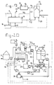
- the present invention also relates to an installation which is suitable for carrying out the method as described above, comprising:
- the installation (shown schematically in Figure 2) consists of the combination of a batch reactor (to which all influent (7) is added at once per cycle) or a fed batch reactor (to which the influent is added gradually or stepwise per cycle) as nitrification reactor (9) and a continuously fed upflow sludge bed (USB) reactor as denitrification reactor (13).
- the two reactors are operated connected in series, without bypass of the nitrification reactor (9) but optionally with backmixing (33) from the denitrification reactor (13) to the nitrification reactor (9).
- the nitrification reactor (9) of the installation is provided with aeration (10), a feed of liquid (7) to be treated, a sludge discharge (11) and optionally a feed of effluent from the denitrification reactor (33), all of which are controlled by the WAZU respiration meter (18) (Netherlands Patent Application 86.00396, filed on 6 February 1986). This respiration meter also controls the metering of the source of carbon (14) for the denitrification reactor (13).
- This denitrification reactor is additionally provided with nitrogen gas discharge (17) and effluent recirculation (33) or discharge (16).
- FIG. 4 Another embodiment of the installation according to the invention (shown schematically in Figure 4) is also provided with a line (32) through which the effluent from the denitrification reactor (13) can be partially recycled to the influent (12) for the denitrification reactor (13) and additionally this installation is provided with a feed of one or more acid-neutralizing chemicals (8) to the nitrification reactor (9).
- the installation can comprise a combination of the two above installations ( Figures 4 and 5), i.e. an installation as shown in Figure 6, this installation being provided with a line through which the effluent (32, 33) from the denitrification reactor (13) can be partially recycled (33 and 32 respectively) to the nitrification reactor (9) and to the influent (12) for the denitrification reactor (13).
- the three lastmentioned installations, shown in Figures 4, 5 and 6, can comprise a further addition (see Figure 7) in the form of a feed of chemicals for phosphate precipitation (20).
- the installations according to the invention which have already been described can be provided with the flocculation installations at various locations ( Figures 8, 9 and 10).
- the flocculation installation (19) is positioned in such a way that the effluent (16) from the denitrification reactor (13) flows through the flocculation installation (19 and Figure 3) upstream of the recycle (34, 35) or discharge (16).
- the flocculation installation (19) is positioned in such a way that only the effluent (16) from the denitrification reactor (13) which is to be discharged flows through the flocculation installation (19).
- the flocculation installation (19) is positioned in such a way that the effluent (12) originating from the nitrification reactor (9) flows through the flocculation installation (19) before it flows into the denitrification reactor (13).
- the installations according to the invention in which the nitrification reactor is provided with feed of the effluent (16, 33, 34) from the denitrification reactor (13) can be provided with a spray installation (25 and Figure 10) through which the effluent (16, 33, 34) from the denitrification reactor (13) can be sprayed into the nitrification reactor (9) to prevent foam formation.
- Fermented manure i.e. the liquid fraction obtained by centrifugation of anaerobic fermented floating pig manure
- Fermented manure is treated in the apparatus shown in fig.11 consisting of a nitrification reactor (9) having a usable volume of 50 m3, a separator (19) consisting of a pipe flocculator (27) and a centrifuge (28) and two denitrification reactors which are positioned parallel to each other each having a usable sludge bed volume of 10 m3.
- the nitrification reactor in this example is a fed batch reactor with a stepwise addition (0.2 m3 of manure per step) of fermented manure. A total of 2 m3 of manure is added in ten steps.
- a WAZU respiration meter (trademark RA-1000; marketed by Manotherm) is coupled to the nitrification reactor to monitor the actual respiration velocity. Further the oxygen concentration in the nitrification reactor is monitored with an oxygen sensor.
- Fig. 12 gives the oxygen concentration in the nitrification reactor as a function of the time. The average dose of the fermented manure in the present nitrification reactor was in this test about 10 m3 a day.
- the pH-value is also measured in the nitrification reactor. Lime milk is supplied when the pH-value is below 6.5.
- the temperature is also monitored and is kept at a value below 33°C by means of a heat exchanger.
- the concentration of nitrificible nitrogen in the fermented manure is 6000 mg N/l.
- the effluent of the nitrification reactor has a nitrate-N concentration of 1100 mg N/l and a phosphate-P concentration of 25 mg P/l.
- the nitrogen-N concentration is lower than could be expected on the basis of the dilution of the reactor contents with effluent of the denitrification reactor. This is the consequence of some denitrification in the nitrification reactor during the sedimentation period and the incorporation of nitrogen in the biomass.
- the effluent of the nitrification reactor is pumped through a pipe flocculator.
- a 41 w.% (weight/weight) solution of FeCl3 (ferrichloride, ironIIIchloride) is dosed in an amount of 2.5 l per m3 effluent of the nitrification reactor.
- lime milk and/or caustic soda is supplied until the pH-value has reached 5.8.
- polyelectrolite is dosed (76 mg per m3 effluent of the nitrification reactor).
- the liquid passes through a centrifuge separating in a sludge stream and a liquid stream.
- the nitrate-N and phosphate-P concentration in the effluent of the centrifuge amount 1100 mg N/l and ⁇ 0.5 mg P/l, respectively.
- the effluent of the centrifuge is then put through the two denitrification reactors that have been arranged parallel. Methanol is added on the basis of the nitrate concentration in the influent stream.
- the denitrification process is monitored by means of the gas production (1850 l/h).
- the pH-value of the denitrification reactors is between 9.0 and 9.3.
- the temperature is kept below 35°C by means of a heat exchanger.
- the effluent of the denitrification reactors is recirculated for 80% and discharged for 20%. Analysis shows a nitrate-N concentration ⁇ 10 mg N/l and a phosphate-P concentration of ⁇ 0.5 mg P/l.
- Table A shows the quality of the fermented manure before and after treatment in the present apparatus.
- Table B illustrates the quality of the effluent obtained.
Abstract
Description
- The present invention relates to a method for processing manure, fermented manure or waste water having a relatively high Kjeldahl-N concentration, said liquid manure being subjected to nitrification in a first step and to denitrification in a subsequent step, an aerated reactor which contains active sludge rich in nitrifying bacteria being used in the nitrification step and acid-neutralizing chemicals being added to said reactor if necessary and a continuously fed upflow sludge bed (USB) reactor which contains a very compact biomass which is capable of converting nitrate to nitrogen gas and to which an organic substrate is added being used in the denitrification step.
- A method of this type is known from, inter alia, Agrarisch Dagblad of 14 March 1988. With this method the liquid fraction of fermented semi-liquid manure is treated. The biologically degradable organic substances, nitrifiable nitrogen and phosphorus which are present in the liquid fraction of anaerobic or fermented semi-liquid manure can be largely removed. The method essentially consists in a coupling of a nitrification step in a nitrification reactor in which ammonia is converted by bacteria to oxidized nitrogen with a denitrification step in a denitrification reactor in which oxidized nitrogen is converted by bacteria to nitrogen gas, the phosphate present in the liquid being concentrated as a chemical precipitate in the reactor at the same time. Oxidation of ammonia results in lowering of the pH, which with this method can be countered by metering in lime and/or metering in effluent from the denitrification reactor (recycling) to the nitrification reactor. During the nitrification step of this method there will also be some removal of nitrogen and phosphate since the bacteria degrade biologically degradable substance which has passed through the fermentation to give CO₂ and H₂O. The nitrogen and phosphorus thus liberated can be incorporated in the new cells of the active sludge. With the method the nitrification reactor (which can be either a fed batch reactor or a batch reactor) is operated batchwise. It is then aerated until all ammonia has been nitrified, after which the aeration is stopped temporarily in order to allow the sludge to settle. The nitrified liquid manure is run off for treatment in the denitrification step, while the active sludge remains behind in the nitrification reactor for a subsequent cycle. In the denitrification step the effluent from the nitrification reactor is pumped upwards through a USB (upflow sludge bed) reactor. In this reactor there is a very compact biomass which is capable of converting nitrate to nitrogen gas. In order to allow this step to proceed, an organic substrate - for example methanol - must be added to the reactor. Acid is consumed during the denitrification step, as a result of which the pH in the bacterial bed rises. As a consequence of this rise, an insoluble precipitate of phosphate with the calcium ions present in the liquid forms. The manure processing consisting of manure fermentation and separation of fermented manure, followed by the method for treatment of the liquid fraction of fermented semi-liquid manure, which has been described above, is shown in Figure 1.
- A number of manure processing works are being developed at present, for example Promest in Helmond and Memon in Deventer. In these works semi-liquid manure is evaporated to give a dry product, which costs a great deal of energy since semi-liquid manure consists of more than 90% water. Moreover, this evaporation is a complex technology which in fact still has to be developed for use on manure. The cost price of processing of this type for the formation of dry granular or powder manure is consequently very high.
- An approach which differs from that described above is the treatment of semi-liquid manure in conventional effluent treatment installations. Currently this is also being used for treatment of liquid manure from calves. The conventional manure treatment has the significant disadvantages that the process produces a large amount of sludge (excess bacteria) and that the process is not capable of removing the phosphate. This means that extra provisions have to be made for sludge treatment and dephosphating. A conventional manure treatment also requires a fairly large amount of space.
- This method, as reported in Agrarisch Dagblad of 17 March 1988, has the advantage that it is relatively inexpensive and can be carried out in a compact installation. However, a number of problems also arise in this case in the treatment of fermented manure.
- A compact manure treatment installation for manure and fermented manure or Kjeldahl-N containing waste water can be produced and maintained only if:
- a) the metering of the fermented liquid fraction is matched to the nitrification capacity of the nitrification reactor. The nitrification reactor must not be overloaded but must also not operate underloaded.
- b) The metering of methanol (or other sources of carbon) to the denitrification reactor is matched to the nitrate load in the denitrification reactor. In the case of undermetering not all nitrate is removed; in the case of overmetering, however, methanol (or other source of carbon) is present in the effluent to be discharged.
- c) The effluent recycling from denitrification reactor to nitrification reactor is controlled such that it is optimal. Too little recycling leads to a nitrate concentration which has an inhibitory action on the bacteria; too much recycling has the consequence that the reactor is filled mainly with liquid which has already been treated.
- The aim of the present invention is to eliminate these problems. The present invention relates to a method of the type indicated in the preamble which is characterized in that the loading of the nitrification reactor is controlled to obtain an optimum nitrification and denitrification and this is obtained on the basis of the following data:
- the incoming nitrogen load (by controlling the fermented liquid manure);
- the incoming oxygen load (by controlling aeration);
- the information from the WAZU respiration meter or the information of an oxygen determination in the nitrification reactor;
- the concentration of oxidized nitrogen in the nitrification reactor, said concentration in the sludge/liquid mixture in the reactor being maintained between 0 and 4 gN/l by adjusting the ratio of the influent flow (the fermented liquid manure) and adjusting the recirculation flow and
- by maintaining the concentration of oxidized nitrogen in the influent for the denitrification reactor between 0 and 4 g N/l;
- maintaining the incoming oxidized nitrogen load, below or equal to the nitrate removal capacity so the nitrate concentration in the effluent is below the allowable nitrate effluent concentration, and controlling it by measuring the gas production in the denitrification reactor and/or the nitrate effluent concentration;
- and supplying an amount of organic substrate calculated from the incoming oxidized nitrogen load and/or the gas production in the denitrification reactor; the temperature in both the nitrification reactor and the denitrification reactor being kept below 40°C and the pH-value in the nitrification reactor being maintained in the range of 6 to 8.5.
- An important aspect of the invention is the possibility to use one instrument, a respiration meter (WAZU respiration meter), with which the time at which the treatment processes are complete is established and with which both Kjeldahl N concentration in the liquid fraction of fermented manure to be treated and the nitrate concentration of the effluent from the nitrification reactor (= feed for the denitrification reactor) can be calculated. The liquid streams and control lines in relation to the respiration meter are shown schematically in Figure 2. The respiration meter can control the entire method automatically on the basis of the data collated and calculated by the instrument.
- Another aspect of the invention is the use of separation step, e.g. a physical/chemical flocculation step and a floccule separator or a membrane technology before or after the denitrification step. Purpose of said separation previous to the denitrification reactor is catching suspended and colloïdally dissolved organic substances, that otherwise would mineralize in the denitrification reactor resulting in the formation of ammonium nitrogen. A physical/chemical flocculation step plus floccule separation is shown schematically in Figure 3. The residual organic substance can be removed from the effluent with the aid of flocculating auxiliaries and a process for separation of the flocculant from the effluent. By positioning upstream of the denitrification step, the organic substances can be removed before they are converted to inorganic substances and ammonium nitrogen is formed. A further advantage of this is that the carbonate content in the effluent from the nitrification reactor is low (lower than in the effluent from the denitrification reactor, to which organic substrate is added). This is advantageous if a flocculating auxiliary is used which forms a precipitate with carbonate, such as, for example, iron chloride. If a flocculating auxiliary is used which contains cations which precipitate with phosphate, an additional phosphate treatment takes place.
- Furthermore, the optimum conditions for the present treatment methods have been investigated in both the nitrification and the denitrification reactor. The biomass in both the nitrification reactor and the denitrification reactor produces heat. Because of the high concentration of biomass and the high rates of conversion which are realized in both reactors, there will be a net excess of heat in both reactors if no measures are taken. It is known, from observations made by the Applicant in laboratory experiments, that for a nitrifying bacterial population the optimum temperature of this bacterial population is between 31 and 35°C and that the maximum temperature which can be tolerated is 40°C. On the basis of general scientific information, it can be anticipated that the same temperature limits apply for the denitrifying bacterial population. Thermophilic denitrifying bacteria are known. These operate at temperatures above about 50°C. However. for various reasons it is not desirable to use thermophilic organisms in the denitrification reactor: the effluent to be discharged will be much too warm and the recycle stream to the nitrification reactor may not be too warm. Both the nitrification and the denitrification reactor can be operated only if there is provision for removal of heat from the respective reactor contents.
- For the present method, the conditions in the denitrification reactor must be kept such that phosphate can precipitate. The efficiency of the phosphate removal is dependent on the pH and the HCO₃⁻/CO₃²⁻ ratio in the denitrification reactor.
- The desired pH can be obtained by using an organic C source for the denitrification reactor with a specific chemical oxygen consumption (COC)/total organic carbon (TOC) ratio in the present method. The fact is that alkalinity (alkali, bicarbonate and carbonate) is produced in the denitrification reactor under the influence of the denitrification reaction. The production of alkalinity is dependent on the COC/TOC ratio of the organic C source in the denitrification reaction. Usually methanol is used as organic C source. Methanol has a high COC/TOC ratio and results in a higher production of alkalinity than, for example, glucose, which has a much lower COC/TOC ratio. Experiments have shown that the COC/TOC ratio must be 3.75 or or below.
- As stated, the PH-value falls in the nitrification reactor on the oxidation of the ammonia. To counter acidification of the reactor, an alkali can be metered in or effluent can be recycled from the denitrification reactor to the nitrification reactor. It has been established experimentally that the concentration of oxidized nitrogen in the nitrification reactor in the sludge/liquid mixture is between 0 and 4 g N/l and preferably is in the range limited by 0 and 1.5 g N/l. Furthermore, it has been found that the concentration of oxidized nitrogen in the influent for the denitrification reactor is between 0 and 4 g N/l and is preferably between 1.0 and 1.4 g N/l. In order to achieve this, the effluent from the denitrification reactor can be recycled. This recycling provides dilution of the concentration of oxidized nitrogen at the feed location in the reactor. Furthermore, this recycling is intended to obtain a higher stream velocity in the denitrification reactor, which promotes the contact between biomass and substrate in the reactor. Recycling can take place directly from effluent stream to influent stream for the denitrification reactor. It is, however, also possible (and in fact better for the overall process) for recycling of effluent from the denitrification reactor to be used, this recycling taking place entirely or partially via the nitrification reactor (see e.g. Figure 5). The aim of this is then to achieve both a saving in the chemicals consumption for pH control in the nitrification reactor and to achieve a dilution of the reactor contents of the nitrification reactor such that the content of oxidized nitrogen is always lower than 4 g N/l.
- The present invention also relates to an installation which is suitable for carrying out the method as described above, comprising:
- a nitrification reactor which is provided with an aeration, feed of liquid to be treated, feed of acid-neutralizing chemicals, active sludge rich in nitrifying bacteria, a sludge discharge, an effluent discharge;
- a line through which the effluent from the reactor can be fed to the denitrification reactor;
- a denitrification reactor which is provided with a feed of effluent from the denitrification reactor, feed of a carbon source, an upflow sludge bed (USB) column, a very compact biomass capable of converting nitrate to nitrogen gas, a discharge of phosphate-rich sludge, an effluent discharge, a nitrogen gas discharge;
- a line through which the effluent from the denitrification reactor can be discharged which is characterized in that the installation (shown schematically in Figure 2) is provided with one or more wazu respiration meters (18) controlling the aeration (10), the liquid supply to be treated (7), the sludge discharche (11) of the nitrification reactor and the supply of the source of carbon (14).
- In the most simple form, the installation (shown schematically in Figure 2) consists of the combination of a batch reactor (to which all influent (7) is added at once per cycle) or a fed batch reactor (to which the influent is added gradually or stepwise per cycle) as nitrification reactor (9) and a continuously fed upflow sludge bed (USB) reactor as denitrification reactor (13). The two reactors are operated connected in series, without bypass of the nitrification reactor (9) but optionally with backmixing (33) from the denitrification reactor (13) to the nitrification reactor (9).
- The use of the WAZU respiration meter (18) (Netherlands Patent Application 86.00396, filed on 6 February 1986 &. EP-A 257057), a measurement and control unit with which the course of the respiration rate of the biomass in the reactor (9) is followed, is characteristic of the installation according to the present invention.
- The nitrification reactor (9) of the installation is provided with aeration (10), a feed of liquid (7) to be treated, a sludge discharge (11) and optionally a feed of effluent from the denitrification reactor (33), all of which are controlled by the WAZU respiration meter (18) (Netherlands Patent Application 86.00396, filed on 6 February 1986). This respiration meter also controls the metering of the source of carbon (14) for the denitrification reactor (13). This denitrification reactor is additionally provided with nitrogen gas discharge (17) and effluent recirculation (33) or discharge (16).
- Another embodiment of the installation according to the invention (shown schematically in Figure 4) is also provided with a line (32) through which the effluent from the denitrification reactor (13) can be partially recycled to the influent (12) for the denitrification reactor (13) and additionally this installation is provided with a feed of one or more acid-neutralizing chemicals (8) to the nitrification reactor (9).
- Furthermore, the installation can comprise a combination of the two above installations (Figures 4 and 5), i.e. an installation as shown in Figure 6, this installation being provided with a line through which the effluent (32, 33) from the denitrification reactor (13) can be partially recycled (33 and 32 respectively) to the nitrification reactor (9) and to the influent (12) for the denitrification reactor (13).
- The three lastmentioned installations, shown in Figures 4, 5 and 6, can comprise a further addition (see Figure 7) in the form of a feed of chemicals for phosphate precipitation (20).
- Furthermore, all of these installations (shown in Figures 4, 5, 6 and 7) can be provided with one or more flocculation installations (19). The flocculation installation as such is shown schematically in Figure 3.
- The installations according to the invention which have already been described can be provided with the flocculation installations at various locations (Figures 8, 9 and 10). In the installation according to Figure 8, the flocculation installation (19) is positioned in such a way that the effluent (16) from the denitrification reactor (13) flows through the flocculation installation (19 and Figure 3) upstream of the recycle (34, 35) or discharge (16).
- In the installation according to Figure 9, the flocculation installation (19) is positioned in such a way that only the effluent (16) from the denitrification reactor (13) which is to be discharged flows through the flocculation installation (19).
- In the installation according to Figure 10, which is preferred, the flocculation installation (19) is positioned in such a way that the effluent (12) originating from the nitrification reactor (9) flows through the flocculation installation (19) before it flows into the denitrification reactor (13).
- The installations according to the invention in which the nitrification reactor is provided with feed of the effluent (16, 33, 34) from the denitrification reactor (13) can be provided with a spray installation (25 and Figure 10) through which the effluent (16, 33, 34) from the denitrification reactor (13) can be sprayed into the nitrification reactor (9) to prevent foam formation.
- Furthermore, all installations according to the invention can be provided with one or more buffer tanks (23 and Figure 10). The examples given serve to illustrate the invention and must not be regarded as restrictive.
- A possible embodiment of the present invention, not limiting the scope of the invention, is illustrated by means of the following example.
- Fermented manure (i.e. the liquid fraction obtained by centrifugation of anaerobic fermented floating pig manure) is treated in the apparatus shown in fig.11 consisting of a nitrification reactor (9) having a usable volume of 50 m³, a separator (19) consisting of a pipe flocculator (27) and a centrifuge (28) and two denitrification reactors which are positioned parallel to each other each having a usable sludge bed volume of 10 m³.
- The nitrification reactor in this example is a fed batch reactor with a stepwise addition (0.2 m³ of manure per step) of fermented manure. A total of 2 m³ of manure is added in ten steps.
- In the total cyclus of the
nitrification reactor 8 m³ of effluent of de denitrification reactor is supplied proporationally distributed in the time. After a total of 2 m³ fermented manure has been introduced in a nitrification reactor and all ammonium nitrogen has been nitrificated the aeration is ended and the active sludge is allowed to sediment during sixty minutes. After thesedimentation period 10 m³ of the supernatant liquid is discarded as an effluent of the nitrification reactor. Than a new cyclus is started wherein again 2 m³ of fermented manure and 8 m³ of effluent of the denitrification reactor are added. - A WAZU respiration meter (trademark RA-1000; marketed by Manotherm) is coupled to the nitrification reactor to monitor the actual respiration velocity. Further the oxygen concentration in the nitrification reactor is monitored with an oxygen sensor.
- After the addition of 0.2 m³ of fermented manure the actual respiration velocity increases and the oxygen concentration in the nitrification reactor decreases. When the ammonium hydrogen added with the fermented manure is nitrificated the actual respiration velocity decreases to the basis level and the oxygen concentration in the nitrification reactor increases. After falling underneath the set point for the respiration velocity and/or exceeding of the set point of the oxygen concentration another 0.2 m³ of fermented manure is added to the nitrifaction reactor. Fig. 12 gives the oxygen concentration in the nitrification reactor as a function of the time. The average dose of the fermented manure in the present nitrification reactor was in this test about 10 m³ a day.
- The pH-value is also measured in the nitrification reactor. Lime milk is supplied when the pH-value is below 6.5.
- The temperature is also monitored and is kept at a value below 33°C by means of a heat exchanger.
- From the oxygen consumption of the substrate during a cyclus (the cumulative actual respiration velocity minus the cumulative basis respiration velocity) it can be calculated that the concentration of nitrificible nitrogen in the fermented manure is 6000 mg N/l. The effluent of the nitrification reactor has a nitrate-N concentration of 1100 mg N/l and a phosphate-P concentration of 25 mg P/l. The nitrogen-N concentration is lower than could be expected on the basis of the dilution of the reactor contents with effluent of the denitrification reactor. This is the consequence of some denitrification in the nitrification reactor during the sedimentation period and the incorporation of nitrogen in the biomass.
- The effluent of the nitrification reactor is pumped through a pipe flocculator. At the beginning of this flocculator a 41 w.% (weight/weight) solution of FeCl₃ (ferrichloride, ironIIIchloride) is dosed in an amount of 2.5 l per m³ effluent of the nitrification reactor. In the middle of the pipe flocculator lime milk and/or caustic soda is supplied until the pH-value has reached 5.8. At the end of the pipe flocculator polyelectrolite is dosed (76 mg per m³ effluent of the nitrification reactor). The liquid than passes through a centrifuge separating in a sludge stream and a liquid stream. The nitrate-N and phosphate-P concentration in the effluent of the
centrifuge amount 1100 mg N/l and <0.5 mg P/l, respectively. - The effluent of the centrifuge is then put through the two denitrification reactors that have been arranged parallel. Methanol is added on the basis of the nitrate concentration in the influent stream. The denitrification process is monitored by means of the gas production (1850 l/h). The pH-value of the denitrification reactors is between 9.0 and 9.3. The temperature is kept below 35°C by means of a heat exchanger. The effluent of the denitrification reactors is recirculated for 80% and discharged for 20%. Analysis shows a nitrate-N concentration < 10 mg N/l and a phosphate-P concentration of < 0.5 mg P/l.
- Table A shows the quality of the fermented manure before and after treatment in the present apparatus.

- Table B illustrates the quality of the effluent obtained.

- Explanation of the numerals in the figures
- 1.
- Storage of semi-liquid manure
- 2.
- Fermentation installation
- 3.
- Biogas
- 4.
- Installation for energy generation
- 5.
- Installation for mechanical separation
- 6.
- Cake
- 7.
- Filtrate = liquid fraction to be treated
- 8.
- Holder for metering acid-neutralizing chemicals
- 9.
- Nitrification reactor
- 10.
- Air supply
- 11.
- Sludge discharge
- 12.
- Effluent from the nitrification reactor
- 13.
- Denitrification reactor
- 14.
- Holder for metering C source
- 15.
- Phosphate-rich sludge
- 16.
- Effluent from the denitrification reactor
- 17.
- Nitrogen gas
- 18.
- WAZU respiration meter
- 19.
- Separation installation
- 20.
- Holder for chemicals for phosphate precipitation
- 21.
- Sludge, flocculated material
- 22.
- Effluent originating from the flocculation installation, positioned downstream of the denitrification reactor
- 23.
- Buffer tank
- 24.
- Storage of discharged sludge
- 25.
- Spray installation
- 26.
- Influent pump
- 27.
- Static mixer and/or flocculating tank
- 28.
- Centrifuge
- 29.
- Sludge pump
- 30.
- Iron chloride storage
- 31.
- Metering pump
- 32.
- Effluent originating from the denitrification re-actor which recycles to the denitrification reactor
- 33.
- Effluent originating from the denitrification reactor which recycles to the nitrification reactor
- 34.
- Effluent originating from the separation step, which is positioned downstream of the denitrification reactor, which flows to the nitrification reactor
- 35.
- Effluent originating from the separation step, which is positioned downstream of the denitrification reactor, which recycles to the denitrification reactor
- 36.
- Effluent originating from the separation step, which is positioned upstream of the denitrification reactor.
- 37.
- Effluent from buffer tank (23).
Said points can be achieved by the use of separate instruments, it being necessary to carry out some of the diverse operations by hand. Moreover, the results of the various measurements cannot be integrated and translated into a control action without the intervention of one operator. Furthermore, the effluent from the nitrification reactor can still contain organic substances which cannot be further degraded in the nitrification reactor. Organic material which passes into the denitrification reactor can be converted into inorganic material in that reactor with the liberation of ammonium nitrogen which is then (insofar as it is not fed via the recycle stream ) discharged with the effluent.
in that the loading of the denitrification reactor is controlled to obtain an optimum denitrification;
Claims (29)
- Method for processing manure wherein fermented liquid manure is in a first step subjected to nitrification in an aerated reactor containing active sludge rich in nitrifying bacteria and optionally using acid-neutralizing chemicals that are added to said aerated reactor and in which method a second step comprises carrying out denitrification in a continuously fed upflow sludge bed (USB) reactor containing a very compact biomass for converting nitrate to nitrogen gas and by adding an organic substrate to said (USB) reactor, characterized in thata) the loading of the nitrification reactor is controlled to obtain optimal nitrification and denitrification the loading and this is obtained on the basis of the following data:- the incoming nitrogen load by controlling the fermented liquid manure;- the incoming oxygen load by controlling aeration;- the information from the WAZU respiration meter or the information of an oxygen determination in the nitrification reactor;- the concentration of oxidized nitrogen in the nitrification reactor, said concentration in the sludge/liquid mixture in the reactor being maintained between 0 and 4 g N/l by adjusting the ratio of the influent flow (the fermented liquid manure) and adjusting the recirculation flow andb) in that the loading of the denitrification reactor is controlled to obtain an optimal denitrification, said optimum being obtained by- maintaining the concentration of oxidized nitrogen in the influent for the denitrification reactor between 0 and 4 g N/l;- maintaining the incoming oxidized nitrogen load below or equal to the nitrate removal capacity so the nitrate concentration in the effluent is below the allowable concentration;- optionally monitoring the nitrate removal by measuring the gas production in the denitrification reactor and/or the nitrate effluent concentration;- supplying an amount of organic substrate preferably on the basis of the incoming oxidized nitrogen load and optionally on the basis of the gas production in the denitrification reactor and/or the nitrate effluent concentration;c) the temperature in both the nitrification reactor and the denitrification reactor being kept below 40°C;d) the pH-value in the nitrification reactor being maintained in the range limited by 6 and 8.5.
- Method according to Claim 1, characterized in that the effluent from the nitrification reactor is (first) passed through a physical/chemical flocculation installation.
- Method according to Claim 1 or 2, characterized in that liquid is recycled from the denitrification reactor to the nitrification reactor.
- Method according to Claim 2 or 3, characterized in that the flocculating substance contains cations capable of forming a precipitate with phosphate.
- Method according to Claim 4, characterized in that said flocculating substance is iron chloride.
- Method according to Claim 2 or 3, characterized in that the recycled liquid is passed through a spray installation before the liquid reaches the nitrification reactor.
- Method according to Claim 2 or 3, characterized in that part of the effluent after denitrification is also recycled to the effluent from the nitrification reactor before this flows into the denitrification reactor.
- Method according to one of the preceding claims, characterized in that the nitrification reactor is a batch reactor or a fed batch reactor having a continuous or batchwise addition of influent.
- Method according to one of the preceding claims, characterized in that chemicals for phosphate precipitation are added to the denitrification reactor.
- Method according to Claim 9, characterized in that Ca++, Fe+++, Mg++ and/or Al+++ are used.
- Method according to one of the preceding claims, characterized in that methanol is added as organic substrate to the denitrification reactor.
- Method according to one of the preceding claims, characterized in that glycol is added as organic substrate to the denitrification reactor.
- Method according to one of the preceding claims, characterized in that one or more acid-neutralizing chemicals are added to the nitrification reactor.
- Method according to claim 13, characterized in that lime is added.
- Method according to one of the preceding claims, characterized in that the pH in the nitrification reactor is maintained at 7-8.
- Method according to one of the preceding claims, characterized in that the temperature in both the nitrification reactor and in the denitrification reactor is maintained at 31-35°C.
- Method according to one of the preceding claims, characterized in that the concentration of oxidized nitrogen in the influent for the denitrification reactor is maintained at 1.0-1.4 g N/l.
- Method according to one of the preceding claims, characterized in that the concentration of oxidized nitrogen in the nitrification reactor is maintained at 0-1.5 g N/l.
- Installation suitable for carrying out the method according to one of the preceding claims, comprising:- a nitrification reactor (9), which is provided with an aeration (10), a feed of liquid (7) to be treated, a feed of acid-neutralizing chemicals (8), active sludge rich in nitrifying bacteria (9), a sludge discharge (11), an effluent discharge (12);- a line through which the effluent (12) from the nitrification reactor (9) can be fed to the denitrification reactor (13);- a denitrification reactor (13), which is provided with feed of effluent (12) from the nitrification reactor (9), a feed of a carbon source (14), an upflow sludge bed (USB) column (13), a very compact biomass (13) capable of converting nitrate to nitrogen gas, a discharge (15) of phosphate-rich sludge, an effluent discharge (16), a nitrogen gas discharge (17);- a line through which the effluent (16) from the denitrification reactor (13) can be discharged,characterized in that the installation (shown schematically in Figure 2) is provided with one or more WAZU respiration meters (18) controlling the aeration (10), the supply of liquid to be treated (7), the sludge discharge (11) of the nitrification reactor (9) and the supply of the source of carbon (14).
- Installation according to Claim 19, characterized in that this is provided with a line (32) through which the effluent from the denitrification reactor (13) can be partially recycled to the influent (12) for the denitrification reactor (13).
- Installation according to Claim 19, characterized in that this is provided with a line (33) through which the effluent from the denitrification reactor (13) can be partially recycled to the nitrification reactor (9).
- Installation according to Claim 19, characterized in that this is provided with a line through which the effluent (32,33) from the denitrification reactor (13) can be partially recycled to the nitrification reactor (9) and to the effluent for the denitrification reactor (13).
- Installation according to one of Claims 19-22, characterized in that this is provided with a feed of chemicals for phosphate precipitation (20).
- Installation according to one of Claims 19-22, characterized in that this comprises one or more flocculation installations (19) (and shown schematically in Figure 3).
- Installation according to Claim 24, characterized in that the flocculation installation (19) is positioned in such a way (shown schematically in Figure 8) that the effluent (16) from the denitrification reactor (13) flows through the flocculation installation (19) before recycling (34,35) or discharge (16).
- Installation according to Claim 24, characterized in that the flocculation installation (19) is positioned in such a way that only the effluent (16) from the denitrification reactor (13) which is to be discharged flows through the flocculation installation (19).
- Installation according to Claim 24, characterized in that the flocculation installation (19) is positioned in such a way that the effluent (12) originating from the nitrification reactor (9) flows through the flocculation installation (19) before flowing into the denitrification reactor (13).
- Installation according to one of the preceding claims, characterized in that this is provided with a spray installation (25) through which the effluent (16, 33, 34) from the denitrification reactor (13) can be sprayed into the nitrification reactor (9).
- Installation according to one of the preceding claims, characterized in that this is provided with buffer tanks (23).
Priority Applications (1)
| Application Number | Priority Date | Filing Date | Title |
|---|---|---|---|
| AT90202728T ATE99651T1 (en) | 1989-10-17 | 1990-10-12 | PROCESS AND PLANT FOR TREATMENT OF MANURE, FERMENTED MANURE AND WASTEWATER CONTAINING KJELDAHL NITROGEN. |
Applications Claiming Priority (2)
| Application Number | Priority Date | Filing Date | Title |
|---|---|---|---|
| NL8902573 | 1989-10-17 | ||
| NL8902573A NL8902573A (en) | 1989-10-17 | 1989-10-17 | METHOD AND APPARATUS FOR PROCESSING MANURE |
Publications (2)
| Publication Number | Publication Date |
|---|---|
| EP0423889A1 EP0423889A1 (en) | 1991-04-24 |
| EP0423889B1 true EP0423889B1 (en) | 1994-01-05 |
Family
ID=19855470
Family Applications (1)
| Application Number | Title | Priority Date | Filing Date |
|---|---|---|---|
| EP19900202728 Expired - Lifetime EP0423889B1 (en) | 1989-10-17 | 1990-10-12 | Method and installation for processing manure, fermented manure and Kjeldahl-N containing waste water |
Country Status (20)
| Country | Link |
|---|---|
| US (2) | US5232583A (en) |
| EP (1) | EP0423889B1 (en) |
| JP (1) | JPH03146197A (en) |
| KR (1) | KR910007840A (en) |
| AT (1) | ATE99651T1 (en) |
| CA (1) | CA2027787A1 (en) |
| CS (1) | CS501790A3 (en) |
| DE (1) | DE69005780T2 (en) |
| DK (1) | DK0423889T3 (en) |
| ES (1) | ES2049914T3 (en) |
| FI (1) | FI905115A0 (en) |
| HR (1) | HRP920380A2 (en) |
| HU (1) | HUT61254A (en) |
| IL (1) | IL96034A (en) |
| NL (1) | NL8902573A (en) |
| NO (1) | NO904490L (en) |
| PL (1) | PL287363A1 (en) |
| RO (1) | RO109323B1 (en) |
| YU (1) | YU46972B (en) |
| ZA (1) | ZA908299B (en) |
Families Citing this family (31)
| Publication number | Priority date | Publication date | Assignee | Title |
|---|---|---|---|---|
| EP0509152A1 (en) * | 1991-04-17 | 1992-10-21 | Ecotechniek B.V. | Method and apparatus for processing manure |
| GB2259699B (en) * | 1991-09-21 | 1994-04-06 | Osc Process Engineering Limite | Process and plant for the treatment of high-strength ammoniacal liquors |
| NL9200845A (en) * | 1992-05-13 | 1993-12-01 | Epenhuysen Chem Fab | FERTILIZER SOLUTION, METHOD FOR PREPARING THIS FERTILIZER SOLUTION AND USE THEREOF |
| EP0592058A1 (en) * | 1992-10-05 | 1994-04-13 | MANNESMANN Aktiengesellschaft | Process for optimising nitrogen removal in clarification processes |
| US5558763A (en) * | 1993-06-24 | 1996-09-24 | Hitachi Plant Engineering & Construction Co., Ltd. | Sewage treatment system with air jetting means |
| FR2707621B1 (en) * | 1993-07-12 | 1995-10-20 | Omnium Traitement Valorisa | Process and installation for purifying water with denitrifying physico-chemical sludge. |
| KR960009385B1 (en) * | 1993-11-24 | 1996-07-18 | Samsung Bp Chemicals Co Ltd | Apparatus and method for wastewater treatment by activated sludge process type |
| EP0828692B1 (en) * | 1995-05-11 | 1998-12-16 | BioBalance A/S | Novel method for the control of biodegradation |
| US5876603A (en) * | 1995-08-10 | 1999-03-02 | Hitachi Plant Engineering & Construction Co., Ltd. | Method of biologically removing nitrogen and system therefor |
| US5885461A (en) * | 1997-02-07 | 1999-03-23 | Purin-Pur, Inc. | Process and system for treatment of pig and swine manure for environmental enhancement |
| BE1011909A7 (en) * | 1998-05-15 | 2000-02-01 | Polymetal Nv | REST OF CHARGE dung processing system. |
| KR20000066396A (en) * | 1999-04-16 | 2000-11-15 | 정명식 | Process and Equipments for the Treatment of Industrial Wastewater Containing Concentrated Nitrogen |
| EP1595551B1 (en) | 2000-08-22 | 2009-11-18 | GFE Patent A/S | Concept for slurry separation and biogas production. |
| US7585413B2 (en) * | 2001-02-20 | 2009-09-08 | Hoffland Robert O | Method and apparatus for treating animal waste and wastewater |
| KR100378569B1 (en) * | 2001-12-20 | 2003-04-08 | 이익만 | auto-heated and mesophilic denitrification system for wastewater sludge |
| US6692642B2 (en) * | 2002-04-30 | 2004-02-17 | International Waste Management Systems | Organic slurry treatment process |
| MY143253A (en) * | 2002-08-01 | 2011-04-15 | Gfe Patent As | Method and device for stripping ammonia from liquids |
| US7763176B2 (en) * | 2002-11-29 | 2010-07-27 | Lucie Valée, legal representative | Process for the treatment of pig manure and the use thereof |
| GB0308366D0 (en) * | 2003-04-11 | 2003-05-14 | Enviro Control Ltd | Apparatus for and a method of treating organic waste |
| JP4688059B2 (en) * | 2004-10-29 | 2011-05-25 | 株式会社日立プラントテクノロジー | Anaerobic ammonia oxidation apparatus and operation method thereof |
| ES2552002T3 (en) * | 2005-10-26 | 2015-11-25 | Daniel Blanchette | Water purification method, process and apparatus |
| US7569148B2 (en) * | 2006-08-23 | 2009-08-04 | Siemens Water Technologies Corp. | Continuous membrane filtration and solids reduction |
| US20080053913A1 (en) * | 2006-09-06 | 2008-03-06 | Fassbender Alexander G | Nutrient recovery process |
| US20080053909A1 (en) * | 2006-09-06 | 2008-03-06 | Fassbender Alexander G | Ammonia recovery process |
| US20080156726A1 (en) * | 2006-09-06 | 2008-07-03 | Fassbender Alexander G | Integrating recycle stream ammonia treatment with biological nutrient removal |
| BE1017279A3 (en) * | 2006-10-17 | 2008-05-06 | Trevi Nv | Process for the fermentation of energetic and nutrient substances. |
| CN1948190B (en) * | 2006-11-07 | 2012-07-25 | 南京大学 | Treatment method of waste water in fluorofen production |
| US20100199514A1 (en) * | 2009-02-10 | 2010-08-12 | Vermont Organics Reclamation Inc. | Optimized apparatus and method for manure management |
| US20100200426A1 (en) * | 2009-02-10 | 2010-08-12 | Vermont Organics Reclamation Inc | Apparatus and method for phase separation of liquids and solids |
| CN108483655B (en) * | 2018-05-31 | 2021-07-30 | 中山大学 | Method for deep denitrification by coupling shortcut nitrification and denitrification with anaerobic ammonia oxidation and sulfur autotrophic denitrification |
| DE102018119088A1 (en) | 2018-08-06 | 2020-02-06 | Aev Energy Gmbh | Process for reducing the nutrient content of manure and poultry droppings |
Family Cites Families (16)
| Publication number | Priority date | Publication date | Assignee | Title |
|---|---|---|---|---|
| US4160724A (en) * | 1976-11-12 | 1979-07-10 | Ontario Research Foundation | Waste water treatment |
| NL7705427A (en) * | 1977-05-17 | 1978-11-21 | Stamicarbon | METHOD AND INSTALLATION FOR THE BIOLOGICAL PURIFICATION OF WASTE WATER. |
| JPS5653795A (en) * | 1979-10-09 | 1981-05-13 | Ebara Infilco Co Ltd | Controlling method for quantity of organic carbon source to be poured in biological denitriding |
| NL8006094A (en) * | 1980-11-07 | 1982-06-01 | Landbouw Hogeschool | METHOD FOR PURIFYING WASTE WATER AND / OR WASTE WATER SLUDGE. |
| JPS57204294A (en) * | 1981-06-10 | 1982-12-14 | Kubota Ltd | Denitrification of water |
| JPS5898195A (en) * | 1981-12-04 | 1983-06-10 | Hitachi Ltd | Controlling method for biological denitrifying process |
| NL8600396A (en) * | 1986-02-17 | 1987-09-16 | Rijkslandbouwhogeschool | METHOD FOR DETERMINING THE RESPIRATION RATE OF A RESPIRATORY MATERIAL IN A CONTINUOUS PROCESS FLOW AND AN APPARATUS SUITABLE FOR SUCH APPLICATION. |
| DE3605962A1 (en) * | 1986-02-25 | 1987-08-27 | Stadtwerke Viersen Gmbh | Process for nitrate depletion in the treatment of drinking water and apparatuses for carrying out the process |
| JPH0665399B2 (en) * | 1986-09-09 | 1994-08-24 | 株式会社西原環境衛生研究所 | Method and apparatus for treating activated sludge by intermittent aeration method |
| JPS63302996A (en) * | 1987-06-04 | 1988-12-09 | Ebara Infilco Co Ltd | Treatment of organic sewage |
| NZ227832A (en) * | 1988-02-05 | 1991-05-28 | Gist Brocades Nv | Industrial biological denitrification using ammonium ion as electron donor; inoculation material |
| US4818407A (en) * | 1988-03-24 | 1989-04-04 | Bogusch Eugene D | Nitrification with ammonia enrichment |
| FR2667057B1 (en) * | 1990-09-25 | 1993-07-09 | Degremont | IMPROVED REACTOR FOR THE BIOLOGICAL TREATMENT OF WASTEWATER. |
| US5213681A (en) * | 1991-09-09 | 1993-05-25 | T. Kruger, Inc. | Method for biologically removing nitrogen from wastewater |
| DE4133805C2 (en) * | 1991-10-12 | 1995-03-23 | Schreiber Berthold | Processes for biological wastewater treatment |
| US5182021A (en) * | 1991-12-16 | 1993-01-26 | Lehigh University | Biological process for enhanced removal of ammonia, nitrite, nitrate, and phosphate from wastewater |
-
1989
- 1989-10-17 NL NL8902573A patent/NL8902573A/en not_active Application Discontinuation
-
1990
- 1990-10-12 DE DE1990605780 patent/DE69005780T2/en not_active Expired - Fee Related
- 1990-10-12 EP EP19900202728 patent/EP0423889B1/en not_active Expired - Lifetime
- 1990-10-12 DK DK90202728T patent/DK0423889T3/en active
- 1990-10-12 ES ES90202728T patent/ES2049914T3/en not_active Expired - Lifetime
- 1990-10-12 AT AT90202728T patent/ATE99651T1/en not_active IP Right Cessation
- 1990-10-16 RO RO146132A patent/RO109323B1/en unknown
- 1990-10-16 KR KR1019900016411A patent/KR910007840A/en not_active Application Discontinuation
- 1990-10-16 CA CA 2027787 patent/CA2027787A1/en not_active Abandoned
- 1990-10-16 CS CS905017A patent/CS501790A3/en unknown
- 1990-10-16 IL IL9603490A patent/IL96034A/en not_active IP Right Cessation
- 1990-10-17 YU YU195890A patent/YU46972B/en unknown
- 1990-10-17 NO NO90904490A patent/NO904490L/en unknown
- 1990-10-17 HU HU906478A patent/HUT61254A/en unknown
- 1990-10-17 FI FI905115A patent/FI905115A0/en not_active IP Right Cessation
- 1990-10-17 ZA ZA908299A patent/ZA908299B/en unknown
- 1990-10-17 PL PL28736390A patent/PL287363A1/en unknown
- 1990-10-17 US US07/599,345 patent/US5232583A/en not_active Expired - Fee Related
- 1990-10-17 JP JP2280561A patent/JPH03146197A/en active Pending
-
1992
- 1992-09-21 HR HRP920380AA patent/HRP920380A2/en not_active Application Discontinuation
-
1993
- 1993-06-01 US US08/070,112 patent/US5296147A/en not_active Expired - Fee Related
Also Published As
| Publication number | Publication date |
|---|---|
| DK0423889T3 (en) | 1994-04-25 |
| US5296147A (en) | 1994-03-22 |
| NO904490L (en) | 1991-04-18 |
| EP0423889A1 (en) | 1991-04-24 |
| NO904490D0 (en) | 1990-10-17 |
| DE69005780D1 (en) | 1994-02-17 |
| IL96034A (en) | 1994-11-11 |
| YU46972B (en) | 1994-09-09 |
| IL96034A0 (en) | 1991-07-18 |
| DE69005780T2 (en) | 1994-04-28 |
| ZA908299B (en) | 1991-08-28 |
| RO109323B1 (en) | 1995-01-30 |
| HU906478D0 (en) | 1991-04-29 |
| FI905115A0 (en) | 1990-10-17 |
| CS501790A3 (en) | 1992-03-18 |
| ATE99651T1 (en) | 1994-01-15 |
| ES2049914T3 (en) | 1994-05-01 |
| HRP920380A2 (en) | 1994-04-30 |
| PL287363A1 (en) | 1991-06-03 |
| KR910007840A (en) | 1991-05-30 |
| US5232583A (en) | 1993-08-03 |
| JPH03146197A (en) | 1991-06-21 |
| CA2027787A1 (en) | 1991-04-18 |
| NL8902573A (en) | 1991-05-16 |
| YU195890A (en) | 1992-07-20 |
| HUT61254A (en) | 1992-12-28 |
Similar Documents
| Publication | Publication Date | Title |
|---|---|---|
| EP0423889B1 (en) | Method and installation for processing manure, fermented manure and Kjeldahl-N containing waste water | |
| EP0509609B1 (en) | Method and apparatus for processing manure | |
| Zhang et al. | 33 ANAEROBIC TREATMENT OF SWINE WASTE BY THE ANAEROBIC SEQUENCING BATCH REACTOR | |
| US7722768B2 (en) | Process for the simultaneous removal of BOD and phosphate from waste water | |
| US6616844B2 (en) | Method for treating high-concentrated organic wastewater using bio-maker | |
| US5076928A (en) | Process for biological wastewater treatment | |
| Pitman | Management of biological nutrient removal plant sludges—change the paradigms? | |
| CA1128460A (en) | Heavy metal removal from wastewater sludge | |
| US5543051A (en) | Biological phosphorus removal from waste water | |
| JPS5839599B2 (en) | Phosphorus removal method from organic waste liquid | |
| WO1996029290A1 (en) | Apparatus and treatment for wastewater | |
| US6982036B2 (en) | Chemically enhanced primary sludge fermentation method | |
| Ketchum Jr et al. | A comparison of biological and chemical phosphorus removals in continuous and sequencing batch reactors | |
| WO1995024361A1 (en) | Method of operating a sequencing batch reactor | |
| Ip et al. | Effect of alternating aerobic and anaerobic conditions on the economics of the activated sludge system | |
| Bishop et al. | Fate of nutrients during aerobic digestion | |
| JPH08141592A (en) | Anaerobic treatment method | |
| EP0710626A2 (en) | Process for reducing nitrogen content in waste waters | |
| Rabinowitz | The role of specific substrates in excess biological phosphorus removal | |
| WO1986003734A1 (en) | Nitrification/denitrification of waste material | |
| CN217398562U (en) | High-concentration nitrogen-containing wastewater treatment system | |
| Shepherd et al. | Development of a bench-scale air sparged continuous flow reactor for struvite precipitation from two different liquid swine manure storage systems | |
| CA1057867A (en) | Process for total sewage treatment | |
| KR200267684Y1 (en) | System for wastewater treatment using struvite(MAP) | |
| AU665138B2 (en) | Biological phosphorus removal from waste water |
Legal Events
| Date | Code | Title | Description |
|---|---|---|---|
| PUAI | Public reference made under article 153(3) epc to a published international application that has entered the european phase |
Free format text: ORIGINAL CODE: 0009012 |
|
| AK | Designated contracting states |
Kind code of ref document: A1 Designated state(s): AT BE CH DE DK ES FR GB GR IT LI LU NL SE |
|
| 17P | Request for examination filed |
Effective date: 19910813 |
|
| 17Q | First examination report despatched |
Effective date: 19920312 |
|
| ITF | It: translation for a ep patent filed |
Owner name: DE DOMINICIS & MAYER S. |
|
| GRAA | (expected) grant |
Free format text: ORIGINAL CODE: 0009210 |
|
| AK | Designated contracting states |
Kind code of ref document: B1 Designated state(s): AT BE CH DE DK ES FR GB GR IT LI LU NL SE |
|
| REF | Corresponds to: |
Ref document number: 99651 Country of ref document: AT Date of ref document: 19940115 Kind code of ref document: T |
|
| REF | Corresponds to: |
Ref document number: 69005780 Country of ref document: DE Date of ref document: 19940217 |
|
| REG | Reference to a national code |
Ref country code: GR Ref legal event code: FG4A Free format text: 3010394 |
|
| ET | Fr: translation filed | ||
| REG | Reference to a national code |
Ref country code: DK Ref legal event code: T3 |
|
| REG | Reference to a national code |
Ref country code: ES Ref legal event code: FG2A Ref document number: 2049914 Country of ref document: ES Kind code of ref document: T3 |
|
| PGFP | Annual fee paid to national office [announced via postgrant information from national office to epo] |
Ref country code: GR Payment date: 19940921 Year of fee payment: 5 |
|
| PGFP | Annual fee paid to national office [announced via postgrant information from national office to epo] |
Ref country code: GB Payment date: 19940929 Year of fee payment: 5 |
|
| PGFP | Annual fee paid to national office [announced via postgrant information from national office to epo] |
Ref country code: LU Payment date: 19941001 Year of fee payment: 5 |
|
| PGFP | Annual fee paid to national office [announced via postgrant information from national office to epo] |
Ref country code: FR Payment date: 19941007 Year of fee payment: 5 |
|
| PGFP | Annual fee paid to national office [announced via postgrant information from national office to epo] |
Ref country code: SE Payment date: 19941011 Year of fee payment: 5 Ref country code: DK Payment date: 19941011 Year of fee payment: 5 Ref country code: BE Payment date: 19941011 Year of fee payment: 5 Ref country code: AT Payment date: 19941011 Year of fee payment: 5 |
|
| PGFP | Annual fee paid to national office [announced via postgrant information from national office to epo] |
Ref country code: NL Payment date: 19941031 Year of fee payment: 5 |
|
| PGFP | Annual fee paid to national office [announced via postgrant information from national office to epo] |
Ref country code: DE Payment date: 19941104 Year of fee payment: 5 |
|
| PLBE | No opposition filed within time limit |
Free format text: ORIGINAL CODE: 0009261 |
|
| STAA | Information on the status of an ep patent application or granted ep patent |
Free format text: STATUS: NO OPPOSITION FILED WITHIN TIME LIMIT |
|
| PGFP | Annual fee paid to national office [announced via postgrant information from national office to epo] |
Ref country code: CH Payment date: 19941109 Year of fee payment: 5 |
|
| 26N | No opposition filed | ||
| EAL | Se: european patent in force in sweden |
Ref document number: 90202728.3 |
|
| PGFP | Annual fee paid to national office [announced via postgrant information from national office to epo] |
Ref country code: ES Payment date: 19950426 Year of fee payment: 5 |
|
| PG25 | Lapsed in a contracting state [announced via postgrant information from national office to epo] |
Ref country code: LU Free format text: LAPSE BECAUSE OF NON-PAYMENT OF DUE FEES Effective date: 19951012 Ref country code: GB Effective date: 19951012 Ref country code: DK Effective date: 19951012 Ref country code: AT Effective date: 19951012 |
|
| REG | Reference to a national code |
Ref country code: DK Ref legal event code: EBP |
|
| PG25 | Lapsed in a contracting state [announced via postgrant information from national office to epo] |
Ref country code: SE Effective date: 19951013 Ref country code: ES Free format text: LAPSE BECAUSE OF THE APPLICANT RENOUNCES Effective date: 19951013 |
|
| PG25 | Lapsed in a contracting state [announced via postgrant information from national office to epo] |
Ref country code: LI Effective date: 19951031 Ref country code: CH Effective date: 19951031 Ref country code: BE Effective date: 19951031 |
|
| BERE | Be: lapsed |
Owner name: ECOTECHNIEK B.V. Effective date: 19951031 |
|
| PG25 | Lapsed in a contracting state [announced via postgrant information from national office to epo] |
Ref country code: GR Free format text: THE PATENT HAS BEEN ANNULLED BY A DECISION OF A NATIONAL AUTHORITY Effective date: 19960430 |
|
| PG25 | Lapsed in a contracting state [announced via postgrant information from national office to epo] |
Ref country code: NL Effective date: 19960501 |
|
| GBPC | Gb: european patent ceased through non-payment of renewal fee |
Effective date: 19951012 |
|
| REG | Reference to a national code |
Ref country code: CH Ref legal event code: PL |
|
| PG25 | Lapsed in a contracting state [announced via postgrant information from national office to epo] |
Ref country code: FR Effective date: 19960628 |
|
| REG | Reference to a national code |
Ref country code: GR Ref legal event code: MM2A Free format text: 3010394 |
|
| EUG | Se: european patent has lapsed |
Ref document number: 90202728.3 |
|
| PG25 | Lapsed in a contracting state [announced via postgrant information from national office to epo] |
Ref country code: DE Effective date: 19960702 |
|
| NLV4 | Nl: lapsed or anulled due to non-payment of the annual fee |
Effective date: 19960501 |
|
| REG | Reference to a national code |
Ref country code: FR Ref legal event code: ST |
|
| REG | Reference to a national code |
Ref country code: ES Ref legal event code: FD2A Effective date: 19991007 |
|
| PG25 | Lapsed in a contracting state [announced via postgrant information from national office to epo] |
Ref country code: IT Free format text: LAPSE BECAUSE OF NON-PAYMENT OF DUE FEES;WARNING: LAPSES OF ITALIAN PATENTS WITH EFFECTIVE DATE BEFORE 2007 MAY HAVE OCCURRED AT ANY TIME BEFORE 2007. THE CORRECT EFFECTIVE DATE MAY BE DIFFERENT FROM THE ONE RECORDED. Effective date: 20051012 |