EP0423354B2 - Oxide superconductor wire, method of producing the same and article produced therefrom - Google Patents
Oxide superconductor wire, method of producing the same and article produced therefrom Download PDFInfo
- Publication number
- EP0423354B2 EP0423354B2 EP90905634A EP90905634A EP0423354B2 EP 0423354 B2 EP0423354 B2 EP 0423354B2 EP 90905634 A EP90905634 A EP 90905634A EP 90905634 A EP90905634 A EP 90905634A EP 0423354 B2 EP0423354 B2 EP 0423354B2
- Authority
- EP
- European Patent Office
- Prior art keywords
- oxide superconductive
- wire
- base
- layer
- oxide
- Prior art date
- Legal status (The legal status is an assumption and is not a legal conclusion. Google has not performed a legal analysis and makes no representation as to the accuracy of the status listed.)
- Expired - Lifetime
Links
- 238000000034 method Methods 0.000 title claims description 13
- 239000002887 superconductor Substances 0.000 title description 13
- 238000010438 heat treatment Methods 0.000 claims description 12
- 238000001816 cooling Methods 0.000 claims description 4
- 238000004519 manufacturing process Methods 0.000 claims description 4
- 230000000704 physical effect Effects 0.000 claims description 2
- 239000010410 layer Substances 0.000 description 50
- 239000000463 material Substances 0.000 description 15
- IJGRMHOSHXDMSA-UHFFFAOYSA-N Atomic nitrogen Chemical compound N#N IJGRMHOSHXDMSA-UHFFFAOYSA-N 0.000 description 6
- 239000010949 copper Substances 0.000 description 5
- 239000010408 film Substances 0.000 description 5
- RYGMFSIKBFXOCR-UHFFFAOYSA-N Copper Chemical compound [Cu] RYGMFSIKBFXOCR-UHFFFAOYSA-N 0.000 description 4
- 239000007789 gas Substances 0.000 description 4
- 238000004804 winding Methods 0.000 description 4
- 229910000838 Al alloy Inorganic materials 0.000 description 3
- 229910002480 Cu-O Inorganic materials 0.000 description 3
- 230000015556 catabolic process Effects 0.000 description 3
- 229910052802 copper Inorganic materials 0.000 description 3
- 238000006731 degradation reaction Methods 0.000 description 3
- 239000007788 liquid Substances 0.000 description 3
- 229910052757 nitrogen Inorganic materials 0.000 description 3
- 239000004332 silver Substances 0.000 description 3
- 229910000881 Cu alloy Inorganic materials 0.000 description 2
- BQCADISMDOOEFD-UHFFFAOYSA-N Silver Chemical compound [Ag] BQCADISMDOOEFD-UHFFFAOYSA-N 0.000 description 2
- ATJFFYVFTNAWJD-UHFFFAOYSA-N Tin Chemical compound [Sn] ATJFFYVFTNAWJD-UHFFFAOYSA-N 0.000 description 2
- 229910009203 Y-Ba-Cu-O Inorganic materials 0.000 description 2
- HCHKCACWOHOZIP-UHFFFAOYSA-N Zinc Chemical compound [Zn] HCHKCACWOHOZIP-UHFFFAOYSA-N 0.000 description 2
- 229910052782 aluminium Inorganic materials 0.000 description 2
- XAGFODPZIPBFFR-UHFFFAOYSA-N aluminium Chemical compound [Al] XAGFODPZIPBFFR-UHFFFAOYSA-N 0.000 description 2
- 238000005452 bending Methods 0.000 description 2
- 239000002131 composite material Substances 0.000 description 2
- 230000008602 contraction Effects 0.000 description 2
- 238000000151 deposition Methods 0.000 description 2
- 230000008021 deposition Effects 0.000 description 2
- APFVFJFRJDLVQX-UHFFFAOYSA-N indium atom Chemical compound [In] APFVFJFRJDLVQX-UHFFFAOYSA-N 0.000 description 2
- 238000011835 investigation Methods 0.000 description 2
- 229910052751 metal Inorganic materials 0.000 description 2
- 239000002184 metal Substances 0.000 description 2
- BASFCYQUMIYNBI-UHFFFAOYSA-N platinum Chemical compound [Pt] BASFCYQUMIYNBI-UHFFFAOYSA-N 0.000 description 2
- 239000011241 protective layer Substances 0.000 description 2
- 229910052709 silver Inorganic materials 0.000 description 2
- 230000000087 stabilizing effect Effects 0.000 description 2
- 239000000758 substrate Substances 0.000 description 2
- 229910001233 yttria-stabilized zirconia Inorganic materials 0.000 description 2
- 229910052725 zinc Inorganic materials 0.000 description 2
- 239000011701 zinc Substances 0.000 description 2
- 229910001316 Ag alloy Inorganic materials 0.000 description 1
- 229910015901 Bi-Sr-Ca-Cu-O Inorganic materials 0.000 description 1
- 229910000846 In alloy Inorganic materials 0.000 description 1
- 238000005481 NMR spectroscopy Methods 0.000 description 1
- 229910000978 Pb alloy Inorganic materials 0.000 description 1
- 229910001128 Sn alloy Inorganic materials 0.000 description 1
- PNEYBMLMFCGWSK-UHFFFAOYSA-N aluminium oxide Inorganic materials [O-2].[O-2].[O-2].[Al+3].[Al+3] PNEYBMLMFCGWSK-UHFFFAOYSA-N 0.000 description 1
- 230000005540 biological transmission Effects 0.000 description 1
- 230000015572 biosynthetic process Effects 0.000 description 1
- 239000000919 ceramic Substances 0.000 description 1
- 150000001875 compounds Chemical class 0.000 description 1
- 230000006835 compression Effects 0.000 description 1
- 238000007906 compression Methods 0.000 description 1
- 230000000593 degrading effect Effects 0.000 description 1
- 210000003298 dental enamel Anatomy 0.000 description 1
- 238000009792 diffusion process Methods 0.000 description 1
- 238000009826 distribution Methods 0.000 description 1
- 229910052738 indium Inorganic materials 0.000 description 1
- 238000009413 insulation Methods 0.000 description 1
- 239000011133 lead Substances 0.000 description 1
- 239000000203 mixture Substances 0.000 description 1
- 238000010422 painting Methods 0.000 description 1
- 229910052697 platinum Inorganic materials 0.000 description 1
- 239000000843 powder Substances 0.000 description 1
- 238000004544 sputter deposition Methods 0.000 description 1
- 238000000427 thin-film deposition Methods 0.000 description 1
- 229910052718 tin Inorganic materials 0.000 description 1
- 239000011135 tin Substances 0.000 description 1
- 238000007740 vapor deposition Methods 0.000 description 1
Images


Classifications
-
- H—ELECTRICITY
- H01—ELECTRIC ELEMENTS
- H01F—MAGNETS; INDUCTANCES; TRANSFORMERS; SELECTION OF MATERIALS FOR THEIR MAGNETIC PROPERTIES
- H01F6/00—Superconducting magnets; Superconducting coils
- H01F6/06—Coils, e.g. winding, insulating, terminating or casing arrangements therefor
-
- H—ELECTRICITY
- H01—ELECTRIC ELEMENTS
- H01B—CABLES; CONDUCTORS; INSULATORS; SELECTION OF MATERIALS FOR THEIR CONDUCTIVE, INSULATING OR DIELECTRIC PROPERTIES
- H01B12/00—Superconductive or hyperconductive conductors, cables, or transmission lines
- H01B12/02—Superconductive or hyperconductive conductors, cables, or transmission lines characterised by their form
- H01B12/06—Films or wires on bases or cores
-
- H—ELECTRICITY
- H10—SEMICONDUCTOR DEVICES; ELECTRIC SOLID-STATE DEVICES NOT OTHERWISE PROVIDED FOR
- H10N—ELECTRIC SOLID-STATE DEVICES NOT OTHERWISE PROVIDED FOR
- H10N60/00—Superconducting devices
- H10N60/01—Manufacture or treatment
- H10N60/0268—Manufacture or treatment of devices comprising copper oxide
- H10N60/0801—Manufacture or treatment of filaments or composite wires
-
- Y—GENERAL TAGGING OF NEW TECHNOLOGICAL DEVELOPMENTS; GENERAL TAGGING OF CROSS-SECTIONAL TECHNOLOGIES SPANNING OVER SEVERAL SECTIONS OF THE IPC; TECHNICAL SUBJECTS COVERED BY FORMER USPC CROSS-REFERENCE ART COLLECTIONS [XRACs] AND DIGESTS
- Y02—TECHNOLOGIES OR APPLICATIONS FOR MITIGATION OR ADAPTATION AGAINST CLIMATE CHANGE
- Y02E—REDUCTION OF GREENHOUSE GAS [GHG] EMISSIONS, RELATED TO ENERGY GENERATION, TRANSMISSION OR DISTRIBUTION
- Y02E40/00—Technologies for an efficient electrical power generation, transmission or distribution
- Y02E40/60—Superconducting electric elements or equipment; Power systems integrating superconducting elements or equipment
-
- Y—GENERAL TAGGING OF NEW TECHNOLOGICAL DEVELOPMENTS; GENERAL TAGGING OF CROSS-SECTIONAL TECHNOLOGIES SPANNING OVER SEVERAL SECTIONS OF THE IPC; TECHNICAL SUBJECTS COVERED BY FORMER USPC CROSS-REFERENCE ART COLLECTIONS [XRACs] AND DIGESTS
- Y10—TECHNICAL SUBJECTS COVERED BY FORMER USPC
- Y10S—TECHNICAL SUBJECTS COVERED BY FORMER USPC CROSS-REFERENCE ART COLLECTIONS [XRACs] AND DIGESTS
- Y10S505/00—Superconductor technology: apparatus, material, process
- Y10S505/70—High TC, above 30 k, superconducting device, article, or structured stock
-
- Y—GENERAL TAGGING OF NEW TECHNOLOGICAL DEVELOPMENTS; GENERAL TAGGING OF CROSS-SECTIONAL TECHNOLOGIES SPANNING OVER SEVERAL SECTIONS OF THE IPC; TECHNICAL SUBJECTS COVERED BY FORMER USPC CROSS-REFERENCE ART COLLECTIONS [XRACs] AND DIGESTS
- Y10—TECHNICAL SUBJECTS COVERED BY FORMER USPC
- Y10S—TECHNICAL SUBJECTS COVERED BY FORMER USPC CROSS-REFERENCE ART COLLECTIONS [XRACs] AND DIGESTS
- Y10S505/00—Superconductor technology: apparatus, material, process
- Y10S505/70—High TC, above 30 k, superconducting device, article, or structured stock
- Y10S505/704—Wire, fiber, or cable
-
- Y—GENERAL TAGGING OF NEW TECHNOLOGICAL DEVELOPMENTS; GENERAL TAGGING OF CROSS-SECTIONAL TECHNOLOGIES SPANNING OVER SEVERAL SECTIONS OF THE IPC; TECHNICAL SUBJECTS COVERED BY FORMER USPC CROSS-REFERENCE ART COLLECTIONS [XRACs] AND DIGESTS
- Y10—TECHNICAL SUBJECTS COVERED BY FORMER USPC
- Y10S—TECHNICAL SUBJECTS COVERED BY FORMER USPC CROSS-REFERENCE ART COLLECTIONS [XRACs] AND DIGESTS
- Y10S505/00—Superconductor technology: apparatus, material, process
- Y10S505/70—High TC, above 30 k, superconducting device, article, or structured stock
- Y10S505/704—Wire, fiber, or cable
- Y10S505/705—Magnetic coil
Definitions
- the present invention relates to a method of manufacturing oxide superconductive wires and to products using the oxide superconductive wires. More specifically, the present invention relates to an improvement for preventing, when an oxide superconductive wire is bent, degradation of superconductivity caused by the bending.
- a superconductor has its electrical resistance made zero when it is maintained at a temperature not higher than a critical temperature. Generation of high magnetic field, high density transfer of large current and so on have been tried utilizing this characteristic.
- oxide superconductive materials which have higher critical temperature at which the superconductive phenomenon occurs, e.g. as known from PATENT ABSTRACTS OF JAPAN, vol. 13, no. 99 (E-724), 8 March 1989 & JP-A-63 274 017.
- Such superconductive materials can be used for power transmission and distribution, electrical connection between various equipment and elements, AC coils and so on, when they are turned into longitudinal wire bodies.
- oxide superconductive materials Various methods have been known to fabricate wires of oxide superconductive materials.
- powder of oxide superconductive material is filled in a metal pipe and the cross section thereof is reduced.
- a layer of oxide superconductive material is formed on a longitudinal base.
- Gas phase thin film deposition such as vapor deposition, sputtering and CVD may be applied as a method of forming the oxide superconductive layer.
- oxide superconductive materials are weak on strain, especially tensile strain, and when a tensile strain is generated, for example, superconductivity such as critical temperature and current density is significantly degraded.
- a longitudinal oxide superconductive wire is bent, a tensile strain is generated in some portion or other inevitably.
- a method of forming a thin oxide superconductive layer on a fiber-type or film-type thin or narrow flexible base has been known. By this method, the wire can be bent to have smaller diameter with the same allowable strain.
- a "low" temperature superconductor is known with a multilayer superconductor arrangement symmetrically sandwiched between covering copper layers.
- the covering copper layer comprises tensile strain while the sandwiched superconducter multilayer structure comprises compressive strain.
- EP-A-0 286 135 discloses a method for producing a ceramic oxide superconductor, wherein a superconductor layer is formed on a elongate substrate such as a tape, for example a copper tape, and wherein the superconductor composite material comprising said substrate and said superconductor layer is wound on a take-up reel. The wound composite material is subjected to post-heating.
- an object of the present invention is to provide a method of manufacturing oxide superconductive wires which are stronger against strains.
- a further object of the present invention is to provide products using the above described oxide superconductive wires.
- the inventors of the present invention have found that the oxide superconductor is weak on tensile strain but relatively strong against compressive strain, and the inventors have attained the present invention based on this finding.
- the oxide superconductive wire has an oxide superconductive layer formed on a single longitudinal, flexible, tape-type base, wherein the compressive strain is remained in the oxide superconductive layer in the longitudinal direction to solve the above described technical problem.
- the base used in the present invention is, a tape-type base.
- Y-Ba-Cu-O, Bi-Sr-Ca-Cu-O, Bi-Pb-Sr-Ca-Cu-O, Tl-Ba-Ca-Cu-O, Tl-Pb-Ba-Ca-Cu-O and other materials are used as the oxide superconductive materials for forming the oxide superconductive layer in the present invention. Any of these materials exhibits superconductivity by heat treatment at 400 to 1000°C. In the present invention, the above mentioned step of heat treatment and a succeeding step of cooling can be advantageously used to provide preliminary strain of compression on the oxide superconductive layer.
- the cross sectional area of the base is the largest among those of the oxide superconductive layer, the stabilizing layer and protective layer. Therefore, the strain in the oxide superconductive layer is applied by physical action derived from expansion or contraction of the base itself, such as thermal expansion of the base or contraction which occurs when the base is heated or cooled. In this manner, the preliminary compressive strain applied to the oxide superconductive layer is from the base, and such remaining strain is typically applied by the following methods.
- Fig. 1 shows a method helpful for understanding the invention.
- An oxide superconductive layer 1 formed on a base 2 is heat treated and then cooled.
- the preliminary compressive strain is applied to the oxide superconductive layer 1 as shown by an arrow 3 during cooling after heat treatment.
- Materials of the base 2 satisfying the above mentioned relation ⁇ 1 ⁇ ⁇ 2 comprise zinc, aluminum, indium, silver, tin, lead, aluminum alloy, and copper alloy.
- Fig. 2 shows a method in accordance with the present invention.
- a tensile stress is applied as shown by arrows 4a and 4b to the oxide superconductive layer 1 as well as to the base 2.
- a tensile strain is applied to the oxide superconductive layer 1 and the base 2 as shown by arrows 5 and 6.
- Heat treatment is carried out in this state.
- the heat treatment only the tensile strain in the oxide superconductive layer 1 is released.
- a material such as yttria stabilized zirconia (YSZ) or alumina must be used as the material of the base 2, whose tensile strain is not released under the heat treatment condition applied to the oxide superconductive layer.
- the preliminary compressive strain is applied to the oxide superconductive layer 1 as shown by an arrow 7 when it is cooled.
- the preliminary compressive strain is applied from the base 2 to the oxide superconductive layer 1.
- Materials of the base 2 comprise zinc, aluminum, indium, silver, tin, lead, copper, and aluminum alloy.
- the present invention provides a coil or cable using the above described oxide superconductive wires.
- the oxide superconductive wire having an oxide superconductive layer formed on one surface of a longitudinal flexible base is bent with the oxide superconductive layer positioned outside and a base positioned inside about the flexural center.
- Coils using the oxide superconductive wires and, cables having the oxide superconductive wire wound spirally on the surface of a longitudinal body are the claimed products of the above mentioned products.
- the oxide superconductive layer included therein has a preliminary compressive strain in the longitudinal direction.
- the preliminary compressive strain is either released in accordance with the present invention, or further increased.
- the compressive strain of the oxide superconductive layer is released, the factor affecting the superconductivity is reduced, so that degradation of the superconductivity generated when the oxide superconductive wire is bent can be prevented.
- the compressive strain is further increased, the oxide superconductive layer is relatively strong against compressive strain compared with the tensile strain, and therefore the superconductivity is not very much degraded.
- the oxide superconductive wire can be bent without much degrading the superconductivity when it is coiled, either in the direction releasing the compressive remaining strain or in a direction further increasing the compressive strain. Therefore, treatment of the oxide superconductive wire can be facilitated.
- oxide superconductive wires strong against bending can be provided, which are readily used for various magnets, coils, cables and the like.
- the oxide superconductive wire manufactured in accordance with the present invention can be coiled after heat treatment. Conversely, if heat treatment is to be done after coiling, it is necessary that a bobbin or an insulating layer must be formed of a material which can withstand heat treatment.
- a bobbin or an insulating layer must be formed of a material which can withstand heat treatment.
- FRP or the like may be used, and common enamel insulation is available.
- an oxide superconductive wire having an oxide superconductive layer formed on one surface of a flexible base with a preliminary compressive strain applied in the longitudinal direction of the oxide superconductive layer is employed.
- Such an oxide superconductive wire is bent with the oxide superconductive layer positioned outside and the base positioned inside about the flexural center. Therefore, a tensile stress, if any, is applied to the oxide superconductive layer.
- a tensile stress is merely to release the compressive strain which has been applied to the oxide superconductive layer, and therefore influence of the tensile strain, which is undesirable to the oxide superconductive layer, can be prevented more or less, in accordance with the present invention. Therefore, degradation of superconductivity of the oxide superconductive layer included in the oxide superconductive wire can be prevented.
- the superconductivity of the oxide superconductive wires can be fully utilized.
- the oxide superconductive wire in a compact magnet for investigation, the oxide superconductive wire must be bent to have a radius of curvature as small as about 2 to 3 cm, for example.
- the oxide superconductive wire can be applied to such usage without problem.
- a cable formed by winding an oxide superconductive wire spirally around a surface of a longitudinal body such as a pipe can be provided.
- the longitudinal body such as the pipe can give rigid structure, and therefore the oxide superconductive wire is not necessarily be very rigid.
- a film of Y-Ba-Cu-O superconductive material was formed to be 1 ⁇ m in thickness by laser deposition on a base (5 mm in width, 0.1 mm in thickness) of silver with platinum deposited to be 0.1 ⁇ m thereon as a diffusion preventing layer.
- the conditions of film formation were as follows.
- the provided oxide superconductive wire was heat treated for 10 minutes at 900°C in a heat treatment chamber, with the speed of movement of the base being 4 cm/hour.
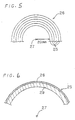
- the oxide superconductive wire 21 was wound for 5 turns on a core 20 of a bobbin 19 as shown in Figs. 3 and 4.
- the oxide superconductive wire 21 was wound with the oxide superconductive layer 23 positioned outside and the base 24 positioned inside about the center of the core 20, that is, the flexural center 22, as shown in Fig. 4.
- the diameter of the core 20 was 40 mm.
- the heat-treated oxide superconductive wire 21 was cooled, and since the thermal expansion coefficient of the base 24 was larger than that of the oxide superconductive layer 23, a preliminary compressive strain was applied in the longitudinal direction of the oxide superconductive layer 23.
- the oxide superconductive wire 21 wound around the bobbin 19 was dipped in liquid nitrogen and the critical current was measured, which was 5.5 A.
- Example 1 When the oxide superconductive wire provided by Example 1 was cut in an appropriate length without winding, and the critical current in liquid nitrogen of the linear wire was measured, which was 6.0 A.
- the oxide superconductive wire 21 was wound around the core 20 of the bobbin 19 under the same condition as in Example 1 except that the oxide superconductive layer 23 was positioned inside.
- the critical current of the oxide superconductive wire 21 wound around the bobbin 19 was measured under the same condition, which was 4.75 A.
- An oxide superconductive wire was provided by using the same base and the same film forming conditions as in Example 1. By using the oxide superconductive wire, a superconductive coil was fabricated as will be described below.
- an oxide superconductive wire 25 was wound for 5 layers to provide a coil 26, starting from a circumference distant from the center 27 of the coil 26 by the radius of 20 mm. At this time, the oxide superconductive wire was wound with the oxide superconductive layer 28 positioned outside and the base 29 positioned inside.
- the coil 26 provided in this manner was dipped in liquid nitrogen, and the critical current was measured, which was 25 A.
- a coil was fabricated under the same condition as in Embodiment 1 except that the wire was wound with the oxide superconductive layer 28 positioned inside.
- the critical current was measured under the same condition, which value was 8.8 A.
- the oxide superconductive wire can be advantageously applied to products such as superconductive magnets for investigation, magnets for nuclear magnetic resonance diagnostic apparatus, superconductive cables, superconductive generators, superconductive transformers, superconductive coils for linear motor cars, superconductive coils for electromagnetically propelled ships.
Landscapes
- Engineering & Computer Science (AREA)
- Power Engineering (AREA)
- Manufacturing & Machinery (AREA)
- Superconductors And Manufacturing Methods Therefor (AREA)
Description
Claims (3)
- A method of manufacturing an oxide superconductive wire comprising the steps of preparing a single, longitudinal, flexible, tape-type base (2; 12; 24; 29; 34) and forming an oxide superconductive layer (1; 13; 23; 28; 33) on said single base through at least processes of heat treatment and succeeding cooling, with a compressive strain in said oxide superconductive layer of said wire in the longitudinal direction, wherein said compressive strain is applied to said superconductive layer by heat treating said oxide superconductive layer and said base with tensile strain applied to the oxide superconductive layer and the base in a non-bent state to release stress existing in the oxide superconductive layer and by cooling the oxide superconductive layer and said base, based on physical action provided by said base.
- A coil for generating a magnetic field, comprising an oxide superconductive wire (21; 25; 30) having an oxide superconductive layer (1; 13; 23; 28) formed on a single, longitudinal, flexible, tape-type base, wherein said oxide superconductive layer has a compressive strain in the longitudinal direction of said wire in said coil, and wherein said oxide superconductive wire is bent with said oxide superconductive layer positioned outside and said base positioned inside about a flexural center.
- A cable comprising an oxide superconductive wire (21; 25; 30) having an oxide superconductive layer (1; 13; 23; 28) formed on a single, longitudinal, flexible, tape-type base, wherein said oxide superconductive layer has a compressive strain in the longitudinal direction of said wire in said cable, and wherein said oxide superconductive wire is wound spirally on a surface of a longitudinal body with said oxide superconductive layer positioned outside and said base positioned inside about a flexural center.
Applications Claiming Priority (10)
| Application Number | Priority Date | Filing Date | Title |
|---|---|---|---|
| JP82556/89 | 1989-03-31 | ||
| JP8255689 | 1989-03-31 | ||
| JP8255689 | 1989-03-31 | ||
| JP18320789 | 1989-07-14 | ||
| JP183207/89 | 1989-07-14 | ||
| JP18320789 | 1989-07-14 | ||
| JP58814/90 | 1990-03-09 | ||
| JP5881490 | 1990-03-09 | ||
| JP02058814A JP3113256B2 (en) | 1989-03-31 | 1990-03-09 | Oxide superconducting wire, method for producing the same, and product using the same |
| PCT/JP1990/000422 WO1990012408A1 (en) | 1989-03-31 | 1990-03-29 | Oxide superconductor wire, method of producing the same and article produced therefrom |
Publications (4)
| Publication Number | Publication Date |
|---|---|
| EP0423354A1 EP0423354A1 (en) | 1991-04-24 |
| EP0423354A4 EP0423354A4 (en) | 1992-04-22 |
| EP0423354B1 EP0423354B1 (en) | 1996-09-11 |
| EP0423354B2 true EP0423354B2 (en) | 2000-10-25 |
Family
ID=27296694
Family Applications (1)
| Application Number | Title | Priority Date | Filing Date |
|---|---|---|---|
| EP90905634A Expired - Lifetime EP0423354B2 (en) | 1989-03-31 | 1990-03-29 | Oxide superconductor wire, method of producing the same and article produced therefrom |
Country Status (6)
| Country | Link |
|---|---|
| US (2) | US5312802A (en) |
| EP (1) | EP0423354B2 (en) |
| JP (1) | JP3113256B2 (en) |
| CA (1) | CA2030558C (en) |
| DE (1) | DE69028471T3 (en) |
| WO (1) | WO1990012408A1 (en) |
Families Citing this family (30)
| Publication number | Priority date | Publication date | Assignee | Title |
|---|---|---|---|---|
| US5661114A (en) | 1993-04-01 | 1997-08-26 | American Superconductor Corporation | Process of annealing BSCCO-2223 superconductors |
| US6194352B1 (en) | 1994-01-28 | 2001-02-27 | American Superconductor Corporation | Multifilament composite BSCCO oxide superconductor |
| US5531015A (en) * | 1994-01-28 | 1996-07-02 | American Superconductor Corporation | Method of making superconducting wind-and-react coils |
| DE19727343A1 (en) * | 1996-07-11 | 1998-01-15 | Alsthom Cge Alcatel | High current carrying capacity superconductive layer production |
| US5987342A (en) * | 1996-08-30 | 1999-11-16 | American Superconductor Corporation | Laminated superconducting ceramic tape |
| US6110606A (en) | 1996-08-30 | 2000-08-29 | American Superconductor Corporation | Cryogen protected superconducting ceramic tape |
| US5801124A (en) * | 1996-08-30 | 1998-09-01 | American Superconductor Corporation | Laminated superconducting ceramic composite conductors |
| US6444917B1 (en) | 1999-07-23 | 2002-09-03 | American Superconductor Corporation | Encapsulated ceramic superconductors |
| JP4534276B2 (en) * | 1999-10-01 | 2010-09-01 | 住友電気工業株式会社 | Oxide superconducting wire connection method |
| US6745059B2 (en) | 2001-11-28 | 2004-06-01 | American Superconductor Corporation | Superconductor cables and magnetic devices |
| JPWO2003050826A1 (en) * | 2001-12-10 | 2005-04-21 | 三菱電機株式会社 | Metal substrate for oxide superconducting thick film and method for producing the same |
| JP4652721B2 (en) * | 2004-05-21 | 2011-03-16 | 古河電気工業株式会社 | Superconducting coil |
| DE102004040754A1 (en) * | 2004-08-23 | 2006-03-09 | Siemens Ag | Rectangular coil of ribbon-shaped superconductors with HochTc superconductor material and use thereof |
| JP4732162B2 (en) * | 2005-12-27 | 2011-07-27 | 株式会社フジクラ | Oxide superconducting conductor and manufacturing method thereof |
| JP5115778B2 (en) * | 2006-01-16 | 2013-01-09 | 住友電気工業株式会社 | Superconducting cable |
| JP2008060143A (en) * | 2006-08-29 | 2008-03-13 | Kobe Steel Ltd | Superconducting coil and manufacturing method thereof |
| JP2008153372A (en) * | 2006-12-15 | 2008-07-03 | Sumitomo Electric Ind Ltd | Superconducting coil and superconducting equipment provided with the superconducting coil |
| JP5040668B2 (en) * | 2008-01-16 | 2012-10-03 | 住友電気工業株式会社 | Superconducting tape manufacturing method and superconducting tape manufacturing apparatus |
| JP2010113919A (en) * | 2008-11-05 | 2010-05-20 | Chubu Electric Power Co Inc | Superconducting tape wire and method of manufacturing the same, and superconducting coil |
| JP5677116B2 (en) * | 2011-02-08 | 2015-02-25 | 株式会社フジクラ | High temperature superconducting coil |
| RU2471269C1 (en) * | 2011-12-07 | 2012-12-27 | Федеральное государственное бюджетное учреждение науки Институт физики твердого тела Российской академии наук (ИФТТ РАН) | Method of producing high-temperature superconductor in aluminium-aluminium oxide system |
| KR101308138B1 (en) * | 2012-01-26 | 2013-09-12 | 창원대학교 산학협력단 | High Temperature Superconductor DC reactor |
| JP2013242993A (en) * | 2012-05-18 | 2013-12-05 | Tohoku Univ | Characteristics control method of rare earth-based superconductive wire |
| DE102012223366A1 (en) * | 2012-12-17 | 2014-06-18 | Siemens Aktiengesellschaft | Superconducting coil device with coil winding and contacts |
| KR101459583B1 (en) * | 2013-09-11 | 2014-11-10 | 주식회사 서남 | Superconductor and method for manufacturing the same |
| JP2017147189A (en) * | 2016-02-19 | 2017-08-24 | 昭和電線ケーブルシステム株式会社 | Oxide superconducting wire and method for producing oxide superconducting wire |
| WO2019245646A1 (en) * | 2018-06-22 | 2019-12-26 | Florida State University Research Foundation, Inc. | System and method to manage high stresses in bi-2212 wire wound compact superconducting magnets |
| CN109273585A (en) * | 2018-08-28 | 2019-01-25 | 中国科学院上海微系统与信息技术研究所 | Thin film deposition method and Josephson junction preparation method |
| CN111696721B (en) * | 2020-06-05 | 2021-08-20 | 上海超导科技股份有限公司 | Pinning center introducing structure and method suitable for large-scale production and superconducting tape |
| CN112420275A (en) * | 2020-11-10 | 2021-02-26 | 兰州大学 | Method for increasing irreversible strain of superconducting tape and superconducting tape |
Family Cites Families (9)
| Publication number | Priority date | Publication date | Assignee | Title |
|---|---|---|---|---|
| NL6614866A (en) * | 1965-11-08 | 1967-05-09 | ||
| JPS54147491A (en) * | 1978-05-10 | 1979-11-17 | Hitachi Ltd | Preparation of compound superconductive wire |
| EP0283313B1 (en) * | 1987-03-20 | 1994-02-23 | Fujikura Ltd. | Method of producing oxide superconducting wire and oxide superconducting wire produced by this method |
| JPS63274017A (en) * | 1987-04-30 | 1988-11-11 | Tdk Corp | Superconductive wire material |
| JP2703227B2 (en) * | 1987-05-11 | 1998-01-26 | 株式会社東芝 | Superconductor device |
| JPS63310511A (en) * | 1987-06-12 | 1988-12-19 | Hitachi Ltd | High temperature superconductor membrane |
| JPS6452327A (en) * | 1987-08-22 | 1989-02-28 | Sumitomo Electric Industries | Superconductive material |
| AU610260B2 (en) * | 1987-10-16 | 1991-05-16 | Furukawa Electric Co. Ltd., The | Oxide superconductor shaped body and method of manufacturing the same |
| DE3829227A1 (en) * | 1988-08-29 | 1990-03-01 | Kabelmetal Electro Gmbh | SUPER-CONDUCTING LONG-STRETCHED GOODS FROM A COATED CORRUGATED METAL TUBE |
-
1990
- 1990-03-09 JP JP02058814A patent/JP3113256B2/en not_active Expired - Lifetime
- 1990-03-29 US US07/613,868 patent/US5312802A/en not_active Expired - Lifetime
- 1990-03-29 DE DE69028471T patent/DE69028471T3/en not_active Expired - Lifetime
- 1990-03-29 CA CA002030558A patent/CA2030558C/en not_active Expired - Fee Related
- 1990-03-29 WO PCT/JP1990/000422 patent/WO1990012408A1/en not_active Ceased
- 1990-03-29 EP EP90905634A patent/EP0423354B2/en not_active Expired - Lifetime
-
1994
- 1994-02-15 US US08/196,615 patent/US5372991A/en not_active Expired - Lifetime
Also Published As
| Publication number | Publication date |
|---|---|
| DE69028471T2 (en) | 1997-02-06 |
| JPH03138817A (en) | 1991-06-13 |
| JP3113256B2 (en) | 2000-11-27 |
| CA2030558C (en) | 1997-02-25 |
| CA2030558A1 (en) | 1990-10-01 |
| US5372991A (en) | 1994-12-13 |
| EP0423354B1 (en) | 1996-09-11 |
| WO1990012408A1 (en) | 1990-10-18 |
| DE69028471D1 (en) | 1996-10-17 |
| US5312802A (en) | 1994-05-17 |
| EP0423354A4 (en) | 1992-04-22 |
| DE69028471T3 (en) | 2001-05-23 |
| EP0423354A1 (en) | 1991-04-24 |
Similar Documents
| Publication | Publication Date | Title |
|---|---|---|
| EP0423354B1 (en) | Oxide superconductor wire, method of producing the same and article produced therefrom | |
| US6603379B1 (en) | Superconducing wind-and-react-coils and methods of manufacture | |
| JP3474602B2 (en) | Superconducting conductor | |
| US8061016B2 (en) | Superconducting coil fabrication | |
| JP3342739B2 (en) | Oxide superconducting conductor, method of manufacturing the same, and oxide superconducting power cable having the same | |
| EP0417329B1 (en) | Method of producing an oxide superconducting wire | |
| US6510604B1 (en) | Superconducting cables experiencing reduced strain due to bending | |
| JP3386942B2 (en) | Oxide superconducting coil and manufacturing method thereof | |
| GB2220295A (en) | Superconducting articles | |
| CA2063282C (en) | High temperature superconducting wire using oxide superconductive material | |
| JP3283106B2 (en) | Structure of current supply terminal for oxide superconducting conductor | |
| JP3369225B2 (en) | Method for producing oxide high-temperature superconducting wire | |
| JP3501828B2 (en) | Manufacturing method of oxide superconducting conductor | |
| EP0742595B1 (en) | Method of making a metal impregnated superconductor | |
| JP3144990B2 (en) | Conductor structure of oxide superconducting power cable | |
| JP2986107B2 (en) | Method of manufacturing oxide superconducting wire and method of manufacturing product using oxide superconducting wire | |
| JP2585366B2 (en) | Oxide superconducting wire | |
| US6387525B1 (en) | Self insulating substrate tape | |
| EP0644601A2 (en) | Oxide superconductor and method of fabricating the same | |
| JP3032771B2 (en) | Superconducting coil manufacturing method | |
| JP3248190B2 (en) | Oxide superconducting wire, its manufacturing method and its handling method | |
| EP0698930A1 (en) | Oxide superconductor and fabrication method of the same | |
| JPH117845A (en) | Superconducting wire | |
| JPH04292809A (en) | Multicore superconductive wire |
Legal Events
| Date | Code | Title | Description |
|---|---|---|---|
| PUAI | Public reference made under article 153(3) epc to a published international application that has entered the european phase |
Free format text: ORIGINAL CODE: 0009012 |
|
| 17P | Request for examination filed |
Effective date: 19901130 |
|
| AK | Designated contracting states |
Kind code of ref document: A1 Designated state(s): DE FR GB |
|
| A4 | Supplementary search report drawn up and despatched |
Effective date: 19920305 |
|
| AK | Designated contracting states |
Kind code of ref document: A4 Designated state(s): DE FR GB |
|
| 17Q | First examination report despatched |
Effective date: 19931015 |
|
| GRAG | Despatch of communication of intention to grant |
Free format text: ORIGINAL CODE: EPIDOS AGRA |
|
| GRAG | Despatch of communication of intention to grant |
Free format text: ORIGINAL CODE: EPIDOS AGRA |
|
| GRAH | Despatch of communication of intention to grant a patent |
Free format text: ORIGINAL CODE: EPIDOS IGRA |
|
| GRAH | Despatch of communication of intention to grant a patent |
Free format text: ORIGINAL CODE: EPIDOS IGRA |
|
| GRAA | (expected) grant |
Free format text: ORIGINAL CODE: 0009210 |
|
| AK | Designated contracting states |
Kind code of ref document: B1 Designated state(s): DE FR GB |
|
| ET | Fr: translation filed | ||
| REF | Corresponds to: |
Ref document number: 69028471 Country of ref document: DE Date of ref document: 19961017 |
|
| PLBI | Opposition filed |
Free format text: ORIGINAL CODE: 0009260 |
|
| PLBF | Reply of patent proprietor to notice(s) of opposition |
Free format text: ORIGINAL CODE: EPIDOS OBSO |
|
| 26 | Opposition filed |
Opponent name: SIEMENS AG Effective date: 19970609 |
|
| PLBF | Reply of patent proprietor to notice(s) of opposition |
Free format text: ORIGINAL CODE: EPIDOS OBSO |
|
| PLAW | Interlocutory decision in opposition |
Free format text: ORIGINAL CODE: EPIDOS IDOP |
|
| PLAW | Interlocutory decision in opposition |
Free format text: ORIGINAL CODE: EPIDOS IDOP |
|
| PUAH | Patent maintained in amended form |
Free format text: ORIGINAL CODE: 0009272 |
|
| STAA | Information on the status of an ep patent application or granted ep patent |
Free format text: STATUS: PATENT MAINTAINED AS AMENDED |
|
| 27A | Patent maintained in amended form |
Effective date: 20001025 |
|
| AK | Designated contracting states |
Kind code of ref document: B2 Designated state(s): DE FR GB |
|
| ET3 | Fr: translation filed ** decision concerning opposition | ||
| REG | Reference to a national code |
Ref country code: GB Ref legal event code: IF02 |
|
| PGFP | Annual fee paid to national office [announced via postgrant information from national office to epo] |
Ref country code: GB Payment date: 20090325 Year of fee payment: 20 |
|
| PGFP | Annual fee paid to national office [announced via postgrant information from national office to epo] |
Ref country code: DE Payment date: 20090327 Year of fee payment: 20 |
|
| PGFP | Annual fee paid to national office [announced via postgrant information from national office to epo] |
Ref country code: FR Payment date: 20090316 Year of fee payment: 20 |
|
| REG | Reference to a national code |
Ref country code: GB Ref legal event code: PE20 Expiry date: 20100328 |
|
| PG25 | Lapsed in a contracting state [announced via postgrant information from national office to epo] |
Ref country code: GB Free format text: LAPSE BECAUSE OF EXPIRATION OF PROTECTION Effective date: 20100328 |
|
| PG25 | Lapsed in a contracting state [announced via postgrant information from national office to epo] |
Ref country code: DE Free format text: LAPSE BECAUSE OF EXPIRATION OF PROTECTION Effective date: 20100329 |