EP0423085B1 - Automatischer Leckdetektionsapparat für Arbeitsfluide von Produktions- und/oder Forschungskraftwerken, insbesondere Energiekraftwerken - Google Patents
Automatischer Leckdetektionsapparat für Arbeitsfluide von Produktions- und/oder Forschungskraftwerken, insbesondere Energiekraftwerken Download PDFInfo
- Publication number
- EP0423085B1 EP0423085B1 EP90830452A EP90830452A EP0423085B1 EP 0423085 B1 EP0423085 B1 EP 0423085B1 EP 90830452 A EP90830452 A EP 90830452A EP 90830452 A EP90830452 A EP 90830452A EP 0423085 B1 EP0423085 B1 EP 0423085B1
- Authority
- EP
- European Patent Office
- Prior art keywords
- alarm
- sensors
- telecamera
- thermocamera
- plants
- Prior art date
- Legal status (The legal status is an assumption and is not a legal conclusion. Google has not performed a legal analysis and makes no representation as to the accuracy of the status listed.)
- Expired - Lifetime
Links
Images

Classifications
-
- G—PHYSICS
- G21—NUCLEAR PHYSICS; NUCLEAR ENGINEERING
- G21C—NUCLEAR REACTORS
- G21C17/00—Monitoring; Testing ; Maintaining
- G21C17/02—Devices or arrangements for monitoring coolant or moderator
- G21C17/022—Devices or arrangements for monitoring coolant or moderator for monitoring liquid coolants or moderators
-
- Y—GENERAL TAGGING OF NEW TECHNOLOGICAL DEVELOPMENTS; GENERAL TAGGING OF CROSS-SECTIONAL TECHNOLOGIES SPANNING OVER SEVERAL SECTIONS OF THE IPC; TECHNICAL SUBJECTS COVERED BY FORMER USPC CROSS-REFERENCE ART COLLECTIONS [XRACs] AND DIGESTS
- Y02—TECHNOLOGIES OR APPLICATIONS FOR MITIGATION OR ADAPTATION AGAINST CLIMATE CHANGE
- Y02E—REDUCTION OF GREENHOUSE GAS [GHG] EMISSIONS, RELATED TO ENERGY GENERATION, TRANSMISSION OR DISTRIBUTION
- Y02E30/00—Energy generation of nuclear origin
- Y02E30/30—Nuclear fission reactors
Definitions
- the present invention relates to an apparatus for automatically monitoring and detecting leaks of fluids from lines or container under pressure and temperature effects, said apparatus being also adapted to detect in real or almost real time such leaks with a high reliability.
- More particularly the invention concerns the monitoring of the leakages of the cooling fluid for the primary circuit of the nuclear plants formed of pressurized-water reactor (PWR) and boiling-water reactors (BWR) for the production of electric energy.
- PWR pressurized-water reactor
- BWR boiling-water reactors
- the leak detection methods used at the present are:
- None of the above mentioned methods is adapted to allow the leakage to be monitored, detected and evaluated.
- the most reliable method used at the present time to detect leakages is monitoring the bilge flow. Monitoring the environmental radioactivity of the content is considered reliable but considerably limitative in controlling BWR which originates un number of undesired alarms.
- This invention seeks to provide a high-reliability system such as to allow: detecting the extent of the leakage in real or nearly real time; monitoring the nuclear plant and the most involved areas thereof; maintaining the several parts of the production system without interrupting the monitoring action; eliminating the undesired alarms; and avoiding the masking phenomenon which makes the control system blind.
- an apparatus consisting of one or more telecameras, one or more thermocameras and a chemical-excitation mass spectrometer which are connected to one or more computers suitably programmed to process signals, to supply alarm signals of different type and to collect information about the events.
- the apparatus is based upon the control of the variations of some physical parameters which are typical of the plant and/or the checked components, and the functional characteristics which are typical of the fluids when released from the socalled holding barriers such as pipes, valves, reservoirs, a.s.o.
- control is executed through three lines provided with different and independent sensors adapted to detect completely different, physical phenomena.
- the three lines analyze signals typical of the leakage of fluids to the environment as follows:
- Coupling all of the three lines of sensors or one of the first two lines with the third line makes the system highly reliable.
- a central computer which processes the signals and allow an automatic control to be effected at very short signal times.
- the first two lines of sensors are adpted to detect, to locate and to evaluate approximately the leaks of fluids
- the third line of sensors is adapted to locate and to estimate the amount of the leaked fluids and to determine its origin. In any case, by analyzing completely different parameters, events such as to mask the real signal in all of the three lines of sensors or to simulate false material-leak signals are very difficult to take place.
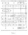
- control apparatus With reference to Fig. 1, the control apparatus according to the invention is shown in its basic configuration but can also have a more complex configuration, namely:
- an intake station CA for the atmospheric fluid of the environment flowing through anti-dust filter F and feeding line CR heated to avoid a condensation along its extension and both conveying a part of the intaken fluid into mass spectrometer SM and ejecting the remaining part of the fluid through an integral filter FG into the atmosphere in order to avoid storing effects in the intaken line.
- Chemical-excitation mass spectrometer SM analyzes the composition of the atmospheric fluid and is adapted to detect the modifications thereof. Said mass spectrometer is associated to a processing computer CG. The apparatus further comprises:
- the apparatus is designed such as to allow an automatic operation after initialization and selection of the control parameters.
- the initialization should be executed by a skilled in the art according to the specification of the apparatus to be controlled and the safety rules. Once initialized the system, it is no longer possible to change the parameters during the operation. The apparatus should be put out of operation and the initialization procedures should be repeated to change the selected parameters.
- the apparatus is operated only by a skilled in the art.
- the computer asks the operator the starting code.
- the operator digitizes the code and the computer shows on a display a list of checking instructions to be executed before carrying on.
- the apparatus is operated.
- the apparatus After data has been set the apparatus is ready to operate automatically.
- a predetermined number of images are received, digitized at about 11 MHz and divided in 512x512 or 1024x1024 pixels or other standard.
- connection can be re-established by the operator. Positive check. Carry on. Positions 1, 2, 3 are "procedure P1".
- the resulting image is transformed into binary code.
- the maximum value (255) is assigned to the pixels exceeding the predetermined threshold value, and the minimum value (0) is assigned to the pixels under said threshold value.
- a pre-alarm signal is generated. Such signal is supplied to the light alarm device and to the printer.
- the computer starts the videorecorder.
- thermocamera TM At the end of any cycle the computer switches over the thermocamera TM.
- the stop of the image receiving apparatus can be executed only by an authorized operator and such operation is in any case signalled.
- a predetermined number of images are received, digitized at about 11 MHz and divided in 512x512 or 1024x1024 pixels or other standard.
- thermocamera If 90% of the pixels have intensity lower than 5 or greater than 250, the following writing preceded by an acoustic signal appears on the videodisplay: "abnormal operating condition - check thermocamera"
- thermocamera outer signal of white alarm
- connection can be re-established by the operator. Positive check. Carry on.
- Positions 1, 2, 3 are "procedure P1".
- the resulting image is transformed into binary code.
- the mean intensity is calculated and the maximum value (255) is assigned to the pixels exceeding the predetermined threshold value Sg3, and the minimum value (0) is assigned to the pixels under said threshold value. Further all pixels exceeding threshold Sg4 are counted. Resulting data is reported as histogram.
- images "A” and "B” are reference images with which the successive images "Ci" are compared).
- Item 8 is procedure P3.
- the resulting image is transformed into binary code.
- the maximum value (255) is assigned to the pixels exceeding the predetermined threshold value, and the minimum value (0) is assigned to the pixels under said threshold value.
- the pixels having intensity 255 are counted.
- the result (D1) is fed by the computer to the printer sector by sector.
- a pre-alarm signal is generated. Such signal is supplied to the light alarm device and to the printer.
- the computer starts the videorecorder.
- the alarm signals and the videorecorder are active in any case. Only the operator can re-establish the normal conditions. In any case a further image is received.
- the stop of the image receiving apparatus can be executed only by an authorized operator and such operation is in any case signalled.
- the analysis program is initialized by supplying the computer of the mass spectrometer with:
- the environmental fluid is first drawn.
- the fluid is analyzed.
- the alarm signals can be combined in different ways according to the safety requirements of the plant or the checked component.
- the central computer enables cyclically the analysis on the different control lines in the predetermined time.
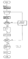
- Fig. 5 the block diagram of the different steps forming the operating cycle of the apparatus is shown.
- the invention provides a reliable, complementary, decisive apparatus adapted to supply signals in real or nearly real time and to control fluid leaks, while avoiding that a not effected alarm signalling causes a disaster.
Landscapes
- Physics & Mathematics (AREA)
- Engineering & Computer Science (AREA)
- Plasma & Fusion (AREA)
- General Engineering & Computer Science (AREA)
- High Energy & Nuclear Physics (AREA)
- Examining Or Testing Airtightness (AREA)
- Investigating Or Analysing Materials By Optical Means (AREA)
Claims (8)
- Gerät zur automatischen Erfassung undichter Stellen für die kontinuierliche Überwachung von Prozeßflüssigkeiten aus Produktions- und/oder Forschungsanlagen, insbesondere Energieerzeugungsanlagen, mit einer Vielzahl an operativ und strukturell unabhängigen Sensoren, welche sich in bestimmten Bereichen und/oder Einzelaggregaten bzw. Bauteilen der zu kontrollierenden Anlagen befinden, zu denen Datenverarbeitungsvorrichtungen gehören zur Verarbeitung von Daten, welche durch die Sensoren geliefert werden, und zum Vergleichen dieser Daten mit Referenzdaten,
wobei die Erfassungs- und Überwachungsleitungen der Sensoren aus einer ersten Gruppe an Sensoren gebildet werden, welche visuelle Bilder des zu kontrollierenden Aggregats im sichtbaren Spektralbereich durch eine Fernsehkamera (TC) erfassen, einer zweiten Gruppe an Sensoren, welche Thermobilder desselben Aggregats im Infrarotspektralbereich durch eine Thermokamera (TM) erfassen, sowie aus einer dritten Gruppe an Sensoren, welche dazu geeignet sind, die Veränderungen in der Zusammensetzung der Umgebungsatmosphäre in qualitativer und quantitativer Hinsicht durch ein chemisches Anregungsmassenspektrometer (SM) zu erfassen,
wobei dieses Gerät ferner mit Fernsehkamera- und Thermokameraschnittstellen versehen ist, welche es erlauben, das Bild zu digitalisieren und einem Rechner (CC) in digitaler Form zuzuführen, so daß die Daten von den drei Gruppen an Sensoren kontinuierlich durch den Rechner (CC) kontrolliert werden, welcher jedes Ereignis signalisiert und abspeichert und jeglichen Alarm und/oder Steuerung auslöst. - Gerät nach Anspruch 1, dadurch gekennzeichnet, daß die Fernsehkamera (TC) zur Erfassung derjenigen Rauchgase ausgelegt ist, welche durch die Kondensation der Dämpfe des ausgelaufenen Fluids und/oder eine undichte Stelle für eine Flüssigkeit und/oder eine Veränderung der Oberflächen der Einzelaggregate oder der Umgebung infolge der Kondensation oder der Reaktivität des Fluids erzeugt werden.
- Gerät nach Anspruch 1 oder 2, dadurch gekennzeichnet, daß die Thermokamera (TM) das Wärmebild der Dämpfe des ausgelaufenen Fluids und/oder eine undichte Stelle der Flüssigkeit und/oder eine Veränderung der Einzelaggregate oder der Umgebung erfaßt.
- Gerät nach Anspruch 1 bis 3, dadurch gekennzeichnet, daß die Fernsehkamera (TC) und die Thermokamera (TM) sich in einem abgeschirmten Gehäuse befinden, welches mit Thermostaten versehen ist, und mit einem automatischen Einrichtsystem zur Erreichung eines weiteren Beobachtungsfeldes verbunden sein kann.
- Gerät nach den Ansprüchen 1 bis 4, dadurch gekennzeichnet, daß die Fernsehkamera (TC) und die Thermokamera (TM) mit einer Referenzsichteinrichtung (TR), welche aus einem Feld an Halogenlampen besteht, die durch einen semitransparenten Schirm abgeschirmt sind, und mit einer automatischen Beleuchtungsvorrichtung versehen sind, welche infolge der Unterbrechung aufgrund der Unterbrechung des Glühfadens von einer oder mehrerer Lampen des Feldes arbeitet.
- Gerät nach Anspruch 1 bis 5, dadurch gekennzeichnet, daß das Massenspektrometer (SM) Analysen der geprüften Fluide in bestimmten Intervallen ausführt, die Ergebnisse mit Referenzdaten vergleicht und ein Alarmsignal als eine Funktion des Vergleichs abgibt.
- Gerät nach Anspruch 1 bis 6, dadurch gekennzeichnet, daß alle Betriebsschritte der Kontrollvorrichtung (CC) in graphischer Form (ST, VR) mit gleichzeitigen visuellen und akustischen Alarmsignalen aufgezeichnet werden.
- Gerät nach Anspruch 1 bis 7, dadurch gekennzeichnet, daß die Alarmsignale in Echtzeit oder nahezu Echtzeit ausgelöst werden und zueinander unterschiedlich ausgelegt werden gemäß der ausgelaufenen Menge, deren örtlicher Lage und der Gleichzeitigkeit jedes abnormalen Zustandes, welcher durch eine oder mehrere Sensorgruppen erfaßt werden.
Applications Claiming Priority (2)
| Application Number | Priority Date | Filing Date | Title |
|---|---|---|---|
| IT4845589 | 1989-10-13 | ||
| IT04845589A IT1237814B (it) | 1989-10-13 | 1989-10-13 | Apparecchiatura per il rilevamento automatico di fughe di fluidi di processo da impianti di produzione e/o ricerca,particolarmente impianti energetici |
Publications (3)
| Publication Number | Publication Date |
|---|---|
| EP0423085A2 EP0423085A2 (de) | 1991-04-17 |
| EP0423085A3 EP0423085A3 (en) | 1992-01-02 |
| EP0423085B1 true EP0423085B1 (de) | 1995-08-09 |
Family
ID=11266641
Family Applications (1)
| Application Number | Title | Priority Date | Filing Date |
|---|---|---|---|
| EP90830452A Expired - Lifetime EP0423085B1 (de) | 1989-10-13 | 1990-10-11 | Automatischer Leckdetektionsapparat für Arbeitsfluide von Produktions- und/oder Forschungskraftwerken, insbesondere Energiekraftwerken |
Country Status (5)
| Country | Link |
|---|---|
| US (1) | US5210526A (de) |
| EP (1) | EP0423085B1 (de) |
| AT (1) | ATE126383T1 (de) |
| DE (1) | DE69021486D1 (de) |
| IT (1) | IT1237814B (de) |
Families Citing this family (15)
| Publication number | Priority date | Publication date | Assignee | Title |
|---|---|---|---|---|
| EP0666542A3 (de) * | 1994-02-04 | 1996-05-15 | Fuji Facom Corp | Multimediensystem zur Überwachung und zur Steuerung von Verfahren. |
| US5572671A (en) * | 1995-02-17 | 1996-11-05 | Base Ten Systems, Inc. | Method for operating application software in a safety critical environment |
| GB2314623B (en) * | 1995-03-28 | 1999-11-03 | Somerset Technical Lab Ltd | Method and apparatus for detecting and locating fluid leaks through the wall of a vessel |
| AU711222B2 (en) * | 1995-03-28 | 1999-10-07 | Somerset Technical Laboratories Limited | Method and apparatus for detecting irregularities on or in the wall of a vessel |
| US5886636A (en) * | 1997-12-17 | 1999-03-23 | A-Acme, Inc. | Moisture detection and source identification method for structures |
| DE19823599A1 (de) * | 1998-05-27 | 1999-12-09 | Beb Erdgas & Erdoel Gmbh | Verfahren und Vorrichtungen zur Überwachung von Anlagen der chemischen Industrie |
| US20040016700A1 (en) * | 2002-07-23 | 2004-01-29 | Benjamin Kellam | System and a method for determining integrity of a dialyzer |
| US20050254548A1 (en) * | 2002-09-26 | 2005-11-17 | Mirko Appel | Method and apparatus for monitoring a technical installation, especially for carrying out diagnosis |
| US8043562B2 (en) | 2003-12-08 | 2011-10-25 | Ortho-Clinical Diagnostics, Inc. | Analyzer having removable holders or a centrifuge |
| US7257145B2 (en) * | 2005-06-02 | 2007-08-14 | Westinghouse Electric Co Llc | Spectroscopy-based safety system and method for a vacuum arc remelt furnace |
| US10373470B2 (en) | 2013-04-29 | 2019-08-06 | Intelliview Technologies, Inc. | Object detection |
| EP2992365B1 (de) | 2013-04-29 | 2018-04-04 | Intelliview Technologies Inc. | Objektdetektion |
| CA2847707C (en) | 2014-03-28 | 2021-03-30 | Intelliview Technologies Inc. | Leak detection |
| US10943357B2 (en) | 2014-08-19 | 2021-03-09 | Intelliview Technologies Inc. | Video based indoor leak detection |
| CN110275473A (zh) * | 2019-07-25 | 2019-09-24 | 安徽理工大学 | 智能化化工安全生产监控系统 |
Family Cites Families (4)
| Publication number | Priority date | Publication date | Assignee | Title |
|---|---|---|---|---|
| JPS516083A (en) * | 1974-07-03 | 1976-01-19 | Nippon Kokan Kk | Ryutaino morekenchisochi |
| JPS58161888A (ja) * | 1982-03-19 | 1983-09-26 | 動力炉・核燃料開発事業団 | 破損燃料位置検知装置 |
| JPS6042631A (ja) * | 1983-08-19 | 1985-03-06 | Mitsubishi Electric Corp | 水漏れ監視装置 |
| US4857261A (en) * | 1988-08-31 | 1989-08-15 | Westinghouse Electric Corp. | Reactor vessel head area monitoring system |
-
1989
- 1989-10-13 IT IT04845589A patent/IT1237814B/it active IP Right Grant
-
1990
- 1990-10-11 DE DE69021486T patent/DE69021486D1/de not_active Expired - Lifetime
- 1990-10-11 AT AT90830452T patent/ATE126383T1/de active
- 1990-10-11 EP EP90830452A patent/EP0423085B1/de not_active Expired - Lifetime
- 1990-10-11 US US07/596,078 patent/US5210526A/en not_active Expired - Fee Related
Also Published As
| Publication number | Publication date |
|---|---|
| IT8948455A0 (it) | 1989-10-13 |
| EP0423085A2 (de) | 1991-04-17 |
| IT8948455A1 (it) | 1991-04-13 |
| IT1237814B (it) | 1993-06-18 |
| EP0423085A3 (en) | 1992-01-02 |
| DE69021486D1 (de) | 1995-09-14 |
| US5210526A (en) | 1993-05-11 |
| ATE126383T1 (de) | 1995-08-15 |
Similar Documents
| Publication | Publication Date | Title |
|---|---|---|
| EP0423085B1 (de) | Automatischer Leckdetektionsapparat für Arbeitsfluide von Produktions- und/oder Forschungskraftwerken, insbesondere Energiekraftwerken | |
| FI79199C (fi) | Foerfarande och anordning foer styrning av ett komplext olinjaert processreglersystem. | |
| EP0351833A2 (de) | Fehlerdiagnosesystem für Anlagen | |
| US5070468A (en) | Plant fault diagnosis system | |
| US4585609A (en) | Method of monitoring an electricity generating station equipped with a nuclear reactor | |
| EP4517780A1 (de) | Überwachungsverfahren und -system für den unfallbetriebszustand eines kernkraftwerkssatzes | |
| EP0925491A1 (de) | Ereignisdetektionssystem und -verfahren | |
| JP2912545B2 (ja) | 加圧水型原子炉および加圧水型原子炉の防御方法 | |
| JP2011145978A (ja) | プラント監視制御システム | |
| JPS6310799B2 (de) | ||
| US4657727A (en) | Fission product barrier emergency event classification and response system | |
| JPH05296869A (ja) | 配管漏洩検出装置 | |
| JPH0298692A (ja) | 手続き選択方法及び手続き実行監視装置 | |
| JPS6212878B2 (de) | ||
| EP0258958B1 (de) | Auffinden eines gebrochenen Brennstabbündels in einem in Betrieb befindlichen Kernreaktor | |
| CN115497655B (zh) | 核电厂火灾工况事故诊断方法、系统及可读存储介质 | |
| US12436078B2 (en) | Aspirating smoke detector with test module | |
| JPH06194493A (ja) | 原子力プラント事故対応支援システム | |
| JPH1130689A (ja) | 漏洩燃料集合体検出装置 | |
| JPH04194788A (ja) | 高速炉の炉内異常検出方法 | |
| JPH02224096A (ja) | プラントの異常時運転支援システム | |
| Yune et al. | Performance Evaluation of RCS Leak Monitoring System for Ulchin Units 1 and 2 | |
| Chang et al. | Development of the on-line operator aid system (oasysm) using rule based expert system and fuzzy logic for nuclear power plants | |
| Macko | Experience with humidity monitoring and leak detection system SMU-V at the Jaslovske Bohunice V-1 NPP | |
| JPS6041757B2 (ja) | 原子力発電所における漏洩検出装置 |
Legal Events
| Date | Code | Title | Description |
|---|---|---|---|
| PUAI | Public reference made under article 153(3) epc to a published international application that has entered the european phase |
Free format text: ORIGINAL CODE: 0009012 |
|
| AK | Designated contracting states |
Kind code of ref document: A2 Designated state(s): AT BE CH DE DK ES FR GB GR LI LU NL SE |
|
| PUAL | Search report despatched |
Free format text: ORIGINAL CODE: 0009013 |
|
| AK | Designated contracting states |
Kind code of ref document: A3 Designated state(s): AT BE CH DE DK ES FR GB GR LI LU NL SE |
|
| RAP1 | Party data changed (applicant data changed or rights of an application transferred) |
Owner name: ENTE PER LE NUOVE TECNOLOGIE, L'ENERGIA E L'AMBIEN |
|
| 17P | Request for examination filed |
Effective date: 19920701 |
|
| 17Q | First examination report despatched |
Effective date: 19930928 |
|
| GRAA | (expected) grant |
Free format text: ORIGINAL CODE: 0009210 |
|
| AK | Designated contracting states |
Kind code of ref document: B1 Designated state(s): AT BE CH DE DK ES FR GB GR LI LU NL SE |
|
| PG25 | Lapsed in a contracting state [announced via postgrant information from national office to epo] |
Ref country code: NL Free format text: LAPSE BECAUSE OF NON-PAYMENT OF DUE FEES Effective date: 19950809 Ref country code: GR Free format text: LAPSE BECAUSE OF FAILURE TO SUBMIT A TRANSLATION OF THE DESCRIPTION OR TO PAY THE FEE WITHIN THE PRESCRIBED TIME-LIMIT Effective date: 19950809 Ref country code: FR Free format text: THE PATENT HAS BEEN ANNULLED BY A DECISION OF A NATIONAL AUTHORITY Effective date: 19950809 Ref country code: ES Free format text: THE PATENT HAS BEEN ANNULLED BY A DECISION OF A NATIONAL AUTHORITY Effective date: 19950809 Ref country code: DK Effective date: 19950809 Ref country code: BE Effective date: 19950809 Ref country code: AT Effective date: 19950809 |
|
| REF | Corresponds to: |
Ref document number: 126383 Country of ref document: AT Date of ref document: 19950815 Kind code of ref document: T |
|
| REF | Corresponds to: |
Ref document number: 69021486 Country of ref document: DE Date of ref document: 19950914 |
|
| PG25 | Lapsed in a contracting state [announced via postgrant information from national office to epo] |
Ref country code: LU Free format text: LAPSE BECAUSE OF NON-PAYMENT OF DUE FEES Effective date: 19951031 |
|
| PGFP | Annual fee paid to national office [announced via postgrant information from national office to epo] |
Ref country code: CH Payment date: 19951031 Year of fee payment: 6 |
|
| PG25 | Lapsed in a contracting state [announced via postgrant information from national office to epo] |
Ref country code: SE Effective date: 19951109 Ref country code: GB Effective date: 19951109 |
|
| PG25 | Lapsed in a contracting state [announced via postgrant information from national office to epo] |
Ref country code: DE Effective date: 19951110 |
|
| NLV1 | Nl: lapsed or annulled due to failure to fulfill the requirements of art. 29p and 29m of the patents act | ||
| EN | Fr: translation not filed | ||
| PLBE | No opposition filed within time limit |
Free format text: ORIGINAL CODE: 0009261 |
|
| STAA | Information on the status of an ep patent application or granted ep patent |
Free format text: STATUS: NO OPPOSITION FILED WITHIN TIME LIMIT |
|
| GBPC | Gb: european patent ceased through non-payment of renewal fee |
Effective date: 19951109 |
|
| 26N | No opposition filed | ||
| PG25 | Lapsed in a contracting state [announced via postgrant information from national office to epo] |
Ref country code: LI Free format text: LAPSE BECAUSE OF FAILURE TO SUBMIT A TRANSLATION OF THE DESCRIPTION OR TO PAY THE FEE WITHIN THE PRESCRIBED TIME-LIMIT Effective date: 19961031 Ref country code: CH Free format text: LAPSE BECAUSE OF FAILURE TO SUBMIT A TRANSLATION OF THE DESCRIPTION OR TO PAY THE FEE WITHIN THE PRESCRIBED TIME-LIMIT Effective date: 19961031 |