EP0423026B1 - Method for the simultaneous evaluation of the relative positions of a plurality of beacons - Google Patents
Method for the simultaneous evaluation of the relative positions of a plurality of beacons Download PDFInfo
- Publication number
- EP0423026B1 EP0423026B1 EP90402821A EP90402821A EP0423026B1 EP 0423026 B1 EP0423026 B1 EP 0423026B1 EP 90402821 A EP90402821 A EP 90402821A EP 90402821 A EP90402821 A EP 90402821A EP 0423026 B1 EP0423026 B1 EP 0423026B1
- Authority
- EP
- European Patent Office
- Prior art keywords
- observation
- beacon
- beacons
- angular data
- period
- Prior art date
- Legal status (The legal status is an assumption and is not a legal conclusion. Google has not performed a legal analysis and makes no representation as to the accuracy of the status listed.)
- Expired - Lifetime
Links
Images

Classifications
-
- G—PHYSICS
- G01—MEASURING; TESTING
- G01S—RADIO DIRECTION-FINDING; RADIO NAVIGATION; DETERMINING DISTANCE OR VELOCITY BY USE OF RADIO WAVES; LOCATING OR PRESENCE-DETECTING BY USE OF THE REFLECTION OR RERADIATION OF RADIO WAVES; ANALOGOUS ARRANGEMENTS USING OTHER WAVES
- G01S1/00—Beacons or beacon systems transmitting signals having a characteristic or characteristics capable of being detected by non-directional receivers and defining directions, positions, or position lines fixed relatively to the beacon transmitters; Receivers co-operating therewith
- G01S1/70—Beacons or beacon systems transmitting signals having a characteristic or characteristics capable of being detected by non-directional receivers and defining directions, positions, or position lines fixed relatively to the beacon transmitters; Receivers co-operating therewith using electromagnetic waves other than radio waves
- G01S1/703—Details
- G01S1/7032—Transmitters
-
- G—PHYSICS
- G01—MEASURING; TESTING
- G01S—RADIO DIRECTION-FINDING; RADIO NAVIGATION; DETERMINING DISTANCE OR VELOCITY BY USE OF RADIO WAVES; LOCATING OR PRESENCE-DETECTING BY USE OF THE REFLECTION OR RERADIATION OF RADIO WAVES; ANALOGOUS ARRANGEMENTS USING OTHER WAVES
- G01S5/00—Position-fixing by co-ordinating two or more direction or position line determinations; Position-fixing by co-ordinating two or more distance determinations
- G01S5/16—Position-fixing by co-ordinating two or more direction or position line determinations; Position-fixing by co-ordinating two or more distance determinations using electromagnetic waves other than radio waves
Definitions
- the field of the invention is that of locating and locating machines or mobile objects, by observation devices intended to provide the angular coordinates of one or more points of these machines or mobile objects materialized for example, by a or several transmitters of optical signals called beacons, the angular coordinates being evaluated with respect to the observation axis of the device.
- the invention relates to a new method for the simultaneous evaluation of the relative positions of a plurality of beacons relative to a frame of reference constituted by the optical axis of an observation device, each transmitting beacon emitting an optical signal from the pulse type temporally coded and specific to the beacon, said observation device detecting in its field of observation the coded signals of said transmitting beacons to supply angular data corresponding respectively to the angles defined by the observation device and the beacons.
- PCT document WO87 / 07009 discloses a position location system for a mobile robot which includes a multi-sector detector capable of detecting a coded signal emitted by a beacon placed at a distance from the robot.
- This known system makes it possible in particular to define the position of the mobile robot relative to a specific beacon from a number of beacons identifiable separately by providing angular data between the observed beacon and the robot.
- each tag is autonomous.
- the beacon is identified by detecting the transitions of the coded signal by means of a differentiating circuit.
- Each beacon emits a light sequence every 15.6 milliseconds.
- Each light sequence includes a binary combination coding pulses so that 128 different tags can be identified.
- This known system therefore does not allow an overall observation of a plurality of beacons emitting in the observation field of a single position detector.
- US-A-40 81 669 discloses a recognition system for a robot which detects coded information in the form of an optical signal coming from a transmitting beacon allowing the robot to recognize and identify the emission source or beacon.
- the optical signal is decoded and compared with information stored in the robot to provide identification of the transmitting source.
- the coding of the optical signals emitted by a source consists in transmitting pulses of optical signals representing the bits of a code word corresponding to the binary representation of an identification number of the source.
- the recognition system can only detect one source at a time.
- the method for coding the optical signals of the sources and the observation device disclosed in these two documents are not suitable for the simultaneous evaluation of the positions of a plurality of transmitting beacons.
- the location of several beacons is therefore done successively by directing the observation device or sensor by the play of a mechanical or electromechanical system in the direction of the beacon to be observed.
- the drawback of using such mechanical systems essentially lies in their relatively slow reaction time compared to the time for detecting a beacon.
- the transmitting beacons must be spaced apart by a sufficient distance to guarantee that they are not observed simultaneously due to problems of signal interference, the beacons operating asynchronously.
- These known devices are therefore limited in their use, in particular at the level of the observation field width of the observation device.
- the objective of the invention is to overcome these various drawbacks of the technique by proposing a new method for the simultaneous evaluation of the relative positions of a plurality of beacons relative to a frame of reference constituted by the optical axis of a observation device, each beacon emitting an optical signal of the impulse type, coded in time and specific for the beacon, said observation device detecting in its field of observation the coded signals of said emitting beacons to supply angular data corresponding respectively to the angles defined by the observation device and the beacons.
- the subject of the invention is therefore a method for evaluating the relative positions of a plurality of beacons in a beacon location system comprising coded beacons emitting light pulses and an observation device for detecting a light pulse from a beacon and provide angular data of positions of the beacon relative to the observation device in response to said detection, characterized in that it comprises the following steps: a beacon observation period is set comprising a predetermined number of cycles of detection of a light pulse by the observation device; the beacons are synchronized with each other so that they emit in turn, during the observation period, at least two light pulses over two detection cycles, of said observation period as a function of a pre-established time distribution of the instants emission of the light pulses assigned to each beacon; said time distribution is stored in the observation device in order to associate a particular beacon reference with a detection cycle; a first time base counting per detection cycle is initialized in the observation device from a first detected light pulse to detect the occurrence of the light pulses during the observation period; is stored at each pulse detected during the observation period, the
- the temporal distribution of the coding pulses within an observation time period divided into reference cycles and combined with the synchronism of the transmission of the beacon signals makes it possible to transmit simultaneously within the period of observation time a plurality of beacons without fear of signal interference phenomena.
- the observation device can observe the plurality of beacons without orienting itself towards one or the other of the beacons, since it receives only one coding pulse at a time.
- the observation device is synchronized with the optical transmissions of the beacons, and by the first time base it controls the time separating the pulses from the beacons. In this way, it is possible to check whether the light pulse received by the observation device corresponds to a signal emitted by a beacon.
- the observation device measures angular data corresponding to the position of the transmitting beacon.
- the association of an identified tag with the corresponding angular data is easily carried out as soon as we know the temporal distribution of the detected pulses given by the time base.
- the temporal distribution of the pulses of the optical signals coded within an observation time period is such that each optical signal of the pulse type is composed of a sequence of equal duration. during the observation time period, said sequence comprising two pulses whose time difference within the observation time period is characteristic of the signal transmitter, the pulses of all of the coded optical signals emitted by the plurality of observed beacons not overlapping in time within an observation time period.
- the step of memorizing the angular data further comprises a step of positioning an item of information in a location of a current control word comprising a predetermined number of locations, parallel to the memorization of a measured angular datum, the position of the location in the control being determined by the counting number of reference cycles of the first time base, and wherein the analysis of the time distribution of the coded signal pulses within the observation time period includes an identical search for the current control word in a table of prerecorded control words, each prerecorded control word being associated with a word for identifying beacons, the association of the word for identifying beacons and the succession of stored angular data giving for each identified beacon the corresponding angular data measured during the observation time period.
- the position of the transmitting beacon is determined, which allows precise tracking of objects in rapid movement for example.
- the determination of the transmitting beacon and its association with the corresponding measured angular data takes place only at the end of the observation period.
- the temporal distribution of the pulses of the optical signals coded within an observation time period is such that each optical signal of the pulse type is composed of a sequence of duration equal to the observation period, said sequence comprising two synchronization pulses followed by a third pulse temporally offset from the two synchronization pulses by a time interval proportional to an identification number of a beacon.
- the step of memorizing the angular data further comprises a step of initializing a second time base counting per reference cycle, upon detection of the last synchronization pulse of the coded signals transmitted by the plurality of beacons, a step of recognizing an offset pulse preceding the memorization of a measured angular datum and corresponding to the occurrence of a counting multiples of reference cycles by the second time base and wherein the analysis of the temporal distribution of the coded signal pulses within the observation time period being performed by associating the multiple number of reference cycles elapsed between the last synchronization pulse and the shifted signal and the predetermined identification number of the beacon transmitting the shifted signal pulse.
- each tag transmitting a shifted pulse is recognized immediately by consulting the second time base without wait for the end of the observation period.
- the angular data measured during a period of observation time and associated with a beacon are compared with respect to a predetermined deviation value.
- the average angular data is calculated from the angular data measured during the observation time period and associated with a beacon.
- the observation device 40 is placed at a distance from a plurality of beacons 30, a beacon being able to represent for example a point of an object or the object itself.
- Each beacon 30 emits an optical signal, for example an infrared light signal of predetermined wavelength (880 nm or 940nm), the light emission being in pulsed form and coded by time distribution of the light signal pulses, the time distribution light pulses being characteristic of the beacon, object or part of the object with which it is associated.
- any source capable of emitting a detectable and decodable signal can be used advantageously.
- the observation device 40 or camera is mainly composed of a position detection cell 41 connected to an electronic circuit 42 responsible in particular for processing the electrical signals from the cell 41.
- the cell 41 consists for example of a photosensitive silicon surface or any other equivalent material, cooperating with lateral current connectors (not shown).
- the detection cell receiving a light impact, for example a light pulse restores four current components detected respectively by the four connectors, the value of the current components being proportional to the overall light intensity received and a function of the position of the light impact on the silicon surface of the cell 41.
- the electronic circuits 42 from the measured lateral current components determine by calculation of the angular position data of the source of the light pulse received with respect to the observation device 40.
- the angular data can in particular correspond to site data and azimuth determined with respect to the optical axis 50 of the observation device assimilated to a frame of reference.
- calculation and control means 43 connected to the electronic circuit 42, the calculation and control means possibly being in particular of the microprocessor type.
- the observation device 40 simultaneously observes a plurality of beacons, that is to say that it receives, during a predetermined observation time period, a plurality of infrared signals originating respectively from a plurality of beacons.
- the invention provides that the optical signals emitted by the beacons 30 are of the pulse signal type, the pulses being distributed temporally in the observation time period, and the beacons 30 being synchronized with each other so as to avoid any phenomenon of overlapping of signals between the transmitting beacons.
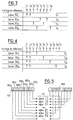
- FIG. 3 schematically represents four sequences of optical signals emitted respectively by four beacons 301, 302, 303, 304. Reference cycles have also been shown in FIG. 3 corresponding only to the moments of emission of the beacons. In the case of the invention, the duration of a reference cycle is fixed at 5 milliseconds but it is advantageously possible to provide for a shorter or longer reference cycle duration.
- the emitting beacons 301, 302, 303, 304 are synchronized with one another so that each emits a light pulse only at the instants corresponding to a reference cycle.
- a synchronization device 20 connected to each of said transmitting beacons observed simultaneously by a wired link for example, the synchronization device 20 generating the synchronization clock signal of the beacons of the impulse type for example, illustrated in FIG. 3.
- the synchronization device 20 generating the synchronization clock signal of the beacons of the impulse type for example, illustrated in FIG. 3.
- each beacon comprises an electronic unit (not shown) making it possible to control the opening time of its light emitter at each clock pulse delivered by the synchronization device 20 and corresponding to a reference cycle.
- the electronic unit receiving the pulses generates a train of light pulses characteristic for example of the identification number of a beacon or any other parameter used for its identification.
- This type of synchronization device is well known to those skilled in the art and will not be described.
- the optical signals emitted by the beacons are composed of sequences S1, S2, S3, S4 associated respectively with the beacons 301, 302, 303, 304, each sequence comprising eight reference cycles represented by the pulses referenced I1 to I8 of the reference clock.
- the time coding of the optical signals emitted by the beacons consists in assigning to each signal sequence S1 to S4, two pulses corresponding to two reference cycles. Furthermore, the time separating these two pulses characterizes the beacon emitting the corresponding signal.
- the beacon 301 emits light pulses corresponding to the pulses I1, I2.
- the beacon 302 emits light pulses corresponding to the pulses I5, I7.
- the beacon 303 emits light pulses corresponding to the pulses I3, I6 and the beacon 304 emits light pulses corresponding to the pulses I4, I8. It will be noted that according to this temporal distribution of the pulses I1 to I8, none of the four beacons simultaneously emits a light pulse.
- the eight reference cycles constitute an elementary observation time period of the observation device 40.
- the four beacons each emit a sequence of light coding pulses identifying them. It should be noted, however, that recognition of the codes of the beacons can only be carried out if during the observation time period there is a location making it possible to identify at least one pulse of a beacon with respect to the other pulses. This identification can be obtained simply by deleting one of the four tags so that the coding method as described will allow validly the simultaneous observation of three tags in an observation time period corresponding to eight reference cycles.
- an observation time period corresponding to seven reference cycles can be provided by removing, for example, tag 4 from the group of tags observed.
- An example of a coding method for three or four tags has been given. Of course, it is advantageously possible to increase the number of beacons observed simultaneously by increasing the observation time period.
- the observation device 40 detects at the level of the cell 41 a first light pulse I1 emitted by the beacon 301.
- the control and calculation circuit 43 is connected to a first time base 60 counting per reference cycle of 5 milliseconds previously adjusted as a function of the duration of the reference cycles of the synchronization device 20.
- the time base 60 supplies the circuit control and calculation 43 of clock ticks at each occurrence of a reference cycle.
- the circuit command and calculation 43 detects the pulse I1 and positions an information element for example the first binary element 1011, in state 1 in a current control word 100 placed in the memory 60 of the random access memory type for example.
- the current control word 100 in the case of a time coding over an observation time period of eight reference cycles, also comprises eight consecutive locations forming a word of eight binary elements.
- the control and calculation circuit 43 determines the measured angular data alpha 1.1 corresponding to the pulse I1 and the memories in a list 110 of angular data placed for example in memory 60 .
- the beacon 301 After the flow of a reference cycle from the instant of emission of the first pulse I1, the beacon 301 emits a second light pulse I2 which is detected by the observation device 40.
- the latter calculates the data corresponding angles and checks that the occurrence of the received light pulse corresponds to an occurrence of a reference cycle given by the time base 60 with a predetermined tolerance. in this way, the observation device 40 can check the coherence of the detected light pulses and in this case, the control and calculation circuit 43 stores the angular data alpha 1.2 measured in a second location of the list 110 and positions at 1 the second binary element 1002 of the current control word 100.
- the tag 303 After the completion of a reference cycle, the tag 303 emits a light pulse I3 which is detected by the observation device 40.
- the control and calculation circuit 43 After calculation of the angular data and verification of the consistency of the occurrence of the detected pulse, the control and calculation circuit 43 stores the angular data alpha 1.3 in the third location of the list 110 and positions the third binary element 1003 of the control word 100 at 1. After the completion of a reference cycle, the control and calculation circuit 43 does not detect any impulse because that the 304 tag has been deleted. The control and calculation circuit 43 having received no light pulse corresponding to the fourth reference cycle given by the time base 60 initializes the fourth location in the list of angular data 110 and positions the fourth binary element 1004 of the word at zero. current control 100. After a following reference cycle has elapsed, the observation device 40 detects a pulse I5 emitted by the beacon 302.
- the list 110 of data angular contains the angular data sequence alpha 1.1, alpha 1.2, alpha 3.1, -, alpha 2.1, alpha 3.2, alpha 2.2, -.
- alpha represents the angular data measured and the associated index corresponds to the tag number and to the number of the pulse emitted by the tag.
- the identification of the transmitting beacons and the association with the corresponding measured angular data is carried out as follows.
- the calculation control circuit 43 performs an identical search for the current control word 100 in a table 150 of control words previously recorded thanks to a suitable and easy-to-carry out search program.
- the control word table 150 contains all the possible binary combinations 1501, 1502, 1503 ... of the current control word 100 corresponding to a pulse time distribution for coding the light signals emitted by three beacons 301, 302, 303 , as shown in FIG. 6.
- This table of control words 150 can therefore contain in the present case up to 256 different control words but only eight of these are likely to correspond to the current control word 100.
- We associate with the control word table 150 a corresponding tag identification word table 250 previously recorded, each tag identification word 2001, 2002, 2003 ... corresponding to a control word 1501, 1502, 1503 ... respectively from the control word table 150.
- An information element of a control word 150 i of the control word table 150 is matched with a tag identification number of the tag identification word 200 of the tag identification word table. 250.
- the control and calculation circuit 43 obtains the control word 150 i after searching in the table 150 identical to the current control word 100 obtained after a period of observation time, it recovers from the table 250, the corresponding tag identification word 200 i using the same table index as is known to those skilled in the art.
- the control and calculation circuit 43 on the basis of the tag identification word 200 i obtained previously, associates with each element of the tag identification word 200 the angular data measured and stored in the form of a list 110 in the memory. 60, the association being made by identical index of the word identification tag 200 and the list of angular data 110.
- the identification number of the tag 301 is 1 in the identification word of the tag 200, 2 for the tag 302, 3 for the tag 303.
- the value of the index of the location of the tag identification number in the word 200 gives the value of the index in the list 110 so that the command and calculation circuit 43 will restore at the end of the period of observation time the pairs (1, alpha 1.1), (1, alpha 1.2), (3, alpha 3.1), (2, alpha 2.1), (3, alpha 3.2), (2, alpha 2.2).
- the coding of the light signals emitted by the beacons 30 is carried out by temporal distribution of the pulses within a coding sequence S′1, S′2, S′3, S′4 corresponding to an observation time period, each sequence comprising at least two synchronization pulses I1, I2 whose time difference corresponds to a first reference cycle d '' a duration of 2.5 milliseconds for example and a coding pulse I4, I6, I8, I10 for the identification of the transmitting beacon, the time difference between the coding pulse and the last synchronization pulse being characteristic of the tag, for example its identification number.
- the elementary reference cycles represented by the pulses I1 to I10 given by the synchronization device 20 are reported.
- the time difference between each reference cycle fixed at 2.5 milliseconds may be a different shorter or longer duration.
- the coding pulse I i associated with a tag 30 i is temporally offset from the second synchronization pulse I2 by a period of time multiple of the identification number i of the tag 30 i considered.
- the time difference between the second synchronization pulse I2 and the coding pulse I4 is 5 milliseconds expressed by 1 x 2 x time of a reference cycle where 1 represents the beacon number and 2 represents the multiple number arbitrarily fixed.
- the beacons observed simultaneously are synchronized with each other so that at each observation time period they simultaneously transmit the two synchronization pulses I1, I2, the coding pulses I4, I6, I8, I10 being transmitted at different times respectively by each of the tags 301, 302, 303, 30ises.
- the coding pulses I4, I6, I8, I10 being transmitted at different times respectively by each of the tags 301, 302, 303, 30ises.
- the beacons 301 ... 304 simultaneously emit a first pulse I1 which is detected at the level of the sensor 41.
- the observation device 40 previously configured for the coding described above, initializes the first time base 60 supplying the control and calculation of clock ticks every 2.5 milliseconds.
- the control and calculation circuit 43 waits for the second synchronization pulse to occur on the next reference cycle.
- the beacons 301, 304 emit a second light pulse I2 which is detected by the observation device.
- the control and calculation circuit 43 checks that the occurrence of this pulse corresponds to a reference cycle, which makes it possible to ignore parasitic light pulses.
- the control and calculation circuit 43 triggers a second time base 70 counting per double reference cycle, for example 5 milliseconds.
- the second time base 70 can be replaced by the first time base 60 as soon as the control and calculation circuit takes into account a clock top out of two of the latter thanks to a program adapted easily achievable.
- the light pulse I4 is then emitted by the beacon 301 after two elementary reference cycles of 2.5 milliseconds, therefore a reference cycle of the time base 70.
- the time difference expressed in reference cycle of the time base 70 between the second synchronization pulse I2 and each of the coding pulses I4, I6, I8, I10 respectively associated with each of the beacons observed has been previously stored in memory 80 connected to the control and calculation circuit 43.
- the calculation control circuit 43 determines the number of reference cycle counting of the time base 70. In the present case, this number is 1. The control circuit and calculation 43 from the number of counts obtained identifies it as a tag number corresponding to the tag 301, determines the angular data corresponding to this light pulse and provides the pair tag identification number, measured angular data.
- This decoding process is similar for the other tags 302, 303, 30ises and will therefore not be described. The whole of the procedure described above is repeated as soon as the observation time period has elapsed after ten elementary reference cycles given by the first time base 60.
- This method of coding the optical signals of the beacons and of decoding signals by the observation device has the advantage of allowing recognition of the beacon upon reception of the coding pulse without prior search in prerecorded data tables.
- the control and calculation circuit 43 groups together the angular data associated with the same tag in the form of pairs (alpha 1.1, alpha 1.2), (alpha 2.1, alpha 2.2), (alpha 3.1, alpha 3.2) to compare the elements of each couple. This comparison will make it possible to determine the difference between the values of the angular data measured for a beacon at different times.
- the control and calculation circuit 43 will consider that these measured data are erroneous, for example if alpha 1.1 differs from alpha 1.2 by a deviation value greater than the value of predetermined deviation, the angular data corresponding to the tag 301 for example are considered to be invalid and the tag 301 is deemed invisible to the observation device until the next measurement of angular data. This comparison thus serves as security in addition to the control of the time separating two detected light pulses.
- the association two by two of the angular data measured during a period of observation time is also used for the identification of the transmitting beacons in the case where the four beacons 301, 302, 303, 304 are used simultaneously, each transmitting two coding pulses for example in a sequence comprising 8 reference cycles.
- the identification of the beacons is carried out by determining the "virtual" distance between the angular data likely to belong to the same beacon (angular data substantially identical to within a deviation). By establishing a correspondence virtual distance, number of transmitting beacon, one can easily allot a couple of angular data to a beacon reference.
- the distance between alpha 1.1 and alpha 1.2 in the table of angular data 110 is 1, which corresponds to the tag 301.
- the distance between alpha 2.1 and alpha 2.2 is 2 which corresponds to the 302 tag.
- the same is done for the 303 tag and the 304 tag which is not shown. In this way we make the most of the temporal space of the observation time period by using four transmitting beacons simultaneously. It will be noted that this method is compatible with the methods described above.
- Another variant of the tag position evaluation method consists in averaging the value of the measured angular data corresponding to a tag. This average can easily be achieved by the control and calculation circuit 43 under the control of an adapted program. After an observation time period, the control and calculation circuit 43 associates with a tag identification number an average value of angular data corresponding to an average position of the tag observed during the time period of observation.
- the invention finds numerous applications for the positioning of an object in space and the analysis of its orientation. It is possible, for example, to place on the object three beacons 30 in a triangular arrangement and to observe these beacons thus arranged by two identical observation devices 40.
- the arrangement of the system makes it possible, by a triangulation calculation method from the information delivered by each of the control and calculation circuits 43 of each observation device, to determine the geometric characteristics of the location of the beacons on the object, the position in space of the object and the orientation of its axes relative to the frames of reference constituted by the optical axes of the two observation devices and their reference plane.
- the observation device 40 is placed on an object that is movable relative to a fixed frame of reference represented by a group of tags (3 or 4 tags).
- a group of tags (3 or 4 tags).
- the observation device detects in its field of view a group of three synchronous beacons, it calculates the position of each of them relative to its axis of observation, then the interbalanced angles as is known to those skilled in the art. He then deduces by knowing the distance separating two beacons, its position in the plane relative to these beacons and its orientation on itself in this plane.
- a fourth tag makes it possible to calculate the position of the mobile object in the plane and its orientation along the axis normal to the plane.
- the use of several groups of synchronous beacons allows a mobile machine to position itself during its evolution relative to the closest group of beacons it can meet.
Description
Le domaine de l'invention est celui de la localisation et du repérage de machines ou objets mobiles, par des appareils d'observation destinés à fournir les coordonnées angulaires d'un ou plusieurs points de ces machines ou objets mobiles matérialisé par exemple, par un ou plusieurs émetteurs de signaux optiques appelés balises, les coordonnées angulaires étant évaluées par rapport à l'axe d'observation de l'appareil.The field of the invention is that of locating and locating machines or mobile objects, by observation devices intended to provide the angular coordinates of one or more points of these machines or mobile objects materialized for example, by a or several transmitters of optical signals called beacons, the angular coordinates being evaluated with respect to the observation axis of the device.
Plus spécifiquement, l'invention concerne un nouveau procédé d'évaluation simultané des positions relatives d'une pluralité de balises par rapport à un référentiel constitué par l'axe optique d'un dispositif d'observation, chaque balise émettrice émettant un signal optique du type impulsionnel codé temporellement et spécifique de la balise, ledit dispositif d'observation détectant dans son champ d'observation les signaux codés desdites balises émettrices pour fournir des donnés angulaires correspondant respectivement aux angles définis par le dispositif d'observation et les balises.More specifically, the invention relates to a new method for the simultaneous evaluation of the relative positions of a plurality of beacons relative to a frame of reference constituted by the optical axis of an observation device, each transmitting beacon emitting an optical signal from the pulse type temporally coded and specific to the beacon, said observation device detecting in its field of observation the coded signals of said transmitting beacons to supply angular data corresponding respectively to the angles defined by the observation device and the beacons.
Le document PCT WO87/07009 divulgue un système de localisation de position pour un robot mobile qui inclut un détecteur multisecteur capable de détecter un signal codé émis par une balise placée à distance du robot. Ce système connu permet notamment de définir la position du robot mobile par rapport à une balise spécifique parmi un nombre de balises identifiables séparément en fournissant des données angulaires entre la balise observée et le robot.PCT document WO87 / 07009 discloses a position location system for a mobile robot which includes a multi-sector detector capable of detecting a coded signal emitted by a beacon placed at a distance from the robot. This known system makes it possible in particular to define the position of the mobile robot relative to a specific beacon from a number of beacons identifiable separately by providing angular data between the observed beacon and the robot.
Dans ce système, chaque balise est autonome. L'identification de la balise se fait par la détection des transitions du signal codé au moyen d'un circuit différentiateur. Chaque balise émet une séquence lumineuse toutes les 15,6 millisecondes. Chaque séquence lumineuse comprend une combinaison binaire d'impulsions de codage de façon à pouvoir identifier 128 balises différentes.In this system, each tag is autonomous. The beacon is identified by detecting the transitions of the coded signal by means of a differentiating circuit. Each beacon emits a light sequence every 15.6 milliseconds. Each light sequence includes a binary combination coding pulses so that 128 different tags can be identified.
Cependant, dans ce système connu on procède à un repérage balise par balise du fait que le codage des signaux lumineux impose au détecteur de position d'observer une balise à la fois. Ainsi pour observer une pluralité de balises simultanément il est nécessaire de disposer d'une pluralité de détecteurs de position associés à une pluralité de balises.However, in this known system, a tag-by-tag tracking is carried out because the coding of the light signals requires the position detector to observe one tag at a time. Thus to observe a plurality of beacons simultaneously it is necessary to have a plurality of position detectors associated with a plurality of beacons.
Ce système connu ne permet donc pas une observation globale d'une pluralité de balises émettant dans le champ d'observation d'un seul détecteur de position.This known system therefore does not allow an overall observation of a plurality of beacons emitting in the observation field of a single position detector.
Le brevet US-A-40 81 669 divulgue un système de reconnaissance pour un robot qui détecte une information codée sous forme de signal optique provenant d'une balise émettrice permettant au robot de reconnaître et d'identifier la source d'émission ou balise.US-A-40 81 669 discloses a recognition system for a robot which detects coded information in the form of an optical signal coming from a transmitting beacon allowing the robot to recognize and identify the emission source or beacon.
Le signal optique est décodé et est comparé avec une information mémorisée dans le robot pour fournir l'identification de la source émettrice. Le codage des signaux optiques émis par une source consiste à transmettre des impulsions de signaux optiques représentant les bits d'un mot de code correspondant à la représentation binaire d'un numéro d'identification de la source. Dans ce brevet, le système de reconnaissance ne peut détecter qu'une source à la fois.The optical signal is decoded and compared with information stored in the robot to provide identification of the transmitting source. The coding of the optical signals emitted by a source consists in transmitting pulses of optical signals representing the bits of a code word corresponding to the binary representation of an identification number of the source. In this patent, the recognition system can only detect one source at a time.
Le procédé de codage des signaux optiques des sources et le dispositif d'observation divulgués dans ces deux documents ne sont pas adaptés pour l'évaluation simultanée des positions d'une pluralité de balises émettrices.The method for coding the optical signals of the sources and the observation device disclosed in these two documents are not suitable for the simultaneous evaluation of the positions of a plurality of transmitting beacons.
Dans ces systèmes connus, le repérage de plusieurs balises se fait donc successivement en dirigeant le dispositif d'observation ou capteur par le jeu d'un système mécanique ou électromécanique en direction de la balise à observer. L'inconvénient de l'utilisation de tels systèmes mécaniques réside essentiellement dans leur temps de réaction relativement lent par rapport au temps de détection d'une balise.In these known systems, the location of several beacons is therefore done successively by directing the observation device or sensor by the play of a mechanical or electromechanical system in the direction of the beacon to be observed. The drawback of using such mechanical systems essentially lies in their relatively slow reaction time compared to the time for detecting a beacon.
Par ailleurs, dans les dispositifs connus, les balises émettrices doivent être espacées d'une distance suffisante pour garantir qu'elles ne soient pas observées simultanément du fait des problèmes de brouillage des signaux, les balises fonctionnant de manière asynchrone. Ces dispositifs connus sont donc limités dans leur utilisation notamment au niveau de la largeur de champ d'observation du dispositif d'observation.Furthermore, in known devices, the transmitting beacons must be spaced apart by a sufficient distance to guarantee that they are not observed simultaneously due to problems of signal interference, the beacons operating asynchronously. These known devices are therefore limited in their use, in particular at the level of the observation field width of the observation device.
On connaît également, par l'article "Design in practice : AVG's gain their freedom", paru dans la revue ENGINEERING, volume 228, N° 8, septembre 1988, page 393, un procédé d'évaluation des positions relatives d'une pluralité de balises dans un système de localisation de balises dans lequel les balises codées émettent des impulsions lumineuses et un dispositif d'observation détecte l'impulsion d'une balise et fournit sa position angulaire.We also know, by the article "Design in practice: AVG's gain their freedom", published in the journal ENGINEERING, volume 228, N ° 8, September 1988, page 393, a method of evaluating the relative positions of a plurality beacons in a beacon location system in which the coded beacons emit light pulses and an observation device detects the beacon pulse and provides its angular position.
En conséquence l'objectif de l'invention est de palier à ces différents inconvénients de la technique en proposant un nouveau procédé d'évaluation simultanée des positions relatives d'une pluralité de balises rapport à un référentiel constitué par l'axe optique d'un dispositif d'observation, chaque balise émettant un signal optique du type impulsionnel, codé temporellement et spécifique de la balise, ledit dispositif d'observation détectant dans son champ d'observation les signaux codés desdites balises émettrices pour fournir des données angulaires correspondant respectivement aux angles définis par le dispositif d'observation et les balises.Consequently, the objective of the invention is to overcome these various drawbacks of the technique by proposing a new method for the simultaneous evaluation of the relative positions of a plurality of beacons relative to a frame of reference constituted by the optical axis of a observation device, each beacon emitting an optical signal of the impulse type, coded in time and specific for the beacon, said observation device detecting in its field of observation the coded signals of said emitting beacons to supply angular data corresponding respectively to the angles defined by the observation device and the beacons.
L'invention a donc pour objet un procédé d'évaluation des positions relatives d'une pluralité de balises dans un système de localisation de balises comprenant des balises codées émettant des impulsions lumineuses et un dispositif d'observation pour détecter un impulsion lumineuse d'une balise et fournir des données angulaires de positions de la balise par rapport au dispositif d'observation en réponse à ladite détection, caractérisé en ce qu'il comprend les étapes suivantes:
on fixe une période d'observation des balises comprenant un nombre prédéterminé de cycles de détection d'une impulsion lumineuse par le dispositif d'observation;
on synchronise les balises entre elles pour qu'elles émettent à tour de rôle, pendant la période d'observation, au moins deux impulsions lumineuses sur deux cycles de détection, de ladite periode d'observation en fonction d'une répartition temporelle préétablie des instants d'émission des impulsions lumineuses affectés à chaque balise;
on mémorise dans le dispositif d'observation ladite répartition temporelle pour associer à un cycle de détection une référence de balise particulière;
on initialise dans le dispositif d'observation une première base de temps comptant par cycle de détection à partir d'une première impulsion lumineuse détectée pour détecter l'occurrence des impulsions lumineuses pendant la période d'observation;
on mémorise à chaque impulsion détectée pendant la période d'observation, les données angulaires de la balise correspondant à ladite impulsion lumineuse par rapport au dispositif d'observation;
on affecte aux données angulaires mémorisées la référence de la balise particulière correspondant à ces données en associant l'ordre des occurences d'impulsions lumineuses détectées et ladite répartition temporelle mémorisée pour évaluer, pendant la période d'observation, la position des balises observées simultanément dans le champ d'observation du dispositif d'observation.The subject of the invention is therefore a method for evaluating the relative positions of a plurality of beacons in a beacon location system comprising coded beacons emitting light pulses and an observation device for detecting a light pulse from a beacon and provide angular data of positions of the beacon relative to the observation device in response to said detection, characterized in that it comprises the following steps:
a beacon observation period is set comprising a predetermined number of cycles of detection of a light pulse by the observation device;
the beacons are synchronized with each other so that they emit in turn, during the observation period, at least two light pulses over two detection cycles, of said observation period as a function of a pre-established time distribution of the instants emission of the light pulses assigned to each beacon;
said time distribution is stored in the observation device in order to associate a particular beacon reference with a detection cycle;
a first time base counting per detection cycle is initialized in the observation device from a first detected light pulse to detect the occurrence of the light pulses during the observation period;
is stored at each pulse detected during the observation period, the angular data of the beacon corresponding to said light pulse relative to the observation device;
the angular data stored is assigned the reference of the particular beacon corresponding to this data by associating the order of occurrences of detected light pulses and said stored time distribution in order to evaluate, during the observation period, the position of the beacons observed simultaneously in the field of observation of the observation device.
La répartition temporelle des impulsions de codage à l'intérieur d'une période de temps d'observation divisée en cycles de référence et combinée au synchronisme de l'émission des signaux des balises permet de faire émettre simultanément à l'intérieur de la période de temps d'observation une pluralité de balises sans craindre des phénomènes d'interférence de signaux. De cette manière, le dispositif d'observation peut observer la pluralité de balises sans s'orienter vers l'une ou l'autre des balises, puisqu'il ne reçoit qu'une impulsion de codage à la fois. Le dispositif d'observation est synchronisé sur les émissions optiques des balises, et par la première base de temps il contrôle le temps séparant les impulsions des balises. De cette manière, il est possible de contrôler si l'impulsion de lumière reçue par le dispositif d'observation correspond bien à un signal émis par une balise. A chaque détection d'une impulsion, le dispositif d'observation mesure des données angulaires correspondant à la position de la balise émettrice. L'association d'une balise identifiée avec les données angulaires lui correspondant est réalisée facilement dès lors que l'on connaît la répartition temporelle des impulsions détectées donnée par la base de temps.The temporal distribution of the coding pulses within an observation time period divided into reference cycles and combined with the synchronism of the transmission of the beacon signals makes it possible to transmit simultaneously within the period of observation time a plurality of beacons without fear of signal interference phenomena. In this way, the observation device can observe the plurality of beacons without orienting itself towards one or the other of the beacons, since it receives only one coding pulse at a time. The observation device is synchronized with the optical transmissions of the beacons, and by the first time base it controls the time separating the pulses from the beacons. In this way, it is possible to check whether the light pulse received by the observation device corresponds to a signal emitted by a beacon. Each time a pulse is detected, the observation device measures angular data corresponding to the position of the transmitting beacon. The association of an identified tag with the corresponding angular data is easily carried out as soon as we know the temporal distribution of the detected pulses given by the time base.
Selon une autre caractéristiques de l'invention la répartition temporelle des impulsions des signaux optiques codés à l'intérieur d'une période de temps d'observation est telle que chaque signal optique du type impulsionnel est composé d'une séquence d'une durée égale à la période de temps d'observation, ladite séquence comprenant deux impulsions dont l'écart temporel à l'intérieur de la période de temps d'observation est caractéristique de la balise émettrice du signal, les impulsions de l'ensemble des signaux optiques codés émis par la pluralité de balises observées ne se recouvrant pas temporellement à l'intérieur d'une période de temps d'observation.According to another characteristic of the invention, the temporal distribution of the pulses of the optical signals coded within an observation time period is such that each optical signal of the pulse type is composed of a sequence of equal duration. during the observation time period, said sequence comprising two pulses whose time difference within the observation time period is characteristic of the signal transmitter, the pulses of all of the coded optical signals emitted by the plurality of observed beacons not overlapping in time within an observation time period.
Selon encore une autre caractéristique de l'invention, l'étape de mémorisation des données angulaires comprend en outre
une étape de positionnement d'un élément d'information dans un emplacement d'un mot de contrôle courant comportant un nombre prédéterminé d'emplacements, parallèlement à la mémorisation d'une donnée angulaire mesurée, la position de l'emplacement dans le mot de contrôle étant déterminée par le numéro de comptage de cycles de référence de la première base de temps,
et dans lequel l'analyse de la répartition temporelle des impulsions de signaux codés à l'intérieur de la période de temps d'observation comprend
une recherche à l'identique du mot de contrôle courant dans une table de mots de contrôle préenregistrés, chaque mot de contrôle préenregistré étant associé à un mot d'identification de balises émettrices, l'association du mot d'identification de balises émettrices et de la succession de données angulaires mémorisées donnant pour chaque balise identifiée les données angulaires correspondantes mesurées pendant la période de temps d'observation.According to yet another characteristic of the invention, the step of memorizing the angular data further comprises
a step of positioning an item of information in a location of a current control word comprising a predetermined number of locations, parallel to the memorization of a measured angular datum, the position of the location in the control being determined by the counting number of reference cycles of the first time base,
and wherein the analysis of the time distribution of the coded signal pulses within the observation time period includes
an identical search for the current control word in a table of prerecorded control words, each prerecorded control word being associated with a word for identifying beacons, the association of the word for identifying beacons and the succession of stored angular data giving for each identified beacon the corresponding angular data measured during the observation time period.
Ainsi, à chaque impulsion de signal détectée par le dispositif d'observation, on détermine la position de la balise émettrice ce qui permet le suivi précis d'objets en mouvement rapide par exemple. Cependant la détermination de la balise émettrice et son association avec les données angulaires mesurées lui correspondant n'a lieu qu'à la fin de la période d'observation.Thus, at each signal pulse detected by the observation device, the position of the transmitting beacon is determined, which allows precise tracking of objects in rapid movement for example. However, the determination of the transmitting beacon and its association with the corresponding measured angular data takes place only at the end of the observation period.
Selon encore une autre caractéristique de l'invention la répartition temporelle des impulsions des signaux optiques codés à l'intérieur d'une période de temps d'observation est telle que chaque signal optique du type impulsionnel est composé d'une séquence d'une durée égale à la période d'observation, ladite séquence comprenant deux impulsions de synchronisation suivies d'une troisième impulsion décalée temporellement des deux impulsions de synchronisation d'un intervalle de temps proportionnel à un numéro d'identification d'une balise.According to yet another characteristic of the invention, the temporal distribution of the pulses of the optical signals coded within an observation time period is such that each optical signal of the pulse type is composed of a sequence of duration equal to the observation period, said sequence comprising two synchronization pulses followed by a third pulse temporally offset from the two synchronization pulses by a time interval proportional to an identification number of a beacon.
Selon encore une autre caractéristique de l'invention l'étape de mémorisation des données angulaires comprend en outre
une étape d'initialisation d'une seconde base de temps comptant par cycle de référence, lors de la détection de la dernière impulsion de synchronisation des signaux codés émis par la pluralité de balises,
une étape de reconnaissance d'une impulsion décalée précédent la mémorisation d'une donnée angulaire mesurée et correspondant à l'occurrence d'un comptage de multiples de cycles de référence par la seconde base de temps
et dans lequel l'analyse de la répartition temporelle des impulsions de signaux codés à l'intérieur de la période de temps d'observation étant effectuées en associant le nombre multiple de cycle de référence écoulé entre la dernière impulsion de synchronisation et l'impulsion de signal décalée et le numéro d'identification prédéterminé de la balise émettrice de l'impulsion de signal décalée.According to yet another characteristic of the invention, the step of memorizing the angular data further comprises
a step of initializing a second time base counting per reference cycle, upon detection of the last synchronization pulse of the coded signals transmitted by the plurality of beacons,
a step of recognizing an offset pulse preceding the memorization of a measured angular datum and corresponding to the occurrence of a counting multiples of reference cycles by the second time base
and wherein the analysis of the temporal distribution of the coded signal pulses within the observation time period being performed by associating the multiple number of reference cycles elapsed between the last synchronization pulse and the shifted signal and the predetermined identification number of the beacon transmitting the shifted signal pulse.
Grâce au fait que le décalage temporel de l'impulsion de codage par rapport aux impulsions de synchronisation est proportionnel à un numéro d'identification de balise, chaque balise émettrice d'une impulsion décalée est reconnue immédiatement par consultation de la seconde base de temps sans attendre l'échéance de la période d'observation.By virtue of the fact that the time offset of the coding pulse with respect to the synchronization pulses is proportional to a tag identification number, each tag transmitting a shifted pulse is recognized immediately by consulting the second time base without wait for the end of the observation period.
Selon encore une autre caractéristique de l'invention, on compare les données angulaires mesurées pendant une période de temps d'observation et associées à une balise par rapport à une valeur d'écart prédéterminée.According to yet another characteristic of the invention, the angular data measured during a period of observation time and associated with a beacon are compared with respect to a predetermined deviation value.
De cette manière on vérifie que les impulsions lumineuses reçues correspondent bien à une configuration possible de la répartition temporelle des impulsions de codage.In this way, it is verified that the light pulses received correspond to a possible configuration of the time distribution of the coding pulses.
Selon une autre caractéristique de l'invention on effectue le calcul de données angulaires moyennes à partir des données angulaires mesurées pendant la période de temps d'observation et associées à une balise.According to another characteristic of the invention, the average angular data is calculated from the angular data measured during the observation time period and associated with a beacon.
De cette manière on obtient une position moyenne de chaque balise après chaque période de temps d'observation ce qui permet de suivre des balises animées d'un mouvement rapide.In this way, an average position of each beacon is obtained after each observation time period, which makes it possible to follow beacons animated with a rapid movement.
D'autres caractéristiques et avantages de l'invention ressortiront mieux encore de la description qui va suivre concernant une forme de réalisation préférentielle de l'invention donnée à titre d'exemple non limitatif et illustrée sur les dessins ci-joints dans lesquels :
- la figure 1 représente de façon schématique un dispositif d'observation associé à une pluralité de balises,
- la figure 2 représente de façon schématique un dispositif d'observation de balises,
- la figure 3 représente un diagramme des temps concernant une première répartition temporelle des impulsions de signaux émis par les balises selon l'invention,
- la figure 4 représente un diagramme des temps concernant une seconde répartition temporelle des impulsions de signaux émis par les balises selon l'invention,
- la figure 5 représente un mot de contrôle, une liste de données angulaires et un mot d'identification de balises selon l'invention,
- la figure 6 représente une table de mots de contrôle associée à une table de mots d'identification de balises.
- FIG. 1 schematically represents an observation device associated with a plurality of beacons,
- FIG. 2 schematically represents a device for observing beacons,
- FIG. 3 represents a time diagram relating to a first temporal distribution of the signal pulses emitted by the beacons according to the invention,
- FIG. 4 represents a time diagram relating to a second temporal distribution of the signal pulses emitted by the beacons according to the invention,
- FIG. 5 represents a control word, a list of angular data and a tag identification word according to the invention,
- FIG. 6 represents a table of control words associated with a table of tag identification words.
Comme visible sur la figure 1, le dispositif d'observation 40 est placé à distance d'une pluralité de balises 30, une balise pouvant représenter par exemple un point d'un objet ou l'objet lui-même. Chaque balise 30 émet un signal optique, par exemple un signal lumineux infrarouge de longueur d'onde prédéterminée (880 nm ou 940nm), l'émission lumineuse se faisant sous forme pulsée et codée par répartition temporelle des impulsions de signal lumineux, la répartition temporelle des impulsions lumineuses étant caractéristique de la balise, de l'objet ou de la partie de l'objet auquel elle est associée. De façon générale, selon l'invention, toute source capable d'émettre un signal détectable et décodable peut être utilisée avantageusement. Cependant dans la description, nous nous limiterons à un signal lumineux infrarouge couramment utilisé dans le domaine technique de l'invention.As visible in FIG. 1, the
Selon la figure 2, le dispositif d'observation 40 ou caméra est principalement composé d'une cellule de détection de position 41 reliée à un circuit électronique 42 chargé notamment du traitement des signaux électriques issus de la cellule 41. De façon connue, la cellule 41 se compose par exemple d'une surface de silicium photosensible ou tout autre matériau équivalent, coopérant avec des connecteurs de courant latéral (non représentés). La cellule de détection recevant un impact lumineux, par exemple une impulsion lumineuse, restitue quatre composantes de courant détectées respectivement par les quatre connecteurs, la valeur des composantes de courant étant proportionnelle à l'intensité lumineuse globale reçue et fonction de la position de l'impact lumineux sur la surface de silicium de la cellule 41.According to FIG. 2, the
Les circuits électroniques 42, à partir des composants de courant latéral mesurés déterminent par calcul des données angulaires de position de la source de l'impulsion lumineuse reçue par rapport au dispositif d'observation 40. Les données angulaires peuvent notamment correspondre à des données de site et d'azimut déterminées par rapport à l'axe optique 50 du dispositif d'observation assimilé à un référentiel. Pour le calcul des données angulaires, il est courant d'utiliser des moyens de calcul et de commande 43 reliés au circuit électronique 42, les moyens de calcul et de commande pouvant notamment être du type microprocesseur.The
Selon l'invention, le dispositif d'observation 40 observe simultanément une pluralité de balises, c'est-à-dire qu'il reçoit pendant une période de temps d'observation prédéterminée, une pluralité de signaux infrarouges provenant respectivement d'une pluralité de balises émettrices. Pour ce faire, l'invention prévoit que les signaux optiques émis par les balises 30 sont du type signaux impulsionnels, les impulsions étant réparties temporellement dans la période de temps d'observation, et les balises 30 étant synchronisées entre elles de manière à éviter tout phénomène de recouvrement de signaux entre les balises émettrices.According to the invention, the
La figure 3 représente de façon schématique quatre séquences de signaux optiques émises respectivement par quatre balises 30₁, 30₂, 30₃, 30₄. On a fait figurer aussi sur la figure 3 des cycles de référence correspondants aux seuls instants d'émission des balises. Dans le cas de l'invention, la durée d'un cycle de référence est fixée à 5 millisecondes mais on pourra avantageusement prévoir une durée de cycle de référence plus courte ou plus longue.FIG. 3 schematically represents four sequences of optical signals emitted respectively by four
Les balises émettrices 30₁, 30₂, 30₃, 30₄ sont synchronisées entre elles de façon que chacune émette une impulsion lumineuse seulement aux instants correspondant à un cycle de référence. Selon un mode de réalisation de l'invention, on prévoit un dispositif de synchronisation 20 relié à chacune desdites balises émettrices observées simultanément par une liaison filaire par exemple, le dispositif de synchronisation 20 engendrant le signal d'horloge de synchronisation des balises du type impulsionnel par exemple, illustré en figure 3. On pourra prévoir avantageusement qu'une des balises observées se conduise en maître par rapport aux autres balises de façon que cette balise maître remplace le dispositif de synchronisation 20. Dans le cas de l'utilisation d'un dispositif de synchronisation 20, chaque balise comporte un boîtier électronique (non représenté) permettant de commander le temps d'ouverture de son émetteur de lumière à chaque impulsion d'horloge délivrée par le dispositif de synchronisation 20 et correspondant à un cycle de référence.The emitting
Le boîtier électronique recevant les impulsions engendre un train d'impulsions lumineuses caractéristique par exemple du numéro d'identification d'une balise ou de tout autre paramètre servant à son identification. Ce type de dispositif de synchronisation est bien connu de l'homme de l'art et ne fera pas l'objet d'une description.The electronic unit receiving the pulses generates a train of light pulses characteristic for example of the identification number of a beacon or any other parameter used for its identification. This type of synchronization device is well known to those skilled in the art and will not be described.
Comme visible sur la figure 3, selon un premier mode de réalisation de l'invention, les signaux optiques émis par les balises sont composés de séquences S1, S2, S3, S4 associées respectivement aux balises 30₁, 30₂, 30₃, 30₄, chaque séquence comprenant huit cycles de référence représentés par les impulsions référencées I1 à I8 de l'horloge de référence. le codage temporel des signaux optiques émis par les balises consiste à affecter à chaque séquence de signal S1 à S4, deux impulsions correspondant à deux cycles de référence. Par ailleurs, le temps séparant ces deux impulsions caractérise la balise émettrice du signal correspondant. Ainsi la balise 30₁ émet des impulsions lumineuses correspondant aux impulsions I1, I2. La balise 30₂ émet des impulsions lumineuses correspondant aux impulsions I5, I7. La balise 30₃ émet des impulsions lumineuses correspondant aux impulsions I3, I6 et la balise 30₄ émet des impulsions lumineuses correspondant aux impulsions I4, I8. On remarquera que selon cette répartition temporelle des impulsions I1 à I8, aucune des quatre balises émet simultanément une impulsion lumineuse.As visible in FIG. 3, according to a first embodiment of the invention, the optical signals emitted by the beacons are composed of sequences S1, S2, S3, S4 associated respectively with the
Les huit cycles de référence constituent une période de temps d'observation élémentaire du dispositif d'observation 40. Pendant cette période de temps d'observation, les quatre balises émettent chacune une séquence d'impulsion lumineuse de codage les identifiant. On notera toutefois que la reconnaissance des codes des balises ne pourra être réalisée que s'il existe pendant la période de temps d'observation un repérage permettant d'identifier au moins une impulsion d'une balise par rapport aux autres impulsions. Ce repérage peut être obtenue simplement en supprimant une des quatre balises de sorte que le procédé de codage tel que décrit permettra valablement l'observation simultanée de trois balises dans une période de temps d'observation correspondant à huit cycles de référence. Bien entendu, on pourra prévoir une période de temps d'observation correspondant à sept cycles de référence en supprimant par exemple la balise 4 du groupe de balises observées. On a donné un exemple de procédé de codage pour trois ou quatre balises. Bien entendu on pourra avantageusement augmenter le nombre de balises observées simultanément en augmentant la période de temps d'observation.The eight reference cycles constitute an elementary observation time period of the
Nous allons maintenant décrire le fonctionnement du dispositif d'observation 40 relativement au procédé de codage ci-dessus décrit.We will now describe the operation of the
Le dispositif d'observation 40 détecte au niveau de la cellule 41 une première impulsion lumineuse I1 émise par la balise 30₁. Le circuit de commande et de calcul 43 est relié à une première base de temps 60 comptant par cycle de référence de 5 millisecondes préalablement réglée en fonction de la durée des cycles de référence du dispositif de synchronisation 20. La base de temps 60 fournit au circuit de commande et de calcul 43 des tops d'horloge à chaque occurrence d'un cycle de référence. Le circuit de commande et de calcul 43 détecte l'impulsion I1 et positionne un élément d'information par exemple le premier élément binaire 101₁, à l'état 1 dans un mot de contrôle courant 100 placé dans la mémoire 60 de type mémoire vive par exemple. Le mot de contrôle courant 100 dans le cas d'un codage temporel sur une période de temps d'observation de huit cycles de référence, comporte également huit emplacements consécutifs formant un mot de huit éléments binaires. Après la mise à jour du mot de contrôle courant 100, le circuit de commande et de calcul 43 détermine les données angulaires mesurées alpha 1.1 correspondant à l'impulsion I1 et les mémoires dans une liste 110 de données angulaires placée par exemple dans la mémoire 60.The
Après l'écoulement d'un cycle de référence à partir de l'instant d'émission de la première impulsion I1, la balise 30₁ émet une deuxième impulsion lumineuse I2 laquelle est détectée par le dispositif d'observation 40. Ce dernier calcule les données angulaires correspondantes et contrôle que l'occurrence de l'impulsion lumineuse reçue correspond à une occurrence d'un cycle de référence donnée par la base de temps 60 avec une tolérance prédéterminée. de cette manière, le dispositif d'observation 40 peut vérifier la cohérence des impulsions lumineuses détectées et dans ce cas, le circuit de commande et de calcul 43 mémorise les données angulaires alpha 1.2 mesurées dans un second emplacement de la liste 110 et positionne à 1 le second élément binaire 100₂ du mot de contrôle courant 100. Après écoulement d'un cycle de référence, la balise 30₃ émet une impulsion lumineuse I3 qui est détectée par le dispositif d'observation 40. Après calcul des données angulaires et vérification de la cohérence de l'occurrence de l'impulsion détectée, le circuit de commande et de calcul 43 mémorise les données angulaires alpha 1.3 dans le troisième emplacement de la liste 110 et positionne à 1 le troisième élément binaire 100₃ du mot de contrôle 100. Après écoulement d'un cycle de référence, le circuit de commande et de calcul 43 ne détecte aucune impulsion du fait que la balise 30₄ a été supprimée. Le circuit de commande et de calcul 43 n'ayant reçu aucune impulsion lumineuse correspondant au quatrième cycle de référence donné par la base de temps 60 initialise le quatrième emplacement de la liste des données angulaires 110 et positionne à zéro le quatrième élément binaire 100₄ du mot de contrôle courant 100. Après écoulement d'un cycle de référence suivant, le dispositif d'observation 40 détecte une impulsion I5 émis par la balise 30₂. Il met à jour la liste de données angulaires 110 et le mot de contrôle courant 100 de façon identique au cas précédemment décrit. Le traitement se poursuit de manière similaire jusqu'au huitième cycle de référence représenté par l'impulsion I8 pour obtenir un mot de contrôle courant 100 représenté en figure 5 dont le contenu est 0 1 1 1 0 1 1 1. La liste 110 de données angulaires contient la suite de données angulaires alpha 1.1, alpha 1.2, alpha 3.1,-, alpha 2.1, alpha 3.2, alpha 2.2, -. Dans cette liste 110, alpha représente les données angulaires mesurées et l'indice associé correspond au numéro de balise et au numéro de l'impulsion émise par la balise. Lorsque les données angulaires n'ont pas été mesurées lors de l'occurrence d'un cycle de référence, l'emplacement de la liste est laissé a un état d'initialisation représenté par le symbole -.After the flow of a reference cycle from the instant of emission of the first pulse I1, the
L'identification des balises émettrices et l'association avec les données angulaires mesurées leur correspondant est effectuée de la manière suivante. Le circuit de commande de calcul 43 procède à une recherche à l'identique du mot de contrôle courant 100 dans une table 150 de mots de contrôle préalablement enregistrés grâce à un programme de recherche adapté et facile à réaliser. La table de mots de contrôle 150 contient toutes les combinaisons binaires possibles 150₁, 150₂, 150₃... du mot de contrôle courant 100 correspondant à une répartition temporelle d'impulsion pour le codage des signaux lumineux émis par trois balises 30₁, 30₂, 30₃, comme visible en figure 6. Cette table de mots de contrôle 150 peut donc contenir dans le cas présent jusqu'à 256 mots de contrôle différents mais seulement huit de ceux-ci sont susceptibles de correspondre au mot de contrôle courant 100. On associe à la table de mots de contrôle 150 une table de mots d'identification de balises 250 préalablement enregistrées correspondante, chaque mot d'identification de balise 200₁, 200₂, 200₃... correspondant à un mot de contrôle 150₁, 150₂, 150₃... respectivement de la table de mots de contrôle 150.The identification of the transmitting beacons and the association with the corresponding measured angular data is carried out as follows. The
On fait correspondre à un élément d'information d'un mot de contrôle 150i de la table de mots de contrôle 150 un numéro d'identification de balise du mot d'identification de balise 200 de la table de mots d'identification de balise 250. Ainsi lorsque le circuit de commande et de calcul 43 obtient le mot de contrôle 150i après recherche dans la table 150 identique au mot de contrôle courant 100 obtenu après une période de temps d'observation, il récupère dans la table 250, le mot d'identification de balise correspondant 200i en utilisant le même index de table comme cela est connu de l'homme de l'art. Ensuite le circuit de commande et de calcul 43, à partir du mot d'identification de balise 200i obtenu précédemment, associe à chaque élément du mot d'identification de balise 200 les données angulaires mesurées et mémorisées sous forme de liste 110 dans la mémoire 60, l'association se faisant par index identique du mot d'identification de balise 200 et de la liste des données angulaires 110.An information element of a
En se reportant à la figure 5, on remarquera que le numéro d'identification de la balise 30₁ est 1 dans le mot d'identification de la balise 200, 2 pour la balise 30₂, 3 pour la balise 30₃. La valeur de l'index de l'emplacement du numéro d'identification de balise dans le mot 200 donne la valeur de l'index dans la liste 110 de sorte que le circuit de commande et de calcul 43 restituera à la fin de la période de temps d'observation les couples (1, alpha 1.1), (1, alpha 1.2), (3, alpha 3.1), (2, alpha 2.1), (3, alpha 3.2), (2, alpha 2.2).Referring to FIG. 5, it will be noted that the identification number of the
La procédure décrite précédemment est renouvelée à chaque période d'observation mais l'on peut envisager aussi un rafraîchissement beaucoup plus rapide des données angulaires associées au numéro d'identification de balise. Pour ce faire, il suffit qu'à chaque cycle de référence, après une première période de temps d'observation, on décale vers la droite par rotation le mot de contrôle courant 100 de manière à positionner l'élément le plus extrême à gauche de ce mot de contrôle. On effectue alors la recherche dans la table des mots de contrôle 250 comme décrit précédemment de manière à obtenir à chaque cycle de référence de nouveaux couples (numéro d'identification de balise, données angulaires correspondantes). Ainsi on obtient un temps de rafraîchissement des données fournies par le dispositif d'observation selon la présente invention extrêmement rapide et équivalent au cycle de base d'émission des balises observées simultanément.The procedure described above is repeated at each observation period, but it is also possible to envisage a much faster refresh of the angular data associated with the tag identification number. To do this, it suffices that at each reference cycle, after a first period of observation time, the
Selon un autre mode de réalisation de l'invention, le codage des signaux lumineux émis par les balises 30 est réalisé par répartition temporelle des impulsions à l'intérieur d'une séquence de codage S′1, S′2, S′3, S′4 correspondant à une période de temps d'observation, chaque séquence comprenant au moins deux impulsions de synchronisation I1, I2 dont l'écart temporel correspond à une premier cycle de référence d'une durée de 2,5 millisecondes par exemple et une impulsion de codage I4, I6, I8, I10 pour l'identification de la balise émettrice, l'écart temporel entre l'impulsion de codage et la dernière impulsion de synchronisation étant caractéristique de la balise, par exemple son numéro d'identification. En se référant à la figure 4, on a reporté les cycles de référence élémentaires représentés par les impulsions I1 à I10 donnés par le dispositif de synchronisation 20. L'écart temporel entre chaque cycle de référence fixé à 2,5 millisecondes pourra être d'une durée différente plus courte ou plus longue. Selon l'invention, l'impulsion de codage Ii associée à une balise 30i est décalée temporellement de la seconde impulsion de synchronisation I2 d'une période de temps multiple du numéro d'identification i de la balise 30i considérée. Ainsi pour la balise 30₁, l'écart temporel entre la seconde impulsion de synchronisation I2 et l'impulsion de codage I4 est de 5 millisecondes s'exprimant par 1 x 2 x temps d'un cycle de référence où 1 représente le numéro de balise et 2 représente le nombre multiple fixé arbitrairement. On procède de manière identique pour les trois autres balises 30₂, 30₃, 30₄ comme visible en figure 4.According to another embodiment of the invention, the coding of the light signals emitted by the beacons 30 is carried out by temporal distribution of the pulses within a coding sequence S′1, S′2, S′3, S′4 corresponding to an observation time period, each sequence comprising at least two synchronization pulses I1, I2 whose time difference corresponds to a first reference cycle d '' a duration of 2.5 milliseconds for example and a coding pulse I4, I6, I8, I10 for the identification of the transmitting beacon, the time difference between the coding pulse and the last synchronization pulse being characteristic of the tag, for example its identification number. Referring to FIG. 4, the elementary reference cycles represented by the pulses I1 to I10 given by the
Les balises observées simultanément sont synchronisées entre elles de façon qu'à chaque période de temps d'observation elles émettent simultanément les deux impulsions de synchronisation I1, I2, les impulsions de codage I4, I6, I8, I10 étant émises à des instants différents respectivement par chacune des balises 30₁, 30₂, 30₃, 30₄. Bien entendu, on pourra facilement augmenter le nombre de balises observées simultanément ou réduire le nombre de cycles de référence de la période d'observation.The beacons observed simultaneously are synchronized with each other so that at each observation time period they simultaneously transmit the two synchronization pulses I1, I2, the coding pulses I4, I6, I8, I10 being transmitted at different times respectively by each of the
Nous allons maintenant décrire le fonctionnement du dispositif d'observation 40 relativement à ce procédé de codage. Les balises 30₁...30₄ émettent simultanément une première impulsion I1 qui est détectée au niveau du capteur 41. Le dispositif d'observation 40 préalablement configuré pour le codage décrit précédemment, initialise la première base de temps 60 fournissant au circuit de commande et de calcul des tops d'horloge toutes les 2,5 millisecondes. Le circuit de commande et de calcul 43 se met en attente de la deuxième impulsion de synchronisation devant survenir au cycle de référence suivant. A cet instant, les balises 30₁, 30₄ émettent une seconde impulsion lumineuse I2 qui est détectée par le dispositif d'observation. Comme décrit précédemment, le circuit de commande et de calcul 43 contrôle que l'occurrence de cette impulsion correspond à un cycle de référence ce qui permet de ne pas prendre en compte les impulsions lumineuses parasites. Si la seconde impulsion de synchronisation est détectée, le circuit de commande et de calcul 43 déclenche une seconde base de temps 70 comptant par cycle de référence double par exemple soit 5 millisecondes. Bien entendu il est évident que la seconde base de temps 70 peut être remplacée par la première base de temps 60 dès lors que le circuit de commande et de calcul prend en compte un top d'horloge sur deux de celle-ci grâce à un programme adapté facilement réalisable. L'impulsion lumineuse I4 est émise ensuite par la balise 30₁ après deux cycles de référence élémentaires de 2,5 millisecondes soit donc un cycle de référence de la base de temps 70. Par ailleurs, l'écart temporel exprimé en cycle de référence de la base de temps 70 entre la deuxième impulsion de synchronisation I2 et chacune des impulsions de codage I4, I6, I8, I10 associées respectivement à chacune des balises observées a été mémorisé préalablement dans la mémoire 80 reliée au circuit de commande et de calcul 43.We will now describe the operation of the
Lorsque le dispositif d'observation 40 détecte l'impulsion I4, le circuit de commande de calcul 43 détermine le nombre de comptage de cycle de référence de la base de temps 70. Dans le cas présent, ce nombre est 1. Le circuit de commande et de calcul 43 à partir du nombre de comptage obtenu l'identifie comme un numéro de balise correspondant à la balise 30₁, détermine les données angulaires correspondant à cette impulsion lumineuse et fournit le couple numéro d'identification de balise, données angulaires mesurées. Ce procédé de décodage est similaire pour les autres balises 30₂, 30₃, 30₄ et ne sera donc pas décrit. On recommence l'ensemble de la procédure ci-dessus décrite dès que la période de temps d'observation est écoulée au bout de dix cycles de référence élémentaires donnés par la première base de temps 60. Ce procédé de codage des signaux optiques des balises et de décodage des signaux par le dispositif d'observation présente l'avantage de permettre la reconnaissance de la balise dès la réception de l'impulsion de codage sans recherche préalable dans des tables de données préenregistrées.When the
Nous décrivons maintenant une variante du procédé d'évaluation des positions de balises dans lequel on utilise un mot de contrôle 100 et une liste 110 de données angulaires mesurées au cours d'une période de temps d'observation. Les données angulaires étant associées à un numéro de balise, le circuit de commande et de calcul 43 regroupe les données angulaires associées à une même balise sous forme de couples (alpha 1.1, alpha 1.2), (alpha 2.1, alpha 2.2), (alpha 3.1, alpha 3.2) pour comparer les éléments de chaque couple. Cette comparaison permettra de déterminer l'écart entre les valeurs des données angulaires mesurées pour une balise à des instants différents. Si l'écart est supérieur à une valeur d'écart prédéterminée, le circuit de commande et de calcul 43 considérera que ces données mesurées sont erronées, par exemple si alpha 1.1 diffère de alpha 1.2 d'une valeur d'écart supérieure à la valeur d'écart prédéterminée, les données angulaires correspondant à la balise 30₁ par exemple sont considérées comme non valides et la balise 30₁ est réputée invisible pour le dispositif d'observation jusqu'à la prochaine mesure de données angulaires. Cette comparaison sert ainsi de sécurité en plus du contrôle du temps séparant deux impulsions lumineuses détectées.We now describe a variant of the method for evaluating beacon positions in which a
L'association deux à deux des données angulaires mesurées pendant une période de temps d'observation est utilisée en outre pour l'identification des balises émettrices dans le cas où on utilise simultanément les quatre balises 30₁, 30₂, 30₃, 30₄, chacune émettant deux impulsions de codage par exemple dans une séquence comprenant 8 cycles de référence. Dans ce cas l'identification des balises est réalisée en déterminant la distance "virtuelle" entre les données angulaires susceptibles d'appartenir à une même balise (données angulaires sensiblement identiques à un écart près). En établissant une correspondance distance virtuelle, numéro de balise émettrice, on peut attribuer aisément un couple de données angulaires à une référence de balise. Ainsi en se reportant à la figure 5, la distance entre alpha 1.1 et alpha 1.2 dans la table des données angulaires 110 est de 1 ce qui correspond à la balise 30₁. La distance entre alpha 2.1 et alpha 2.2 est de 2 ce qui correspond à la balise 30₂. On procède de même pour la balise 30₃ et la balise 30₄ qui n'est pas représentée. De cette manière on profite au maximum de l'espace temporel de la période de temps d'observation en utilisant simultanément quatre balises émettrices. On remarquera que ce procédé est compatible avec les procédés ci-dessus décrits.The association two by two of the angular data measured during a period of observation time is also used for the identification of the transmitting beacons in the case where the four
Une autre variante du procédé d'évaluation de position de balise consiste à faire la moyenne de la valeur des données angulaires mesurées correspondant à une balise. Cette moyenne peut facilement être réalisée par le circuit de commande et de calcul 43 sous le contrôle d'un programme adapté. Après une période de temps d'observation, le circuit de commande et de calcul 43 associe à un numéro d'identification de balise une valeur moyenne de données angulaires correspondant à une position moyenne de la balise observée au cours de la période de temps d'observation.Another variant of the tag position evaluation method consists in averaging the value of the measured angular data corresponding to a tag. This average can easily be achieved by the control and
L'invention trouve de nombreuses applications pour le positionnement d'un objet dans l'espace et l'analyse de son orientation. On peut à titre d'exemple placer sur l'objet trois balises 30 selon une disposition triangulaire et observer ces balises ainsi disposées par deux dispositifs d'observation 40 identiques. La disposition du système permet par un procédé de calcul par triangulation à partir des informations délivrées par chacun des circuits de commande et de calcul 43 de chaque dispositif d'observation, de déterminer les caractéristiques géométriques de l'implantation des balises sur l'objet, la position dans l'espace de l'objet et l'orientation de ses axes par rapport aux référentiels constitués par les axes optiques des deux dispositifs d'observation et leur plan de référence.The invention finds numerous applications for the positioning of an object in space and the analysis of its orientation. It is possible, for example, to place on the object three beacons 30 in a triangular arrangement and to observe these beacons thus arranged by two
Selon une autre configuration, on place le dispositif d'observation 40 sur un objet mobile par rapport à un référentiel fixe représenté par un groupe de balises (3 ou 4 balises). Lorsque le dispositif d'observation détecte dans son champ de visée un groupe de trois balises synchrones, il calcule la position de chacune d'elles par rapport à son axe d'observation, puis les angles interbalises comme cela est connu de l'homme de l'art. Il en déduit alors en connaissant la distance séparant deux balises, sa position dans le plan par rapport à ces balises et son orientation sur lui-même dans ce plan.According to another configuration, the
L'utilisation d'une quatrième balise permet de calculer la position de l'objet mobile dans le plan et son orientation selon l'axe normal au plan.The use of a fourth tag makes it possible to calculate the position of the mobile object in the plane and its orientation along the axis normal to the plane.
L'utilisation de balises supplémentaires permet d'accéder aux autres paramètres de la localisation de l'objet et de son orientation dans l'espace.The use of additional tags gives access to the other parameters of the location of the object and its orientation in space.
On peut donc prévoir de nombreuses utilisations intéressantes et nouvelles pour le positionnement de robots mobiles ou d'engins mobiles par rapport à un référentiel fixe.We can therefore foresee many interesting and new uses for positioning mobile robots or mobile devices with respect to a fixed reference system.
A titre d'exemple, l'utilisation de plusieurs groupes de balises synchrones permet à un engin mobile de se positionner au cours de ses évolutions par rapport au groupe de balises le plus proche qu'il peut rencontrer.By way of example, the use of several groups of synchronous beacons allows a mobile machine to position itself during its evolution relative to the closest group of beacons it can meet.
Bien entendu, l'invention n'est pas limitée à l'exemple de réalisation ci-dessus décrit, pour lequel on pourra prévoir d'autres variantes de réalisation sans pour cela sortir du cadre de l'invention.Of course, the invention is not limited to the embodiment described above, for which we can provide other alternative embodiments without departing from the scope of the invention.
Claims (7)
- Method for determining the relative positions of a plurality of beacons in a beacon location system comprising coded beacons (30) emitting light pulses and an observation device (40, 42, 43) for detecting a light pulse from a beacon and supplying angular data on the position of the beacon with respect to the observation device in response to the said detection, characterised in that it comprises the following steps:
a period of observation of the beacons is fixed, comprising a predetermined number of cycles of detection of a light pulse by the observation device;
the beacons are synchronised with each other so that they emit in turn, during the observation period, at least two light pulses over two detection cycles of the said period of observation, in accordance with a pre-established time distribution of the light pulse emission times allocated to each beacon;
the said time distribution is stored in the observation device, in order to associate a particular beacon reference with a detection cycle;
in the observation device, a first time base (60) is initialised, counting by detection cycle as from a first light pulse detected in order to detect the occurrence of the light pulses during the period of observation;
at each pulse detected during the observation period, the angular data of the beacon corresponding to the said light pulse with respect to the observation device are stored;
the reference of the particular beacon corresponding to these data is allocated to the angular data stored by associating the order of the occurrences of light pulses detected and the said time distribution stored in order to determine, during the period of observation, the position of the beacons observed simultaneously in the field of observation of the observation device. - Method according to Claim 1, in which the time distribution of the time of emission of a light pulse is established by allocating to each particular beacon two detection cycles during the period of observation, separated from each other by a number of detection cycles which is a function of the reference of the beacon to which they are allocated, the detection cycles allocated to the beacons observed simultaneously not overlapping in time during the period of observation, and by reserving, in the said period of observation, at least one detection cycle as a reference during which no beacon emits a light pulse.
- Method according to Claim 1, in which the time distribution of the time of emission of a light pulse is established by allocating to each particular beacon three detection cycles during the period of observation, two first detection cycles at the start of the period of observation being reserved for synchronisation light pulses emitted simultaneously by all the beacons observed, and the third detection cycle allocated to a particular beacon being offset in time from the first two detection cycles by a number of detection cycles proportional to an identification number of the particular beacons.
- Method according to Claim 2, in which the step consisting of the storing of the angular data also comprises
a step in which a data element is positioned in a location in a current check word (100) having a predetermined location number, in parallel with the storing of the angular data in an ordered list of angular data, the position of the location in the current check word being given by a detection cycle counting number supplied by the first time base;
and in which the said allocation of the angular data stored to the references on the particular beacons comprises a step consisting of seeking the identical word to the current check word in a table (150) of prerecorded check words associated by indexing with a table (250) of beacon identification words in order to supply a particular identification word (200), each identification word (200) having a succession of beacon references which are a function of the state of the prerecorded check word corresponding thereto;
a step consisting of the association of the particular identification word (200) and the angular data stored in the list of angular data. - Method according to Claim 4, in which the current check word (100) is updated at each detection cycle after a first period of observation.
- Method according to Claim 3, in which the step consisting of the storing of the angular data also comprises:
a step consisting of the initialisation of a second time base (70) counting in multiples of detection cycles in response to the detection of a second synchronisation light pulse;
a step consisting of the counting of the detection cycles between the occurrence of the detection of the second synchronisation pulse and occurrence of the detection of a subsequent light pulse in order to supply a counting number, in parallel with the storing of the angular data
and in which the said allocation of the angular data stored to the references of the particular beacons comprises
a step consisting of the association of the counting number as a reference of a particular beacon with the stored angular data corresponding to the said counting number. - Method according to Claim 2, in which
the angular data items stored during the period of observation are compared in pairs in order to group them in pairs of substantially identical angular data items;
for each pair of angular data items, there is determined a number for a detection cycle included between the occurrence of the detected light pulses corresponding to the said angular data items of the pair of angular data items;
the pair of angular data items is allocated to the beacon whose reference corresponds to the number of detection cycles determined during the previous step.
Applications Claiming Priority (2)
| Application Number | Priority Date | Filing Date | Title |
|---|---|---|---|
| FR8913180 | 1989-10-10 | ||
| FR8913180A FR2652910B1 (en) | 1989-10-10 | 1989-10-10 | METHOD OF SIMULTANEOUSLY EVALUATING POSITIONS RELATING TO A PLURALITY OF BEACONS. |
Publications (2)
| Publication Number | Publication Date |
|---|---|
| EP0423026A1 EP0423026A1 (en) | 1991-04-17 |
| EP0423026B1 true EP0423026B1 (en) | 1994-08-24 |
Family
ID=9386225
Family Applications (1)
| Application Number | Title | Priority Date | Filing Date |
|---|---|---|---|
| EP90402821A Expired - Lifetime EP0423026B1 (en) | 1989-10-10 | 1990-10-10 | Method for the simultaneous evaluation of the relative positions of a plurality of beacons |
Country Status (4)
| Country | Link |
|---|---|
| EP (1) | EP0423026B1 (en) |
| DE (1) | DE69011801T2 (en) |
| ES (1) | ES2063315T3 (en) |
| FR (1) | FR2652910B1 (en) |
Families Citing this family (3)
| Publication number | Priority date | Publication date | Assignee | Title |
|---|---|---|---|---|
| US5351077A (en) * | 1992-10-19 | 1994-09-27 | Trw Inc. | Microwave aircraft landing system using narrow bandwidth filtering |
| GB2353909B (en) * | 1999-08-28 | 2004-03-17 | John Alfred Cawkwell | Robot positioning and motion mechanism |
| DE102004014273A1 (en) * | 2004-03-22 | 2005-10-13 | BSH Bosch und Siemens Hausgeräte GmbH | Surface machining system |
Family Cites Families (6)
| Publication number | Priority date | Publication date | Assignee | Title |
|---|---|---|---|---|
| FR2399033A1 (en) * | 1977-07-29 | 1979-02-23 | Thomson Csf | DEVICE FOR LOCATING A RADIANT SOURCE AND DIRECTION TRACKING SYSTEM INCLUDING SUCH A DEVICE |
| EP0097179A4 (en) * | 1981-12-16 | 1985-07-01 | Commw Scient Ind Res Org | A position indicating system. |
| EP0265542A1 (en) * | 1986-10-28 | 1988-05-04 | Richard R. Rathbone | Optical navigation system |
| AT386652B (en) * | 1986-11-07 | 1988-09-26 | Voest Alpine Ag | DEVICE FOR DETECTING THE POSITION OF A BREWING MACHINE |
| GB8722405D0 (en) * | 1987-09-23 | 1987-10-28 | Secretary Trade Ind Brit | Automatic vehicle guiding systems |
| DE3809538A1 (en) * | 1988-03-22 | 1989-10-19 | Messerschmitt Boelkow Blohm | Control and guidance system |
-
1989
- 1989-10-10 FR FR8913180A patent/FR2652910B1/en not_active Expired - Fee Related
-
1990
- 1990-10-10 EP EP90402821A patent/EP0423026B1/en not_active Expired - Lifetime
- 1990-10-10 ES ES90402821T patent/ES2063315T3/en not_active Expired - Lifetime
- 1990-10-10 DE DE69011801T patent/DE69011801T2/en not_active Expired - Fee Related
Also Published As
| Publication number | Publication date |
|---|---|
| DE69011801D1 (en) | 1994-09-29 |
| DE69011801T2 (en) | 1995-01-19 |
| ES2063315T3 (en) | 1995-01-01 |
| EP0423026A1 (en) | 1991-04-17 |
| FR2652910A1 (en) | 1991-04-12 |
| FR2652910B1 (en) | 1992-03-06 |
Similar Documents
| Publication | Publication Date | Title |
|---|---|---|
| EP2059829B1 (en) | Device for optically detecting position and/or orientation of objects and associated detection methods | |
| EP0146428A1 (en) | Automatic guiding method and apparatsu for moving objects especially for driverless self-propelled vehicles | |
| FR2847689A1 (en) | Capture of movement of a solid using a camera and angle detector for three-dimensional control, uses small infrared video cameras attached to moving solid object to collect an image of the surrounds which used to determine movement | |
| FR2487077A1 (en) | DEVICE FOR REMOTELY DETERMINING THE POSITION IN THE SPACE OF AN OBJECT PERFORMING ROTATION MOVEMENTS | |
| EP0117162B1 (en) | Method for the detection of a heat source particularly of a forest fire in a controlled zone, and system for the application of this method | |
| EP0003696A1 (en) | Device for localizing a radiating source and its use in a system for direction marking | |
| FR2489501A1 (en) | OPTICAL POSITION LOCATION APPARATUS | |
| FR2523349A1 (en) | METHOD AND OPTICAL DEVICE FOR GENERATING POSITION-ASSISTING SIGNALS OF A TASK OF EXPLORING THE TRACKS OF AN INFORMATION MEDIUM | |
| FR2619232A1 (en) | ACQUISITION AND DATA PROCESSING EQUIPMENT FOR AUTOMOTIVE TECHNICAL CONTROL CENTER | |
| FR2884947A1 (en) | Eye iris three-dimensional shape acquisition method for securing e.g. building, involves capturing image of iris by image sensor, analyzing hue of light intensities generated by light beam on iris and forming three-dimensional shape of iris | |
| FR2734911A1 (en) | METHOD AND DEVICE FOR DETECTING THE MOVEMENT OF A TARGET AND THEIR APPLICATIONS | |
| FR2776094A1 (en) | METHOD AND SYSTEM FOR MULTIPLE READING OF A SET OF LABELS HAVING SEPARATE IDENTIFICATION CODES | |
| CN1975790B (en) | Coin detecting apparatus | |
| FR2490808A1 (en) | INTERFEROMETER AND DEVICE COMPRISING THIS INTERFEROMETER | |
| EP0423026B1 (en) | Method for the simultaneous evaluation of the relative positions of a plurality of beacons | |
| EP0628837B1 (en) | Method and device for determining the location of a target | |
| EP0633457B1 (en) | Photosensitive element and apparatus for the detection of light pulses | |
| FR2514975A1 (en) | METHOD AND SYNCHRONOUS DETECTION CIRCUIT | |
| EP0833122B1 (en) | Homing seeker head of a flying body | |
| FR2968797A1 (en) | Method for generation of marker that is affixed on surface of object e.g. badge, in trolley of supermarket, involves placing data and coded digital data redundancy bits around or within positioning contour | |
| CA2666030A1 (en) | Method and device for detecting an object that can retroreflect light | |
| EP0954824A1 (en) | System for communicating by remote interrogating for transmitting inhibiting commands | |
| EP1147405B1 (en) | Method and device for detecting crizzling in translucent or transparent material | |
| EP3759518B1 (en) | Method and system for emitting and receiving laser pulses | |
| WO2008101826A1 (en) | Method for detecting laser pulses using a photodetector matrix |
Legal Events
| Date | Code | Title | Description |
|---|---|---|---|
| PUAI | Public reference made under article 153(3) epc to a published international application that has entered the european phase |
Free format text: ORIGINAL CODE: 0009012 |
|
| AK | Designated contracting states |
Kind code of ref document: A1 Designated state(s): BE CH DE ES FR GB IT LI NL SE |
|
| 17P | Request for examination filed |
Effective date: 19910722 |
|
| 17Q | First examination report despatched |
Effective date: 19930719 |
|
| GRAA | (expected) grant |
Free format text: ORIGINAL CODE: 0009210 |
|
| AK | Designated contracting states |
Kind code of ref document: B1 Designated state(s): BE CH DE ES FR GB IT LI NL SE |
|
| GBT | Gb: translation of ep patent filed (gb section 77(6)(a)/1977) |
Effective date: 19940822 |
|
| ITF | It: translation for a ep patent filed |
Owner name: JACOBACCI CASETTA & PERANI S.P.A. |
|
| REF | Corresponds to: |
Ref document number: 69011801 Country of ref document: DE Date of ref document: 19940929 |
|
| REG | Reference to a national code |
Ref country code: ES Ref legal event code: FG2A Ref document number: 2063315 Country of ref document: ES Kind code of ref document: T3 |
|
| EAL | Se: european patent in force in sweden |
Ref document number: 90402821.4 |
|
| PLBE | No opposition filed within time limit |
Free format text: ORIGINAL CODE: 0009261 |
|
| STAA | Information on the status of an ep patent application or granted ep patent |
Free format text: STATUS: NO OPPOSITION FILED WITHIN TIME LIMIT |
|
| 26N | No opposition filed | ||
| REG | Reference to a national code |
Ref country code: FR Ref legal event code: TP |
|
| PGFP | Annual fee paid to national office [announced via postgrant information from national office to epo] |
Ref country code: CH Payment date: 19971104 Year of fee payment: 8 |
|
| PG25 | Lapsed in a contracting state [announced via postgrant information from national office to epo] |
Ref country code: LI Free format text: LAPSE BECAUSE OF NON-PAYMENT OF DUE FEES Effective date: 19981031 Ref country code: CH Free format text: LAPSE BECAUSE OF NON-PAYMENT OF DUE FEES Effective date: 19981031 |
|
| REG | Reference to a national code |
Ref country code: FR Ref legal event code: CD Ref country code: FR Ref legal event code: CA |
|
| NLS | Nl: assignments of ep-patents |
Owner name: ARCK ELECTRONIQUE |
|
| REG | Reference to a national code |
Ref country code: GB Ref legal event code: 732E |
|
| REG | Reference to a national code |
Ref country code: CH Ref legal event code: PL |
|
| REG | Reference to a national code |
Ref country code: ES Ref legal event code: PC2A |
|
| PGFP | Annual fee paid to national office [announced via postgrant information from national office to epo] |
Ref country code: GB Payment date: 19990929 Year of fee payment: 10 |
|
| PGFP | Annual fee paid to national office [announced via postgrant information from national office to epo] |
Ref country code: ES Payment date: 19991013 Year of fee payment: 10 |
|
| PGFP | Annual fee paid to national office [announced via postgrant information from national office to epo] |
Ref country code: BE Payment date: 19991020 Year of fee payment: 10 |
|
| BECA | Be: change of holder's address |
Free format text: 19990720 S.A. *ARCK ELECTRONIQUE:8 RUE BOUDEVILLE, ZI THIBAUD 31100 TOULOUSE |
|
| NLS | Nl: assignments of ep-patents |
Owner name: ARCK ELECTRONIQUE-ORION |
|
| REG | Reference to a national code |
Ref country code: FR Ref legal event code: CD Ref country code: FR Ref legal event code: CA |
|
| PG25 | Lapsed in a contracting state [announced via postgrant information from national office to epo] |
Ref country code: GB Free format text: LAPSE BECAUSE OF NON-PAYMENT OF DUE FEES Effective date: 20001010 |
|
| PG25 | Lapsed in a contracting state [announced via postgrant information from national office to epo] |
Ref country code: ES Free format text: LAPSE BECAUSE OF NON-PAYMENT OF DUE FEES Effective date: 20001011 |
|
| PG25 | Lapsed in a contracting state [announced via postgrant information from national office to epo] |
Ref country code: BE Free format text: LAPSE BECAUSE OF NON-PAYMENT OF DUE FEES Effective date: 20001031 |
|
| BERE | Be: lapsed |
Owner name: S.A. ARCK ELECTRONIQUE Effective date: 20001031 |
|
| GBPC | Gb: european patent ceased through non-payment of renewal fee |
Effective date: 20001010 |
|
| PGFP | Annual fee paid to national office [announced via postgrant information from national office to epo] |
Ref country code: FR Payment date: 20011031 Year of fee payment: 12 |
|
| PGFP | Annual fee paid to national office [announced via postgrant information from national office to epo] |
Ref country code: SE Payment date: 20020927 Year of fee payment: 13 |
|
| PGFP | Annual fee paid to national office [announced via postgrant information from national office to epo] |
Ref country code: NL Payment date: 20020930 Year of fee payment: 13 |
|
| PGFP | Annual fee paid to national office [announced via postgrant information from national office to epo] |
Ref country code: DE Payment date: 20021015 Year of fee payment: 13 |
|
| PG25 | Lapsed in a contracting state [announced via postgrant information from national office to epo] |
Ref country code: FR Free format text: LAPSE BECAUSE OF NON-PAYMENT OF DUE FEES Effective date: 20030630 |
|
| REG | Reference to a national code |
Ref country code: FR Ref legal event code: ST |
|
| PG25 | Lapsed in a contracting state [announced via postgrant information from national office to epo] |
Ref country code: SE Free format text: LAPSE BECAUSE OF NON-PAYMENT OF DUE FEES Effective date: 20031011 |
|
| REG | Reference to a national code |
Ref country code: ES Ref legal event code: FD2A Effective date: 20011113 |
|
| PG25 | Lapsed in a contracting state [announced via postgrant information from national office to epo] |
Ref country code: NL Free format text: LAPSE BECAUSE OF NON-PAYMENT OF DUE FEES Effective date: 20040501 Ref country code: DE Free format text: LAPSE BECAUSE OF NON-PAYMENT OF DUE FEES Effective date: 20040501 |
|
| EUG | Se: european patent has lapsed | ||
| NLV4 | Nl: lapsed or anulled due to non-payment of the annual fee |
Effective date: 20040501 |
|
| PG25 | Lapsed in a contracting state [announced via postgrant information from national office to epo] |
Ref country code: IT Free format text: LAPSE BECAUSE OF NON-PAYMENT OF DUE FEES Effective date: 20051010 |