EP0422868B1 - Assemblage pour changer rapidement un transformateur de courant et entretoise de transmission de force - Google Patents
Assemblage pour changer rapidement un transformateur de courant et entretoise de transmission de force Download PDFInfo
- Publication number
- EP0422868B1 EP0422868B1 EP90310999A EP90310999A EP0422868B1 EP 0422868 B1 EP0422868 B1 EP 0422868B1 EP 90310999 A EP90310999 A EP 90310999A EP 90310999 A EP90310999 A EP 90310999A EP 0422868 B1 EP0422868 B1 EP 0422868B1
- Authority
- EP
- European Patent Office
- Prior art keywords
- circuit breaker
- assembly
- contact
- depending
- breaker according
- Prior art date
- Legal status (The legal status is an assumption and is not a legal conclusion. Google has not performed a legal analysis and makes no representation as to the accuracy of the status listed.)
- Expired - Lifetime
Links
Images


Classifications
-
- H—ELECTRICITY
- H01—ELECTRIC ELEMENTS
- H01H—ELECTRIC SWITCHES; RELAYS; SELECTORS; EMERGENCY PROTECTIVE DEVICES
- H01H73/00—Protective overload circuit-breaking switches in which excess current opens the contacts by automatic release of mechanical energy stored by previous operation of a hand reset mechanism
-
- H—ELECTRICITY
- H01—ELECTRIC ELEMENTS
- H01H—ELECTRIC SWITCHES; RELAYS; SELECTORS; EMERGENCY PROTECTIVE DEVICES
- H01H71/00—Details of the protective switches or relays covered by groups H01H73/00 - H01H83/00
- H01H71/10—Operating or release mechanisms
- H01H71/12—Automatic release mechanisms with or without manual release
- H01H71/123—Automatic release mechanisms with or without manual release using a solid-state trip unit
- H01H71/125—Automatic release mechanisms with or without manual release using a solid-state trip unit characterised by sensing elements, e.g. current transformers
-
- H—ELECTRICITY
- H01—ELECTRIC ELEMENTS
- H01H—ELECTRIC SWITCHES; RELAYS; SELECTORS; EMERGENCY PROTECTIVE DEVICES
- H01H77/00—Protective overload circuit-breaking switches operated by excess current and requiring separate action for resetting
- H01H77/02—Protective overload circuit-breaking switches operated by excess current and requiring separate action for resetting in which the excess current itself provides the energy for opening the contacts, and having a separate reset mechanism
- H01H77/10—Protective overload circuit-breaking switches operated by excess current and requiring separate action for resetting in which the excess current itself provides the energy for opening the contacts, and having a separate reset mechanism with electrodynamic opening
- H01H77/107—Protective overload circuit-breaking switches operated by excess current and requiring separate action for resetting in which the excess current itself provides the energy for opening the contacts, and having a separate reset mechanism with electrodynamic opening characterised by the blow-off force generating means, e.g. current loops
-
- H—ELECTRICITY
- H01—ELECTRIC ELEMENTS
- H01H—ELECTRIC SWITCHES; RELAYS; SELECTORS; EMERGENCY PROTECTIVE DEVICES
- H01H1/00—Contacts
- H01H1/58—Electric connections to or between contacts; Terminals
- H01H1/5822—Flexible connections between movable contact and terminal
-
- H—ELECTRICITY
- H01—ELECTRIC ELEMENTS
- H01H—ELECTRIC SWITCHES; RELAYS; SELECTORS; EMERGENCY PROTECTIVE DEVICES
- H01H1/00—Contacts
- H01H1/12—Contacts characterised by the manner in which co-operating contacts engage
- H01H1/14—Contacts characterised by the manner in which co-operating contacts engage by abutting
- H01H1/22—Contacts characterised by the manner in which co-operating contacts engage by abutting with rigid pivoted member carrying the moving contact
- H01H1/221—Contacts characterised by the manner in which co-operating contacts engage by abutting with rigid pivoted member carrying the moving contact and a contact pressure spring acting between the pivoted member and a supporting member
- H01H1/226—Contacts characterised by the manner in which co-operating contacts engage by abutting with rigid pivoted member carrying the moving contact and a contact pressure spring acting between the pivoted member and a supporting member having a plurality of parallel contact bars
- H01H2001/228—Contacts characterised by the manner in which co-operating contacts engage by abutting with rigid pivoted member carrying the moving contact and a contact pressure spring acting between the pivoted member and a supporting member having a plurality of parallel contact bars with insulating spacers between the contact bars
-
- H—ELECTRICITY
- H01—ELECTRIC ELEMENTS
- H01H—ELECTRIC SWITCHES; RELAYS; SELECTORS; EMERGENCY PROTECTIVE DEVICES
- H01H1/00—Contacts
- H01H1/58—Electric connections to or between contacts; Terminals
- H01H1/5822—Flexible connections between movable contact and terminal
- H01H2001/5827—Laminated connections, i.e. the flexible conductor is composed of a plurality of thin flexible conducting layers
-
- H—ELECTRICITY
- H01—ELECTRIC ELEMENTS
- H01H—ELECTRIC SWITCHES; RELAYS; SELECTORS; EMERGENCY PROTECTIVE DEVICES
- H01H9/00—Details of switching devices, not covered by groups H01H1/00 - H01H7/00
- H01H9/30—Means for extinguishing or preventing arc between current-carrying parts
- H01H9/34—Stationary parts for restricting or subdividing the arc, e.g. barrier plate
- H01H9/342—Venting arrangements for arc chutes
Claims (9)
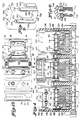
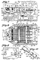
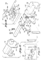
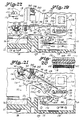
- Disjoncteur (20) qui comprend une paire, ou plus, de contacts séparables (30), chaque paire définissant un contact fixe (32) et un contact mobile (34) formant un pôle ; un conducteur (36), ou plus, côté ligne, chacun d'entre eux étant électriquement connecté audit contact fixe (32) ; un connecteur (46), ou plus, côté charge ; un circuit dérivé flexible (118), ou plus, connecté électriquement entre chacun desdits contacts mobiles (34) et lesdits conducteurs (46) côté charge ; chacun desdits circuits dérivés formés comme un élément en forme de V définissant une partie en forme d'anse (402), une première tige dépendante (168) reliée audit contact mobile (34) et une seconde tige dépendante (170) reliée audit conducteur (46) côté charge, créant un premier chemin de courant entre ladite première tige dépendante et ladite seconde tige dépendante et un second chemin de courant entre ladite seconde tige dépendante et ledit conducteur côté charge, ledit second chemin de courant provoquant la compression de ladite première tige dépendante par rapport à ladite seconde tige dépendante à une ampleur de courant prédéterminée, caractérisé en ce qu'une pièce d'écartement (400) peut fonctionner conjointement avec lesdites tiges dépendantes (168, 170) pendant des conditions de surcharge pour transmettre des forces de répulsion magnétiques générées entre ledit conducteur (46) côté charge et ladite tige dépendante (170) vers l'autre tige dépendante (168) réduisant, de ce fait, en grande partie, l'action de compression nécessaire entre lesdites tiges dépendantes et le temps nécessaire pour provoquer l'ouverture des contacts séparables (30).
- Disjoncteur selon la revendication 1, caractérisé en ce que la pièce d'écartement (400) est un élément rigide.
- Disjoncteur selon la revendication 2, caractérisé en ce que l'élément rigide est fait d'un matériau diélectrique.
- Disjoncteur selon la revendication 2 ou 3, caractérisé en ce que l'élément rigide est placé contigu à la première et la seconde tiges dépendantes.
- Disjoncteur selon la revendication 4, caractérisé en ce que l'élément rigide est normalement en contact avec une ou les deux première et seconde tiges dépendantes.
- Disjoncteur selon l'une quelconque des revendications 2 à 5, caractérisé en ce qu'un élément rigide est placé contigu à la partie en forme d'anse (402).
- Disjoncteur selon l'une quelconque des revendications 2 à 6, caractérisé en ce qu'un élément rigide est utilisé par pôle.
- Disjoncteur selon l'une quelconque des revendications 2 à 7, caractérisé en ce que l'élément rigide est formé comme un élément circulaire.
- Disjoncteur selon la revendication 8, caractérisé en ce que le diamètre de l'élément circulaire est en grande partie équivalent à la distance entre la première et la seconde tiges dépendantes à un point prédéterminé.
Applications Claiming Priority (2)
| Application Number | Priority Date | Filing Date | Title |
|---|---|---|---|
| US07/420,088 US4996507A (en) | 1988-08-01 | 1989-10-11 | CT quick change assembly and force transmitting spacer |
| US420088 | 1989-10-11 |
Publications (3)
| Publication Number | Publication Date |
|---|---|
| EP0422868A2 EP0422868A2 (fr) | 1991-04-17 |
| EP0422868A3 EP0422868A3 (en) | 1992-03-04 |
| EP0422868B1 true EP0422868B1 (fr) | 1995-08-09 |
Family
ID=23665032
Family Applications (1)
| Application Number | Title | Priority Date | Filing Date |
|---|---|---|---|
| EP90310999A Expired - Lifetime EP0422868B1 (fr) | 1989-10-11 | 1990-10-08 | Assemblage pour changer rapidement un transformateur de courant et entretoise de transmission de force |
Country Status (14)
| Country | Link |
|---|---|
| US (1) | US4996507A (fr) |
| EP (1) | EP0422868B1 (fr) |
| JP (1) | JPH03208223A (fr) |
| KR (1) | KR0148486B1 (fr) |
| CN (1) | CN1026372C (fr) |
| AU (1) | AU639262B2 (fr) |
| BR (1) | BR9005070A (fr) |
| CA (1) | CA2027009C (fr) |
| DE (1) | DE69021485T2 (fr) |
| IE (1) | IE903409A1 (fr) |
| MX (1) | MX166971B (fr) |
| NZ (1) | NZ235609A (fr) |
| PH (1) | PH27423A (fr) |
| ZA (1) | ZA907940B (fr) |
Families Citing this family (16)
| Publication number | Priority date | Publication date | Assignee | Title |
|---|---|---|---|---|
| FR2650434B1 (fr) * | 1989-07-26 | 1995-11-24 | Merlin Gerin | Disjoncteur basse tension a contacts multiples et a fortes intensites |
| US5160817A (en) * | 1990-11-21 | 1992-11-03 | Automatic Switch Company | Electrical switch contact arrangement having quick break arcing contacts |
| US5430420A (en) * | 1994-01-24 | 1995-07-04 | Eaton Corporation | Contact arrangement for a circuit breaker using magnetic attraction for high current trip |
| DE19522603A1 (de) * | 1995-06-19 | 1997-01-09 | Siemens Ag | Schutzeinrichtung gegen Überlastung der Schaltkontakte eines Schaltgerätes |
| US6225884B1 (en) | 1999-12-21 | 2001-05-01 | Eaton Corporation | Circuit breaker with mechanical trip load terminal/magnet barrier |
| US7016171B2 (en) * | 2001-02-01 | 2006-03-21 | Hydro-Aire, Inc. | Current fault detector and circuit interrupter and packaging thereof |
| WO2002082481A1 (fr) * | 2001-04-04 | 2002-10-17 | Siemens Aktiengesellschaft | Ensemble contact de commutation pour un commutateur electrique |
| US7211750B2 (en) * | 2004-12-22 | 2007-05-01 | Square D Company | Switching mechanism with shock absorber |
| JP2008041252A (ja) * | 2005-12-13 | 2008-02-21 | Mitsubishi Electric Corp | 回路遮断器 |
| US7777601B2 (en) | 2005-04-20 | 2010-08-17 | Mitsubishi Electric Corporation | Circuit breaker |
| US7351927B1 (en) * | 2006-10-13 | 2008-04-01 | Eaton Corporation | Electrical switch, conductor assembly, and independent flexible conductive elements therefor |
| US7646269B2 (en) * | 2007-03-07 | 2010-01-12 | Eaton Corporation | Electrical switching apparatus, and conductor assembly and shunt assembly therefor |
| GB201200331D0 (en) * | 2012-01-09 | 2012-02-22 | Dialight Europ Ltd | Improvements in switching contactors (II) |
| JP6244269B2 (ja) * | 2014-06-27 | 2017-12-06 | 株式会社日立製作所 | ガス遮断器 |
| DE102018113534B4 (de) * | 2018-06-06 | 2021-10-07 | Song Chuan Precision Co., Ltd. | Hochspannungs- und Hochstromrelais |
| CN113903633B (zh) * | 2021-09-24 | 2023-10-20 | 江苏佰瑞普智能科技有限公司 | 一种错误接线断电保护的接地故障断路保护器 |
Family Cites Families (8)
| Publication number | Priority date | Publication date | Assignee | Title |
|---|---|---|---|---|
| GB1053936A (fr) * | 1964-08-01 | |||
| US4489295A (en) * | 1982-12-17 | 1984-12-18 | Westinghouse Electric Corp. | Circuit interrupter with improved electro-mechanical undervoltage release mechanism |
| JPH0658785B2 (ja) * | 1985-06-12 | 1994-08-03 | 株式会社東芝 | 回路しや断器 |
| US4656444A (en) * | 1985-08-16 | 1987-04-07 | Westinghouse Electric Corp. | Circuit breaker with force generating shunt |
| US4638277A (en) * | 1985-10-01 | 1987-01-20 | Westinghouse Electric Corp. | Circuit breaker with blow open latch |
| DE3536112A1 (de) * | 1985-10-07 | 1987-04-09 | Siemens Ag | Kontaktanordnung fuer niederspannungs-leistungsschalter mit einem biegsamen stromband |
| US4679018A (en) * | 1986-01-15 | 1987-07-07 | Westinghouse Electric Corp. | Circuit breaker with shock resistant latch trip mechanism |
| DE3708807A1 (de) * | 1987-03-18 | 1988-10-06 | Licentia Gmbh | Elektrischer leistungsschalter mit einem elektro-dynamisch oeffnenden kontaktsystem |
-
1989
- 1989-10-11 US US07/420,088 patent/US4996507A/en not_active Expired - Lifetime
-
1990
- 1990-09-21 IE IE340990A patent/IE903409A1/en unknown
- 1990-09-28 AU AU63705/90A patent/AU639262B2/en not_active Ceased
- 1990-10-04 ZA ZA907940A patent/ZA907940B/xx unknown
- 1990-10-04 MX MX022690A patent/MX166971B/es unknown
- 1990-10-05 CA CA002027009A patent/CA2027009C/fr not_active Expired - Fee Related
- 1990-10-08 PH PH41339A patent/PH27423A/en unknown
- 1990-10-08 EP EP90310999A patent/EP0422868B1/fr not_active Expired - Lifetime
- 1990-10-08 DE DE69021485T patent/DE69021485T2/de not_active Expired - Fee Related
- 1990-10-09 NZ NZ235609A patent/NZ235609A/en unknown
- 1990-10-10 KR KR1019900015996A patent/KR0148486B1/ko not_active IP Right Cessation
- 1990-10-10 BR BR909005070A patent/BR9005070A/pt active Search and Examination
- 1990-10-11 JP JP2273124A patent/JPH03208223A/ja active Pending
- 1990-10-11 CN CN90108282A patent/CN1026372C/zh not_active Expired - Fee Related
Also Published As
| Publication number | Publication date |
|---|---|
| CA2027009A1 (fr) | 1991-04-12 |
| PH27423A (en) | 1993-06-21 |
| IE903409A1 (en) | 1991-04-24 |
| CN1050945A (zh) | 1991-04-24 |
| EP0422868A2 (fr) | 1991-04-17 |
| EP0422868A3 (en) | 1992-03-04 |
| JPH03208223A (ja) | 1991-09-11 |
| BR9005070A (pt) | 1991-09-17 |
| NZ235609A (en) | 1994-01-26 |
| KR910008765A (ko) | 1991-05-31 |
| DE69021485T2 (de) | 1996-03-21 |
| CA2027009C (fr) | 2000-08-22 |
| MX166971B (es) | 1993-02-16 |
| DE69021485D1 (de) | 1995-09-14 |
| US4996507A (en) | 1991-02-26 |
| KR0148486B1 (ko) | 1998-11-16 |
| ZA907940B (en) | 1992-06-24 |
| AU6370590A (en) | 1991-04-18 |
| AU639262B2 (en) | 1993-07-22 |
| CN1026372C (zh) | 1994-10-26 |
Similar Documents
| Publication | Publication Date | Title |
|---|---|---|
| US4951019A (en) | Electrical circuit breaker operating handle block | |
| EP0353950B1 (fr) | Butées de caoutchouc dans des pôles extérieurs | |
| EP0353948B1 (fr) | Assemblage laminé de cuivre | |
| EP0422868B1 (fr) | Assemblage pour changer rapidement un transformateur de courant et entretoise de transmission de force | |
| EP0353940B1 (fr) | Assemblage de barre transversale | |
| US4887057A (en) | Cam roll pin assembly | |
| US4951020A (en) | Unriveted upper link securement cross-reference to related applications | |
| EP0353939B1 (fr) | Méthode pour changer rapidement un transformateur de courant | |
| US4939491A (en) | Combination barrier and auxiliary CT board | |
| EP0353949B1 (fr) | Assemblage d'une plate-forme modulaire d'option | |
| EP0353951B1 (fr) | Barrière de combination et panneau d'un transformateur auxiliaire de courant | |
| IE73215B1 (en) | Crossbar assembly | |
| NZ229875A (en) | Circuit breaker modular option deck |
Legal Events
| Date | Code | Title | Description |
|---|---|---|---|
| PUAI | Public reference made under article 153(3) epc to a published international application that has entered the european phase |
Free format text: ORIGINAL CODE: 0009012 |
|
| AK | Designated contracting states |
Kind code of ref document: A2 Designated state(s): DE FR GB IT |
|
| PUAL | Search report despatched |
Free format text: ORIGINAL CODE: 0009013 |
|
| AK | Designated contracting states |
Kind code of ref document: A3 Designated state(s): DE FR GB IT |
|
| 17P | Request for examination filed |
Effective date: 19920707 |
|
| 17Q | First examination report despatched |
Effective date: 19931213 |
|
| RAP1 | Party data changed (applicant data changed or rights of an application transferred) |
Owner name: EATON CORPORATION |
|
| GRAA | (expected) grant |
Free format text: ORIGINAL CODE: 0009210 |
|
| AK | Designated contracting states |
Kind code of ref document: B1 Designated state(s): DE FR GB IT |
|
| REF | Corresponds to: |
Ref document number: 69021485 Country of ref document: DE Date of ref document: 19950914 |
|
| ITF | It: translation for a ep patent filed |
Owner name: ING. C. GREGORJ S.P.A. |
|
| ET | Fr: translation filed | ||
| PLBE | No opposition filed within time limit |
Free format text: ORIGINAL CODE: 0009261 |
|
| STAA | Information on the status of an ep patent application or granted ep patent |
Free format text: STATUS: NO OPPOSITION FILED WITHIN TIME LIMIT |
|
| 26N | No opposition filed | ||
| REG | Reference to a national code |
Ref country code: GB Ref legal event code: IF02 |
|
| PGFP | Annual fee paid to national office [announced via postgrant information from national office to epo] |
Ref country code: DE Payment date: 20031031 Year of fee payment: 14 |
|
| PG25 | Lapsed in a contracting state [announced via postgrant information from national office to epo] |
Ref country code: DE Free format text: LAPSE BECAUSE OF NON-PAYMENT OF DUE FEES Effective date: 20050503 |
|
| PG25 | Lapsed in a contracting state [announced via postgrant information from national office to epo] |
Ref country code: IT Free format text: LAPSE BECAUSE OF NON-PAYMENT OF DUE FEES Effective date: 20051008 |
|
| PGFP | Annual fee paid to national office [announced via postgrant information from national office to epo] |
Ref country code: GB Payment date: 20070918 Year of fee payment: 18 |
|
| PGFP | Annual fee paid to national office [announced via postgrant information from national office to epo] |
Ref country code: FR Payment date: 20081006 Year of fee payment: 19 |
|
| GBPC | Gb: european patent ceased through non-payment of renewal fee |
Effective date: 20081008 |
|
| PG25 | Lapsed in a contracting state [announced via postgrant information from national office to epo] |
Ref country code: GB Free format text: LAPSE BECAUSE OF NON-PAYMENT OF DUE FEES Effective date: 20081008 |
|
| REG | Reference to a national code |
Ref country code: FR Ref legal event code: ST Effective date: 20100630 |
|
| PG25 | Lapsed in a contracting state [announced via postgrant information from national office to epo] |
Ref country code: FR Free format text: LAPSE BECAUSE OF NON-PAYMENT OF DUE FEES Effective date: 20091102 |