EP0421912A2 - Emergency mobilization system - Google Patents
Emergency mobilization system Download PDFInfo
- Publication number
- EP0421912A2 EP0421912A2 EP90630171A EP90630171A EP0421912A2 EP 0421912 A2 EP0421912 A2 EP 0421912A2 EP 90630171 A EP90630171 A EP 90630171A EP 90630171 A EP90630171 A EP 90630171A EP 0421912 A2 EP0421912 A2 EP 0421912A2
- Authority
- EP
- European Patent Office
- Prior art keywords
- mobilization
- emergency
- recipient
- message
- messages
- Prior art date
- Legal status (The legal status is an assumption and is not a legal conclusion. Google has not performed a legal analysis and makes no representation as to the accuracy of the status listed.)
- Withdrawn
Links
Images


Classifications
-
- H—ELECTRICITY
- H04—ELECTRIC COMMUNICATION TECHNIQUE
- H04M—TELEPHONIC COMMUNICATION
- H04M3/00—Automatic or semi-automatic exchanges
- H04M3/42—Systems providing special services or facilities to subscribers
-
- H—ELECTRICITY
- H04—ELECTRIC COMMUNICATION TECHNIQUE
- H04M—TELEPHONIC COMMUNICATION
- H04M11/00—Telephonic communication systems specially adapted for combination with other electrical systems
- H04M11/02—Telephonic communication systems specially adapted for combination with other electrical systems with bell or annunciator systems
-
- Y—GENERAL TAGGING OF NEW TECHNOLOGICAL DEVELOPMENTS; GENERAL TAGGING OF CROSS-SECTIONAL TECHNOLOGIES SPANNING OVER SEVERAL SECTIONS OF THE IPC; TECHNICAL SUBJECTS COVERED BY FORMER USPC CROSS-REFERENCE ART COLLECTIONS [XRACs] AND DIGESTS
- Y10—TECHNICAL SUBJECTS COVERED BY FORMER USPC
- Y10S—TECHNICAL SUBJECTS COVERED BY FORMER USPC CROSS-REFERENCE ART COLLECTIONS [XRACs] AND DIGESTS
- Y10S379/00—Telephonic communications
- Y10S379/904—Auto-calling
-
- Y—GENERAL TAGGING OF NEW TECHNOLOGICAL DEVELOPMENTS; GENERAL TAGGING OF CROSS-SECTIONAL TECHNOLOGIES SPANNING OVER SEVERAL SECTIONS OF THE IPC; TECHNICAL SUBJECTS COVERED BY FORMER USPC CROSS-REFERENCE ART COLLECTIONS [XRACs] AND DIGESTS
- Y10—TECHNICAL SUBJECTS COVERED BY FORMER USPC
- Y10S—TECHNICAL SUBJECTS COVERED BY FORMER USPC CROSS-REFERENCE ART COLLECTIONS [XRACs] AND DIGESTS
- Y10S379/00—Telephonic communications
- Y10S379/905—Fax mail
Definitions
- the present invention relates to message management systems generally and to emergency mobilization message management systems in particular.
- the present invention seeks to provide a highly efficient and economical emergency crew mobilization system.
- an emergency mobilization system comprising a network of mobilization devices each comprising apparatus for producing messages and apparatus for transmitting at least one message by telephone to each of a plurality of recipient apparatus each associated with at least one recipient.
- Each recipient apparatus typically comprises at least one of the following: facsimile machines, pagers, telephones or computer terminals connected to a host computer.
- the apparatus for transmitting comprises apparatus for receiving acknowledgements of receipt of the messages from the recipients.
- the acknowledgements can be in the form of vocal replies or in the form of a code entered in DTMF or in pulse or speech or in the form of a fax and can be transferred to the sender of the message in the form of spoken messages for vocal replies or in the form of a fax or in the form of a printed or displayed report.
- the message may be a recorded mobilization message or a notification that a mobilization message awaits the recipient.
- the apparatus for transmitting comprises apparatus for dialling to the recipient apparatus and apparatus for outputting the mobilization message to a recipient only if the recipient apparatus goes OFF-HOOK.
- the apparatus for transmitting comprises apparatus for sending the mobilization message to mailboxes belonging to the recipients, apparatus for dialling to the recipient apparatus and apparatus for outputting a notification that a message awaits the recipient in the mailbox to each recipient only if his recipient apparatus goes OFF-HOOK. Once the recipient has identified himself to the mailbox, the mobilization message is transmitted to the recipient.
- the apparatus for dialling redials to the recipient apparatus until either the recipient responds or a predetermined number of redials has elapsed.
- the apparatus for dialling redials to the recipient apparatus until either the recipient accesses his mailbox or a predetermined number of redials has elapsed.
- the redialling to the recipient apparatus is performed in accordance with a predefined plan which states the number of redials and the time between the redials in accordance with the dial result and with the priority attached to the mobilization message.
- the mobilization apparatus includes apparatus for defining a backup recipient for each recipient where the backup recipient will receive the mobilization message if the recipient is unavailable, i.e. if a predetermined number of retries has taken place without success.
- each mobilization apparatus includes apparatus for creating and storing a plurality of mobilization lists wherein each of the mobilization lists is a list of at least one recipient to be mobilized.
- the mobilization list can also comprise a locating list for mobilizing a first predefined number of recipients on the mobilization list who are successfully contacted.
- the apparatus for creating and storing comprises a telephone, a console attached to the mobilization device, or a host computer connected to the mobilization device.
- the mobilization message comprises a prerecorded message.
- the apparatus for producing messages can record the mobilization message shortly before the time of transmission of the mobilization message.
- the apparatus for transmitting concurrently and asynchronously sends a multiplicity of copies of the messages on a multiplicity of separate telephone lines.
- a multiplicity of versions of the messages can be sent.
- each mobilization device also includes apparatus for providing information on the status of the mobilization to an authorized supervisor via telephones, terminal displays, facsimile reports, printers, or communication with a host computer.
- means is provided to enable one of the mobilization devices in the network to originate an emergency mobilization procedure and instruct a multiplicity of the mobilization devices in the network to perform the mobilization. It is appreciated that the mobilization of different groups may be performed concurrently and independently for each group.
- each mobilization device includes apparatus for receiving a multiplicity of instruction inputs for selectably mobilizing a multiplicity of groups of recipient apparatus within the plurality of recipient apparatus.
- each mobilization device mobilizes recipient apparatus located within a local region of the mobilization device.
- at least one backup mobilization device is defined wherein the backup mobilization device belongs to the network. Additional redundancy is achieved through building each mobilization device as a twin mobilization device.
- initiation of a local mobilization procedure may be performed on any one of the mobilization devices in the network via any suitable telephone.
- the apparatus for producing messages comprises at least one of the following: telephone apparatus, telephone apparatus in association with DTMF acoustic diallers, telephone apparatus in association with facsimile machines and telephone apparatus associated with computer apparatus.
- each mobilization device also comprises apparatus for providing a store and forward function.
- the apparatus for providing a store and forward function also comprises interconnect subsystem apparatus arranged to interconnect with telephone switching apparatus, a control subsystem for providing control instructions to the interconnect subsystem apparatus, including instructions for transmitting and receiving voice and fax messages, and mass storage subsystem apparatus coupled to the control subsystem for storing voice transmissions.
- each mobilization device may also comprise apparatus for storing voice messages, images, and messages combining voice and images.
- a method of mobilizing emergency personnel including the steps of instructing an originator mobilization device to perform a specified mobilization and instruction by the originator mobilization device to a plurality of mobilization devices belonging to a network each to mobilize a specific group of recipients.
- the step of instruction includes the steps of transmission of at least one message from one of the plurality of mobilization devices to each one of its respective specific group of recipients and of recording the success or failure to transmit the at least one message.
- the step of transmission of messages includes the steps of receiving an acknowledgement receipt from a multiplicity of the recipients and of recording the acknowledgement receipts.
- the method of mobilizing emergency personnel also includes the step of reporting the status of the mobilization.
- the emergency mobilization system comprises a multiplicity of mobilization apparatus 1 each in telephonic communication with at least one public telephone switch 2. Additionally, the emergency mobilization system of the present invention typically operates in conjunction with at least one alert network which comprises the hierarchy of people to be mobilized.
- an initator in an alert network control center 3 responsible for the mobilization dials the mobilization apparatus 1 corresponding to that control center 3, creates a mobilization message, and instructs the apparatus 1 to perform a specific mobilization procedure.
- the initiator is a preliminary message sender; other mobilization personnel can create and send mobilization messages, as will be described hereinbelow.
- a mobilization procedure typically is performed by mobilizing personnel who are identified on a mobilization list.
- the mobilization apparatus 1 typically has stored in it a number of previously defined lists of personnel to be mobilized.
- the personnel to be mobilized will be known hereinafter as 'recipients'. Recipients are divided into two classes, subscribers, for each whom there is defined in apparatus 1 a private profile record and optionally, a private mailbox, and non-subscribers whose name and telephone numbers at which they can be reached are recorded on the mobilization list.
- the private profile record typically comprises definitions of private parameters, such as an address and a plurality of telephone numbers, at which the subscriber can be reached.
- the subscriber's private mailbox is defined as a storage place in apparatus 1 which typically stores arriving messages.
- the mobilization list is typically created and modified via a console which may be an element of mobilization apparatus 1, via a host computer connected to mobilization apparatus 1 or via a telephone.
- the mobilization list, or lists may be created before the moment of the emergency and stored within the mobilization apparatus 1. Alternatively, it may be created at the time of initiation of the mobilization.
- the mobilization fist may comprise a record for a single recipient or it may comprise a plurality of records, one per a plurality of recipients. Additionally, the recipients may be subscribers and/or non-subscribers.
- mobilization apparatus 1 Upon notification of a mobilization, mobilization apparatus 1 dials to each of the recipients on the mobilization list, via the public telephone switches 2 in its region.
- the recipient may receive the phone call either at a private telephone 4, a public telephone 6, a cellular phone 8 via a cellular telephone switch 9, via a pager 11, or via any other suitable telephonic means.
- the mobilization apparatus 1 plays the mobilization message, typically twice, when someone at the telephone number of the non-subscriber responds to the phone call. If the person answering the telephone is not the non-subsciber, it is expected that that person will transmit the mobilization message to the non-subscriber.
- mobilization apparatus 1 typically sends the mobilization message to each subscriber's mailbox.
- Apparatus 1 dials each subscriber and plays a predefined notification message which notifies the subscriber to access his mailbox. If desired by the recipient, the notification can be made repeatedly, typically until the subscriber accesses his mailbox.
- the mobilization apparatus plays the notification message to whom- ever picks up the telephone. If the subscriber is the one to pick up the telephone, the subscriber can immediately identify himself to the system and receive the mobilization message. If somebody else picked up the telephone and then ntoified the subscriber, the subscriber can dial to the system, identify himself and receive the mobilization message. This method of sending messages enhances the confidentiality of the mobilization and enables the sender to create detailed messages.
- the amount of time between attempts to notify a subscriber, or to access a non-subscriber, as well as the number of such attempts is typically defined according to a predefined plan and is a function of the dial result, such as busy, no answer, etc., the number of tries previously attempted, and of the priority given to the notification or mobilization message, respectively.
- the retry periodicity may be a function of the number of previous unsuccessful attempts.
- the mobilization message may have been recorded some time before the start of the mobilization or a sender may record it immediately before sending it.
- the mobilization apparatus 1 typically is capable of concurrently and asynchronously accessing multiple, typically 32, recipients via the at least one telephone switch 2. Apparatus 1 typically will play the same mobilization message to each of the multiple recipients. Alternatively, a multiplicity of different messages can be played. In either case, for each recipient, the message is played starting from the beginning of the message.
- mobilization apparatus 1 may request an acknowledgement of receipt of the message.
- the acknowledgement typically comprises the recording of a vocal reply or the entering of a code, either via pulse or DTMF dialling, or via speech recognition. Any unreceived messages are returned to the sender after a predetermined number of retries have occurred or a predetermined amount of time has elapsed.
- each recipient is associated with a backup recipient who will receive his messages if he does not answer within the predetermined amount of time. This is known as cascading and it is typically organized by having each recipient define who his backup recipient is.
- the cascading can be organized in a number of ways, as shown in Fig. 3.
- the recipients can be serially cascaded, as shown by (a), such that the apparatus 1 first attempts to access a main recipient 13. If main recipient 13 is unavailable, the apparatus 1 attempts to access a backup recipient 15. If the backup recipient 15 is unavailable, the apparatus 1 returns a message to the sender indicating its inability to access anyone.
- serially cascading can be longer, as shown in (b).
- the cascading is typically organized in a loop as shown in (c) where apparatus 1 first dials recipient 13, then recipient 15 and then recipient 17. If none of them respond, then apparatus 1 retries recipient 13 and so on until a reply is received.
- recipients 19 and 21 are backed up by recipient 25 who, in turn, is backed up by recipient 29.
- Recipient 23 is backed up by recipient 27 who is also backed up by recipient 29.
- a loop can be included, as shown between recipients 27 and 29.
- the mobilization list can be utilized as a mailing list, where the message is sent to all recipients. Apparatus 1 notifies the sender of recipients which received and those who did not receive the message.
- the mobilization list can be utilized as a locating list where the sender requires that the message be received by a predetermined number of recipients listed on the mobilization list. Typically, once the predetermined number of recipients have responded, mobilization apparatus 1 no longer attempts to mobilize the remaining personnel on the list, if any exist.
- each apparatus 1 typically only accesses recipients located in the area near its location, the originally notified apparatus 1 may additionally notify other apparatus 1 to send the mobilization message to recipients in their areas.
- the apparatus 1 can be organized into a network covering a large area, in order to effect the mobilization of a large population. Additionally, by spreading the mobilization activity among a multiplicity of regional mobilization apparatus 1, the number of long-dis - tance telephone calls is reduced.
- Fig. 2 illustrates an example network of apparatus 1.
- the network comprises a plurality of apparatus 1 distributed throughout a given region, typically of a state or country, where each apparatus 1 serves the geographical region in which it is located.
- the at least one alert network comprises the alert network control center 3, a multiplicity of regional control centers 31 and a plurality of local control centers 33.
- Each local control center 33 is responsible for overseeing the mobilization occurring within a small geographic location and for reporting to a regional control center 31.
- Each regional control center 31 receives information as to the status of the mobilization within its region and reports that information to the alert network control center 3, which is responsible for the overall mobilization.
- the mobilization is typically initiated from the alert network control center 3 which dials the mobilization apparatus 1 assigned to it, marked 1A on Fig. 2.
- Apparatus 1A is typically the apparatus 1 which is closest to alert network control center 3.
- Apparatus 1A then dials the other apparatus 1 which service the alert network, in accordance with instructions from the alert network control center 3, and transmits to them information regarding the current emergency mobilization, such as the message to send, the specific mobilization list or lists to use, etc.
- the initiator selects, or creates, a mobilization list of those personnel. If only a few of the personnel with the required skills are needed, apparatus 1 will then use the list as a locating list and will mobilize the required number of people. If the personnel with the skills are located in a number of regions, then one of the apparatus 1 will be assigned the job of mobilizing them, thus requiring it to mobilize some people outside of its region.
- controllers in each local control center 33 dial their respective apparatus 1 and receive reports from the apparatus 1 on the status of the mobilization procedure (e.g. number of acknowledgements, the acknowledgements themselves, a list of people unsuccessfully contacted, etc). They then can instruct the apparatus 1 assigned to them with additional instructions, such as the sending of new mobilization messages or the mobilization of a new group of people. Additionally, the local controllers report to the regional control center 31 typically by sending messages from their apparatus 1 to mailboxes of the regional controllers in the apparatus 1 assigned to the regional control center 31.
- the reports can be received via a telephone, via a facsimile machine, via a printer or via a display apparatus connected to a host computer.
- the regional control center 31 receives status reports from a plurality of local controllers. Similarly to the local controllers, the regional controllers can issue additional mobilization instructions to the apparatus 1 assigned to them and they can report the status of the regional mobilization to the alert network control center 3. They can also send, messages to the local controllers with instructions concerning additional mobilizations to perform or with other information concerning the emergency mobilization.
- the alert network control center 3 receives reports from the regional controllers via apparatus 1A. It additionally can request reports from appara - tus 1A describing the status of the mobilization of the personnel in the local area near control center 3. However, typically, there is a local control center 33 assigned to apparatus 1 A, which receives the status reports from apparatus 1 A and reports the results to the regional control center 31 who then reports to alert network control center 3.
- each apparatus 1 additionally stores the mobilization lists and other information concerning the recipients of at least one neighboring apparatus 1. This provides redundancy in the mobilization system of the present invention and ensures that a mobilization can be performed even if a portion of the apparatus 1 and/or the telephony environment is not functioning. Additionally, for redundancy purposes, each apparatus 1 is a twin apparatus 1 to ensure that if one of twins is not functioning, the other one is operative.
- a plurality of independent alert networks can typically be defined over the network of apparatus 1, as illustrated in Fig. 4.
- the state may choose to utilize it to define independent alert networks for the state police, the army, the reserves, local fire and police departments, and for hospitals.
- Each organization can define multiple alert networks, typically ranging from total mobilization to partial mobilization, such as a skeleton mobilization.
- mobilization of any organization can be performed in stages, if necessary. It can begin with a skeleton mobilization and then proceed through a partial mobilization to a full mobilization.
- a staggered mobilization such as is described hereinabove, can be performed manually, by dialling the apparatus 1 A each time a different level of mobilization is required and at that time, instructing apparatus 1 A as to which mobilization list to use, or it can be performed automatically, by assigning a specific time when a mobilization list is to be used or by assigning priorities to the messages sent by the different mobilization lists.
- the automatic priority mobilization will be performed by allocating the entirety of the resources of the network of apparatus 1 to the mobilization lists having the highest priority. As more and more of the highest priority personnel have been contacted, the network allocates more and more resources to the next highest priority mobilization list. The process proceeds until all personnel on the mobilization lists have been contacted.
- the mobilization procedure described hereinabove pertains to a multi- regional emergency mobilization. It is also possible to perform a local mobilization utilizing one or a few of the apparatus 1. In the local case, the local or regional controllers are responsible for the mobilization and there is no need for them to report to an alert network control center.
- the emergency mobilization apparatus of the present invention supports a message file system and receives and stores voice and image records in subscriber's mailboxes.
- the mobilization apparatus 1 of the present invention is capable of informing a subscriber when a voice message or a facsimile record, has been placed in his mailbox. As mentioned hereinabove, the apparatus 1 informs the subscriber by calling him over the telephone or by any other suitable technique.
- the apparatus using any DTMF telephone or DTMF acoustic dialler, scans the subscriber's mailbox for messages which are either voice messages or facsimile records. The subscriber can then hear or view his messages, delete or keep them, reply to the sender, or forward them to another subscriber, while optionally adding annotation.
- the subscriber can also forward his voice or facsimile messages to any other subscriber's mailbox anywhere over the telephone network via a telephone, a specially equipped personal computer or a facsimile system.
- the user can also retrieve the facsimile message immediately at a facsimile machine or at a specially equipped PC connected to his telephone line. He can control both transmission and retrieval of the facsimile message from his telephone keypad.
- Equipment for suitable adaptation of a PC is available from TITN Inc. and GAMALINK both of the U.S.A.
- the apparatus 1 supports the addition of a voice annotation to a facsimile record and linking of facsimile records into multirecord facsimile files.
- Any subscriber can create and send a voice message or a facsimile record to any telephone number or subscriber.
- Any non-subscriber may create and send a voice message or a facsimile record to any subscriber.
- Voice or facsimile records may be sent to a subscriber's mailbox by specifying his ID or extension number within an office and to a facsimile system (or specially equipped PC) by specifying its extension number within an office.
- Voice or facsimile records may be sent to a non-subscriber's facsimile by specifying its telephone number as well as to a list of subscribers, non-subscribers, and facsimile systems.
- Notification of the arrival of a voice or facsimile record to a subscriber's mailbox is preferably pro-' vided by a telephone call to a prespecified telephone number. Additionally, the notification may be made by activating a 'message waiting' indicator light on the subscriber's telephone, by activating a pager, or by display of the subscriber's mailbox identification code on a display or a printer.
- the entire interaction of the user (subscriber or non-subscriber) with the apparatus 1 is typically carried out over the telephone.
- the user is guided with voice prompts and controls the apparatus 1 with DTMF keystrokes or with voice commands.
- Sending a facsimile to a subscriber and receiving it and programming the telephone number for notification are all done over the telephone.
- a special option of the apparatus 1 is the support of DID lines with associated subscribers' mailboxes.
- the user may call such an appropriate DID number to send or receive a voice message or facsimile. This eliminates the need for DTMF telephone sets.
- the emergency mobilization apparatus of the present invention typically supports up to 32 lines of voice where, of those 32 lines, 20 lines may support facsimile data.
- the apparatus 1 comprises a control subsystem 10 which is coupled to one or more mass storage subsystems 12 via a SASI bus 14.
- the control subsystem 10 is also coupled to a host computer (not shown) via an RS 232, Ethernet link (not shown) or an X.25 network 18.
- the X.25 network 18 additionally allows each apparatus 1 to communicate with other apparatus 1.
- Control subsystem 10 is also coupled to a public telephone switch 2 for communication with telephonic environments.
- Control subsystem 10 is coupled via one or more LBX busses 32 to a plurality of line subsystems 34, each of which is adapted to interface with a public telephone switch 2 as well as with telephones and facsimile machines, directly or via a central telephone office.
- the line subsystem comprises an MTU interface card 50, which is described hereinbelow in connection with Fig. 9, and which is connected to the control subsystem via the LBX bus 32 (Fig. 5).
- the MTU interface card 50 is coupled via an extender card 52 to a sub LBX parallel bus 54 and to a PCM highway serial bus 56.
- a plurality of signal processing units (SPU) 58, and optionally, a facsimile processing unit (FPU) 57, are coupled to the busses 54 and 56.
- a schematic illustration of a preferred facsimile processing unit (FPU) appears at Fig. 41.
- a plurality of telephone interface units (TIU) 60 are connected to the PCM highway bus 56 and are connected to telephone lines via an RJIIC connection.
- the control subsystem 10 comprises two line CPUs (LCU) 70, such as an ESBC 86 manufactured by the present applicants/assignees and illustrated in detail in Fig. 42.
- the LCU 70 is preferably similar to a combination of the ISBC 186/03 of Intel and a memory, such as an Intel SBC12 CX memory.
- Each LCU 70 is coupled a line subsystem 34 via an LBX bus 32.
- the LCUs 70 are connected to a multibus 74. Also connected to multibus 74 are a mass storage controller 76, coupled via SASI bus 14 to the mass storage subsystem 12, a main CPU (MCU) 80, such as an SBC 286/14 of Intel, a host computer interface 82, such as an Intel SBC 544, an optional ethernet interface (not shown), such as an Intel SBC 552, and an X.25 interface 86, such as an Intel SBC 188/56.
- MCU main CPU
- host computer interface 82 such as an Intel SBC 544
- an optional ethernet interface not shown
- an Intel SBC 552 an optional ethernet interface
- X.25 interface 86 such as an Intel SBC 188/56.
- a preferred software object listing for the EPROM of the MCU 80, when embodied in an Intel 286/14 is attached hereto as Software Annex E.
- subsystem 12 comprises a primary mass storage unit 90 including a plurality of controllers 92, such as OMTI 5200 cards, each of which operates a pair of disk drives 94 and 96.
- controllers 92 such as OMTI 5200 cards
- Each mass storage subsystem may also include a floppy drive 98.
- Subsystem 12 also typically comprises a secondary mass storage unit 106 which is similar to unit 90 except that it typically comprises at least one additional disk drive 108, operated by a separate controller 110.
- PSU circuits 100, 102 and 104 provide power to the various components.
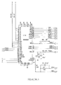
- Fig. 9 is a block diagram illustration of MTU circuitry forming part of the line subsystem shown in Fig. 6.
- Figs. 13-16 are schematic illustrations of the circuitry of Fig. 9.
- the general function of the MTU circuitry is to provide an interface between the LBX bus 32 and the subLBX parallel bus 54 enabling a LCU 70 (Fig. 7) to access the SPU circuits 58 (Fig. 6).
- the MTU circuitry generates the necessary timing signals for providing control of the operation of the TIU circuits 60.
- Address bus signals ABO - AB19 received along the LBX bus, are processed in the following manner: Signals ABO, AB10 -AB19 are fed to a line receiver 200 which shapes the signals and outputs to an address decoder 202, which generates timing signals BDSEL, DSPCS and IOSEL.
- Timing signal IOSEL is employed to gate the access of the LCU 70 to the MTU circuitry 50.
- Timing signal DSPCS is employed to gate the access of the LCU 70 to the SPU circuits 58.
- Timing signal BDSEL is employed to gate timing generation circuitry 204 and 206.
- Address signals ABO - AB16 supplied from LBX bus 32 are supplied to line drivers 208, 210 and 212 which define a three state buffer 214, which outputs buffered signals LAO - LA 16 to the sub LBX parallel bus 54.
- Buffered address signals BADO, BAD10 and BAD11 from line receiver 200 and timing signal IOSEL are supplied to an address decoder 216, which provides chip selection and initialization logic functions.
- Data signals LDO - LD15 from LBX bus 32 are coupled to transceivers 218, 220 and 222, which are collectively indicated on Fig. 9 by reference numeral 217.
- the transceivers which operate in both directions, shape and buffer the signals, and are are also coupled to subLBX data signals DO - D15.
- Data transceiver 220 is employed to provide a swapping operation for a double 8 bit transfer by a 16 bit bus.
- the operations of transceivers 218, 220 and 222 are controlled by timing signals EVENEN/, SWAPEN/ and ODDEN/, generated by timing circuitry 224.
- Timing signals BDSEL, STDSTB, LBHEN and BADO are fed to timing circuitry 224, an address decoder 226 and logic gates 228 and 230.
- a real time clock 232 supplies real time information (time and date) to the LCU 70, which accesses clock 232 using timing and address signals LA1 - LA4, DLWT/, DLRD/ and data bus signals DO - D3.
- the clock 232 receives electrical power from a power supply back up circuitry 234.
- Status input circuitry 236 provides conversion of analog signals from the subLBX bus to digital signals that can be read by the LCU 70 and includes a line receiver 238.
- Wait state generator and delay circuitry 240 includes shift register 204 and 206 flip flops 258, 260, 262, 264 and 266 and a decoder 268. Gating signals ADSTB/ and DSTB are buffered by a line receiver 270 which outputs a buffered signal BDSTB to flip flop 266 and a buffered signal BADSTB/ to flip flop 264 via a gate 272.
- a clock signal CLK8HZ together with gating signals BLSEL, DSPCS and IOSEL are supplied to shift registers 204 and 206 which output timing signals DLDSTB, DLWT/, LACK/. These timing signals are delayed versions of the corresponding inputs to the shift registers 204 and 206 and are used to gate input-ouput operations of the rest of the circuitry.
- the MTU circuitry 50 also includes timing circuitry for the the TIU and SPU circuitry 58 and 60 respectively.
- This timing circuitry comprises an oscillator 280, which outputs a 16 MHZ clock signal to divider circuitry 282, which includes counters 284, 286, 288, 290, 292 and 294. Outputs of these counters are supplied to timing logic circuitry 296, which comprises a shift register 298 and flip flops 300 and 302. Outputs from timing logic circuitry 296 and divider circuitry 282 are supplied to line driver circuitry 304 which outputs the following timing signals to the subLBx bus 54: SYNC256, PCNCK, CLK16, Q3SH and SINC64.
- Fig. 10 is a block diagram illustration of SPU circuitry forming part of the line subsystem shown in Fig. 6.
- Figs. 11 and 12 are schematic illustrations of the circuitry of Fig. 10.
- the SPU circuitry of Fig. 10 comprises interface circuitry indicated generally by reference numerals 350 and 351 in addition to digital signal processing devices 352 and 354.
- Interface circuitry 350 provides switch bank based communication between devices 352 and 354 on the one hand and LCU 70 on the other hand via subLBX bus 54.
- the circuitry of Fig. 10 may also be adapted to provide fax modem functions.
- the LCU 70 can access RAM banks A or B, respectively indicated by reference numerals 356 and 358 via six of twelve 3-state transceivers 360, 362, 364 and 366 and 3-state buffers 368, 370, 372, 374, 376, 378, 380 and 382.
- 3-state buffers 368, 370, 372 and 374 are used to switch the address signals CABO - CAB12 from the subLBx bus 54 and control signals CCS, SWR and CRD from a decoder 384 to the RAM banks A and B, while 3-state buffers 376, 378, 380 and 382 are used to switch the address signals NABO - NAB 12 from address translation circuitry 394 and control signals NCS, SWR and NRD from parallel read- write logic circuitry 388 to RAM banks A and B.
- Three-state transceivers 360, 362, 364 and 366 are used to switch data signals CDBO - CDB7 from subLBX bus 54 and NDBO - NDB7 from devices 352 and 354 to the RAM banks A and B.
- a line receiver 390 shapes control signals A1, DSTB, R/W, A13 - 16, and LES from the subLBX bus 54.
- Line receiver 390 outputs corresponding buffered signals to decoder 384, which in turn, outputs control signals SW1, SW2 and ESW which are directed to the remainder of the SPU circuitry.
- Sync counters 392 and address translation circuitry 394 are employed to generate address signals NABO - NAB12.
- Timing circuitry 396 which comprises flip flops 398 and 400 and logic gates 402 and 404, together with decoder 386 generate timing signals used to read the serial PCM information into the devices 352 and 354.
- Fig. 17 is a block diagram illustration of the TIU circuitry and to Figs. 18 - 21 which together are a schematic illustration of this circuitry.
- the general function of the TIU circuitry is to interface the store and forward system of the present invention to subscriber telephone lines.
- the TIU circuitry converts the analog signals on the subscriber telephone lines to digital form suitable for further processing by the SPU circuits 58. Additionally the TIU circuitry controls the conventional telephone operations such as OFF HOOK/ON HOOK.
- a subscriber telephone line is connected to an active hold and feed circuit 450, to ring and current detect circuit 452 and to a transformer 454.
- ring detect circuit 452 converts the ringing signal into a logic level which is transferred to parallel to serial conversion circuits 456. These circuits transmit the converted signal through PCM highway 56 (Fig. 6) to the spin circuits for further processing.
- the apparatus 1 When the apparatus 1 answers the subscriber's call, it provides an OFF HOOK operation in the following manner:
- This waveform is transmitted along PCM highway 56 to the SPU circuitry 58 for compression and further processing.
- the apparatus 1 outputs audio signals to the subscriber line using the following method:
- the audio from the transformer 454 is also fed to the DTMF receiver 468.
- This receiver detects DTMF dialing tones and converts them into 4 bit digital data. This data is coupled onto the PCM highway 56 and transmitted to the SPU circuitry 58 for further processing.
- circuitry of Fig. 19 is identical to that of Fig. 18 and provides support for additional telephone subscriber line interfaces.
- TIU circuitry 60 is controlled by gating and timing signals generated by timing circuitry 470. Whenever the spin requires control of an operation such as OFF HOOK or OUTPUT GAIN SELECT, it issues, via the PCM highway 56, an appropriate digital code which is then latched onto registers 472 and then fed to the remainder of the circuitry, as shown in Figs 17 and 21.
- An oscillator 406 (Fig. 11) generates a 16MHZ signal and, together with counters 408 and flip flops 410 and 412 generates timing signals CLK and CK2 for devices 352 and 354 and a latch 414 which is used to drive indication LEDs 416.
- Figures 22-40 are flow chart representations describing the man/machine interface of the emergency mobilization apparatus forming part of the present invention. In view of the fact that they are self-explanatory and in the interest of conciseness, no further explanation thereof is provided herein.
Landscapes
- Engineering & Computer Science (AREA)
- Signal Processing (AREA)
- Telephonic Communication Services (AREA)
Abstract
An emergency mobilization system and a method of emergency mobilization is disclosed. The system includes a network of mobilization devices each including apparatus for producing messages and apparatus for transmitting at least one message by telephone to each of a plurality of recipient apparatus each associated with at least one recipient. The method includes the steps of instructing an originator mobilization device to perform a specified mobilization and instruction by said originator mobilization device to a plurality of mobilization devices belonging to a network each to mobilize a specific group of recipients.
Description
- The present invention relates to message management systems generally and to emergency mobilization message management systems in particular.
- Various types of store and forward systems are known. One such system, which provides voice, facsimile (fax), data and cyptographic store and forward capability, is described in U.S. Patent 4,371,752. Other voice store and forward systems are available from major computer manufacturers, such as Wang and IBM.
- In the article, "The EMS Communications System Integrates the Flow of Information,", Telcom Report 8, (1985) No. 1 (Siemens), Gunther Mier- zowsky discloses a communications system designed for a factory situation. The communications system enables voice and text messages to be passed between workers. Additionally, it notifies each worker when a message is sent to him.
- In the article, "Meridian SL Information Services," by L. Lee et al, Telesis 1985 two , (Bell Northern Research Ltd.), an information service apparatus is disclosed which enables text and voice messages to be combined and sent to various workers in a company.
- The present invention seeks to provide a highly efficient and economical emergency crew mobilization system.
- There is thus provided in accordance with a preferred embodiment of the present invention an emergency mobilization system comprising a network of mobilization devices each comprising apparatus for producing messages and apparatus for transmitting at least one message by telephone to each of a plurality of recipient apparatus each associated with at least one recipient. Each recipient apparatus typically comprises at least one of the following: facsimile machines, pagers, telephones or computer terminals connected to a host computer.
- Additionally, in accordance with a preferred embodiment of the present invention, the apparatus for transmitting comprises apparatus for receiving acknowledgements of receipt of the messages from the recipients. The acknowledgements can be in the form of vocal replies or in the form of a code entered in DTMF or in pulse or speech or in the form of a fax and can be transferred to the sender of the message in the form of spoken messages for vocal replies or in the form of a fax or in the form of a printed or displayed report.
- Further, in accordance with a preferred embodiment of the present invention, the message may be a recorded mobilization message or a notification that a mobilization message awaits the recipient.
- Still further, in accordance with a preferred embodiment of the present invention, the apparatus for transmitting comprises apparatus for dialling to the recipient apparatus and apparatus for outputting the mobilization message to a recipient only if the recipient apparatus goes OFF-HOOK. Alternatively, the apparatus for transmitting comprises apparatus for sending the mobilization message to mailboxes belonging to the recipients, apparatus for dialling to the recipient apparatus and apparatus for outputting a notification that a message awaits the recipient in the mailbox to each recipient only if his recipient apparatus goes OFF-HOOK. Once the recipient has identified himself to the mailbox, the mobilization message is transmitted to the recipient.
- Additionally, in accordance with a preferred embodiment of the present invention, if the recipient apparatus is OFF-HOOK or the recipient does not answer within a predetermined time, the apparatus for dialling redials to the recipient apparatus until either the recipient responds or a predetermined number of redials has elapsed. Alternatively, if the mobilization message was sent to a recipient's mailbox and the recipient apparatus is OFF-HOOK or the recipient does not answer within a predetermined time, the apparatus for dialling redials to the recipient apparatus until either the recipient accesses his mailbox or a predetermined number of redials has elapsed. The redialling to the recipient apparatus is performed in accordance with a predefined plan which states the number of redials and the time between the redials in accordance with the dial result and with the priority attached to the mobilization message.
- Moreover, in accordance with a preferred embodiment of the present invention, the mobilization apparatus includes apparatus for defining a backup recipient for each recipient where the backup recipient will receive the mobilization message if the recipient is unavailable, i.e. if a predetermined number of retries has taken place without success.
- Further, in accordance with a preferred embodiment of the present invention, each mobilization apparatus includes apparatus for creating and storing a plurality of mobilization lists wherein each of the mobilization lists is a list of at least one recipient to be mobilized. The mobilization list can also comprise a locating list for mobilizing a first predefined number of recipients on the mobilization list who are successfully contacted. The apparatus for creating and storing comprises a telephone, a console attached to the mobilization device, or a host computer connected to the mobilization device.
- Still further, in accordance with a preferred embodiment of the present invention, the mobilization message comprises a prerecorded message. Alternatively, the apparatus for producing messages can record the mobilization message shortly before the time of transmission of the mobilization message.
- Additionally, in accordance with a preferred embodiment of the present invention, the apparatus for transmitting concurrently and asynchronously sends a multiplicity of copies of the messages on a multiplicity of separate telephone lines. Alternatively, a multiplicity of versions of the messages can be sent.
- Moreover, in accordance with a preferred embodiment of the present invention, each mobilization device also includes apparatus for providing information on the status of the mobilization to an authorized supervisor via telephones, terminal displays, facsimile reports, printers, or communication with a host computer.
- Further, in accordance with a preferred embodiment of the present invention, means is provided to enable one of the mobilization devices in the network to originate an emergency mobilization procedure and instruct a multiplicity of the mobilization devices in the network to perform the mobilization. It is appreciated that the mobilization of different groups may be performed concurrently and independently for each group.
- Still further, in accordance with a preferred embodiment of the present invention, each mobilization device includes apparatus for receiving a multiplicity of instruction inputs for selectably mobilizing a multiplicity of groups of recipient apparatus within the plurality of recipient apparatus.
- Additionally, in accordance with a preferred embodiment of the present invention, each mobilization device mobilizes recipient apparatus located within a local region of the mobilization device. For each of the mobilization devices in the network at least one backup mobilization device is defined wherein the backup mobilization device belongs to the network. Additional redundancy is achieved through building each mobilization device as a twin mobilization device.
- Moreover, in accordance with a preferred embodiment of the present invention, initiation of a local mobilization procedure may be performed on any one of the mobilization devices in the network via any suitable telephone.
- Further, in accordance with a preferred embodiment of the present invention, the apparatus for producing messages comprises at least one of the following: telephone apparatus, telephone apparatus in association with DTMF acoustic diallers, telephone apparatus in association with facsimile machines and telephone apparatus associated with computer apparatus.
- Still further, in accordance with a preferred embodiment of the present invention, each mobilization device also comprises apparatus for providing a store and forward function. The apparatus for providing a store and forward function also comprises interconnect subsystem apparatus arranged to interconnect with telephone switching apparatus, a control subsystem for providing control instructions to the interconnect subsystem apparatus, including instructions for transmitting and receiving voice and fax messages, and mass storage subsystem apparatus coupled to the control subsystem for storing voice transmissions.
- Additionally, each mobilization device may also comprise apparatus for storing voice messages, images, and messages combining voice and images.
- There is further provided in accordance with a preferred embodiment of the present invention a method of mobilizing emergency personnel including the steps of instructing an originator mobilization device to perform a specified mobilization and instruction by the originator mobilization device to a plurality of mobilization devices belonging to a network each to mobilize a specific group of recipients.
- Additionally, in accordance with a preferred embodiment of the present invention, the step of instruction includes the steps of transmission of at least one message from one of the plurality of mobilization devices to each one of its respective specific group of recipients and of recording the success or failure to transmit the at least one message.
- Further, in accordance with a preferred embodiment of the present invention, the step of transmission of messages includes the steps of receiving an acknowledgement receipt from a multiplicity of the recipients and of recording the acknowledgement receipts.
- Finally, in accordance with a preferred embodiment of the present invention, the method of mobilizing emergency personnel also includes the step of reporting the status of the mobilization.
- The present invention will be understood and appreciated more fully from the following detailed description, taken in conjunction with the drawings in which:
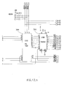
- Fig. 1 is a block diagram illustration of the interaction of an emergency mobilization apparatus constructed and operative in accordance with a preferred embodiment of the present invention with a telephony environment;
- Fig. 2 is a pictorial illustration of the geographical distribution of elements of an emergency mobilization system in conjunction with a single alert network, constructed and operative in accordance with a preferred embodiment of the invention;
- Fig. 3 is a diagram of a subscriber list and a plurality of methods of accessing further subscribers if the main subscriber is unavailable, useful in the system of Figs. 1 and 2;
- Fig. 4 is a pictorial illustration of the geographical distribution of elements of an emergency mobilization system in conjunction with a plurality of national alert networks, useful in the sytem of Figs. 1 and 2;
- Fig. 5 is a block diagram illustration of the mobilization apparatus of Fig. 1;
- Fig. 6 is a block diagram illustration of a line subsystem forming part of the system of Fig. 5;
- Fig. 7 is a block diagram illustration of a control subsystem forming part of the apparatus of Fig. 5;
- Fig. 8 is a block diagram illustration of a mass storage subsystem forming part of the apparatus of Fig. 5;
- Fig. 9 is a block diagram illustration of MTU circuitry forming part of the line subsystem shown in Fig. 6;
- Fig. 10 is a block diagram illustration of SPU circuitry forming part of the line subsystem shown in Fig. 6;
- Figs. 11 and 12 together define a schematic illustration of a preferred embodiment of SPU circuitry illustrated in Fig. 10;
- Figs. 13 - 16 together define a schematic illustration of a preferred embodiment of the MTU circuitry illustrated in Fig. 9;
- Fig. 17 is a block diagram illustration of TIU circuitry employed in the apparatus of Fig. 6;
- Figs. 18-21 are schematic illustrations of the TIU circuitry shown in Fig. 17;
- Figs. 22-40 are flow chart representations de-scribing the man/machine interface of the system of the present invention;
- Fig. 41 is a schematic illustration of a facsimile processing unit (FPU) constructed and operative in accordance with a preferred embodiment of the present invention; and
- Fig. 42 is a schematic illustration of line control unit circuitry (LCU) constructed and operative in accordance with a preferred embodiment of the present invention.
- Reference is made to Figs. 1 and 2 which illustrate a number of elements of the emergency mobilization system of the present invention. The emergency mobilization system comprises a multiplicity of
mobilization apparatus 1 each in telephonic communication with at least onepublic telephone switch 2. Additionally, the emergency mobilization system of the present invention typically operates in conjunction with at least one alert network which comprises the hierarchy of people to be mobilized. - When an emergency mobilization is required, an initator in an alert network control center 3 (Fig. 2) responsible for the mobilization dials the
mobilization apparatus 1 corresponding to thatcontrol center 3, creates a mobilization message, and instructs theapparatus 1 to perform a specific mobilization procedure. The initiator is a preliminary message sender; other mobilization personnel can create and send mobilization messages, as will be described hereinbelow. - A mobilization procedure typically is performed by mobilizing personnel who are identified on a mobilization list. To that end, the
mobilization apparatus 1 typically has stored in it a number of previously defined lists of personnel to be mobilized. The personnel to be mobilized will be known hereinafter as 'recipients'. Recipients are divided into two classes, subscribers, for each whom there is defined in apparatus 1 a private profile record and optionally, a private mailbox, and non-subscribers whose name and telephone numbers at which they can be reached are recorded on the mobilization list. - The private profile record typically comprises definitions of private parameters, such as an address and a plurality of telephone numbers, at which the subscriber can be reached. The subscriber's private mailbox is defined as a storage place in
apparatus 1 which typically stores arriving messages. - The mobilization list is typically created and modified via a console which may be an element of
mobilization apparatus 1, via a host computer connected tomobilization apparatus 1 or via a telephone. The mobilization list, or lists, may be created before the moment of the emergency and stored within themobilization apparatus 1. Alternatively, it may be created at the time of initiation of the mobilization. - The mobilization fist may comprise a record for a single recipient or it may comprise a plurality of records, one per a plurality of recipients. Additionally, the recipients may be subscribers and/or non-subscribers.
- Upon notification of a mobilization,
mobilization apparatus 1 dials to each of the recipients on the mobilization list, via thepublic telephone switches 2 in its region. The recipient may receive the phone call either at aprivate telephone 4, apublic telephone 6, acellular phone 8 via acellular telephone switch 9, via apager 11, or via any other suitable telephonic means. - For a non-subscriber recipient, the
mobilization apparatus 1 plays the mobilization message, typically twice, when someone at the telephone number of the non-subscriber responds to the phone call. If the person answering the telephone is not the non-subsciber, it is expected that that person will transmit the mobilization message to the non-subscriber. - For subscriber recipients,
mobilization apparatus 1 typically sends the mobilization message to each subscriber's mailbox.Apparatus 1 dials each subscriber and plays a predefined notification message which notifies the subscriber to access his mailbox. If desired by the recipient, the notification can be made repeatedly, typically until the subscriber accesses his mailbox. The mobilization apparatus plays the notification message to whom- ever picks up the telephone. If the subscriber is the one to pick up the telephone, the subscriber can immediately identify himself to the system and receive the mobilization message. If somebody else picked up the telephone and then ntoified the subscriber, the subscriber can dial to the system, identify himself and receive the mobilization message. This method of sending messages enhances the confidentiality of the mobilization and enables the sender to create detailed messages. - The amount of time between attempts to notify a subscriber, or to access a non-subscriber, as well as the number of such attempts is typically defined according to a predefined plan and is a function of the dial result, such as busy, no answer, etc., the number of tries previously attempted, and of the priority given to the notification or mobilization message, respectively. The retry periodicity may be a function of the number of previous unsuccessful attempts.
- The mobilization message may have been recorded some time before the start of the mobilization or a sender may record it immediately before sending it.
- The
mobilization apparatus 1 typically is capable of concurrently and asynchronously accessing multiple, typically 32, recipients via the at least onetelephone switch 2.Apparatus 1 typically will play the same mobilization message to each of the multiple recipients. Alternatively, a multiplicity of different messages can be played. In either case, for each recipient, the message is played starting from the beginning of the message. - Upon accessing a recipient,
mobilization apparatus 1 may request an acknowledgement of receipt of the message. The acknowledgement typically comprises the recording of a vocal reply or the entering of a code, either via pulse or DTMF dialling, or via speech recognition. Any unreceived messages are returned to the sender after a predetermined number of retries have occurred or a predetermined amount of time has elapsed. - In accordance with a preferred embodiment of the present invention, each recipient is associated with a backup recipient who will receive his messages if he does not answer within the predetermined amount of time. This is known as cascading and it is typically organized by having each recipient define who his backup recipient is.
- The cascading can be organized in a number of ways, as shown in Fig. 3. The recipients can be serially cascaded, as shown by (a), such that the
apparatus 1 first attempts to access amain recipient 13. Ifmain recipient 13 is unavailable, theapparatus 1 attempts to access abackup recipient 15. If thebackup recipient 15 is unavailable, theapparatus 1 returns a message to the sender indicating its inability to access anyone. - Alternatively, the serially cascading can be longer, as shown in (b).
- Should a person organizing the cascading require that someone successfully receive the message, and thus, be mobilized, the cascading is typically organized in a loop as shown in (c) where
apparatus 1first dials recipient 13, thenrecipient 15 and thenrecipient 17. If none of them respond, thenapparatus 1retries recipient 13 and so on until a reply is received. - Finally, the recipients can be organized in a tree structure, as shown in (d). In the example shown,
recipients recipient 25 who, in turn, is backed up byrecipient 29.Recipient 23 is backed up byrecipient 27 who is also backed up byrecipient 29. A loop can be included, as shown betweenrecipients - The mobilization list can be utilized as a mailing list, where the message is sent to all recipients.
Apparatus 1 notifies the sender of recipients which received and those who did not receive the message. Alternatively, the mobilization list can be utilized as a locating list where the sender requires that the message be received by a predetermined number of recipients listed on the mobilization list. Typically, once the predetermined number of recipients have responded,mobilization apparatus 1 no longer attempts to mobilize the remaining personnel on the list, if any exist. - Since each
apparatus 1 typically only accesses recipients located in the area near its location, the originally notifiedapparatus 1 may additionally notifyother apparatus 1 to send the mobilization message to recipients in their areas. Moreover, theapparatus 1 can be organized into a network covering a large area, in order to effect the mobilization of a large population. Additionally, by spreading the mobilization activity among a multiplicity ofregional mobilization apparatus 1, the number of long-dis- tance telephone calls is reduced. - Fig. 2 illustrates an example network of
apparatus 1. The network comprises a plurality ofapparatus 1 distributed throughout a given region, typically of a state or country, where eachapparatus 1 serves the geographical region in which it is located. Additionally, the at least one alert network comprises the alertnetwork control center 3, a multiplicity of regional control centers 31 and a plurality of local control centers 33. Eachlocal control center 33 is responsible for overseeing the mobilization occurring within a small geographic location and for reporting to aregional control center 31. Eachregional control center 31 receives information as to the status of the mobilization within its region and reports that information to the alertnetwork control center 3, which is responsible for the overall mobilization. - As mentioned hereinabove, the mobilization is typically initiated from the alert
network control center 3 which dials themobilization apparatus 1 assigned to it, marked 1A on Fig. 2.Apparatus 1A is typically theapparatus 1 which is closest to alertnetwork control center 3. -
Apparatus 1A then dials theother apparatus 1 which service the alert network, in accordance with instructions from the alertnetwork control center 3, and transmits to them information regarding the current emergency mobilization, such as the message to send, the specific mobilization list or lists to use, etc. - Each of the
apparatus 1 which receives mobilization instructions, includingapparatus 1A, performs the mobilization procedure described hereinabove. Mobilizations are typically performed hierarchically, beginning with mobilization of personnel with state-wide or national responsibilities, proceeding through mobilization of personnel with regional responsibilities and through mobilization of personnel with local responsibilites. The mobilization typically terminates with mobilization of the required personnel. Each person mobilized is called by theapparatus 1 located nearest to his home and/or place of work. - If the mobilization requires personnel with certain skills, then the initiator selects, or creates, a mobilization list of those personnel. If only a few of the personnel with the required skills are needed,
apparatus 1 will then use the list as a locating list and will mobilize the required number of people. If the personnel with the skills are located in a number of regions, then one of theapparatus 1 will be assigned the job of mobilizing them, thus requiring it to mobilize some people outside of its region. - In order to ensure that the mobilization is proceeding properly, controllers in each
local control center 33 dial theirrespective apparatus 1 and receive reports from theapparatus 1 on the status of the mobilization procedure (e.g. number of acknowledgements, the acknowledgements themselves, a list of people unsuccessfully contacted, etc). They then can instruct theapparatus 1 assigned to them with additional instructions, such as the sending of new mobilization messages or the mobilization of a new group of people. Additionally, the local controllers report to theregional control center 31 typically by sending messages from theirapparatus 1 to mailboxes of the regional controllers in theapparatus 1 assigned to theregional control center 31. - The reports can be received via a telephone, via a facsimile machine, via a printer or via a display apparatus connected to a host computer.
- The
regional control center 31 receives status reports from a plurality of local controllers. Similarly to the local controllers, the regional controllers can issue additional mobilization instructions to theapparatus 1 assigned to them and they can report the status of the regional mobilization to the alertnetwork control center 3. They can also send, messages to the local controllers with instructions concerning additional mobilizations to perform or with other information concerning the emergency mobilization. - The alert
network control center 3 receives reports from the regional controllers viaapparatus 1A. It additionally can request reports from appara- tus 1A describing the status of the mobilization of the personnel in the local area nearcontrol center 3. However, typically, there is alocal control center 33 assigned toapparatus 1 A, which receives the status reports fromapparatus 1 A and reports the results to theregional control center 31 who then reports to alertnetwork control center 3. - In accordance with a preferred embodiment of the present invention, each
apparatus 1 additionally stores the mobilization lists and other information concerning the recipients of at least oneneighboring apparatus 1. This provides redundancy in the mobilization system of the present invention and ensures that a mobilization can be performed even if a portion of theapparatus 1 and/or the telephony environment is not functioning. Additionally, for redundancy purposes, eachapparatus 1 is atwin apparatus 1 to ensure that if one of twins is not functioning, the other one is operative. - In accordance with a preferred embodiment of the present invention, a plurality of independent alert networks can typically be defined over the network of
apparatus 1, as illustrated in Fig. 4. For example, if the network of Fig. 4 belonged to a state, the state may choose to utilize it to define independent alert networks for the state police, the army, the reserves, local fire and police departments, and for hospitals. Each organization can define multiple alert networks, typically ranging from total mobilization to partial mobilization, such as a skeleton mobilization. - With multiple alert networks, mobilization of any organization can be performed in stages, if necessary. It can begin with a skeleton mobilization and then proceed through a partial mobilization to a full mobilization. A staggered mobilization, such as is described hereinabove, can be performed manually, by dialling the
apparatus 1 A each time a different level of mobilization is required and at that time, instructingapparatus 1 A as to which mobilization list to use, or it can be performed automatically, by assigning a specific time when a mobilization list is to be used or by assigning priorities to the messages sent by the different mobilization lists. - The automatic priority mobilization will be performed by allocating the entirety of the resources of the network of
apparatus 1 to the mobilization lists having the highest priority. As more and more of the highest priority personnel have been contacted, the network allocates more and more resources to the next highest priority mobilization list. The process proceeds until all personnel on the mobilization lists have been contacted. - It should be noted that the mobilization procedure described hereinabove pertains to a multi- regional emergency mobilization. It is also possible to perform a local mobilization utilizing one or a few of the
apparatus 1. In the local case, the local or regional controllers are responsible for the mobilization and there is no need for them to report to an alert network control center. - It will be appreciated by those skilled in the art that the detailed control of the mobilization process provided by the system of the present invention enables-the mobilizing organization to employ fewer people to perform the mobilization while being continually aware of the status of the mobilization. This enables the mobilizing organization to make informed decisions about other aspects of the mobilization, such as transportation of those mobilized to their respective locations for duty.
- The emergency mobilization apparatus of the present invention supports a message file system and receives and stores voice and image records in subscriber's mailboxes.
- The
mobilization apparatus 1 of the present invention is capable of informing a subscriber when a voice message or a facsimile record, has been placed in his mailbox. As mentioned hereinabove, theapparatus 1 informs the subscriber by calling him over the telephone or by any other suitable technique. - The apparatus, using any DTMF telephone or DTMF acoustic dialler, scans the subscriber's mailbox for messages which are either voice messages or facsimile records. The subscriber can then hear or view his messages, delete or keep them, reply to the sender, or forward them to another subscriber, while optionally adding annotation.
- The subscriber can also forward his voice or facsimile messages to any other subscriber's mailbox anywhere over the telephone network via a telephone, a specially equipped personal computer or a facsimile system. The user can also retrieve the facsimile message immediately at a facsimile machine or at a specially equipped PC connected to his telephone line. He can control both transmission and retrieval of the facsimile message from his telephone keypad. Equipment for suitable adaptation of a PC is available from TITN Inc. and GAMALINK both of the U.S.A.
- As noted above, the
apparatus 1 supports the addition of a voice annotation to a facsimile record and linking of facsimile records into multirecord facsimile files. - Any subscriber, can create and send a voice message or a facsimile record to any telephone number or subscriber. Any non-subscriber may create and send a voice message or a facsimile record to any subscriber.
- Voice or facsimile records may be sent to a subscriber's mailbox by specifying his ID or extension number within an office and to a facsimile system (or specially equipped PC) by specifying its extension number within an office. Voice or facsimile records may be sent to a non-subscriber's facsimile by specifying its telephone number as well as to a list of subscribers, non-subscribers, and facsimile systems.
- Notification of the arrival of a voice or facsimile record to a subscriber's mailbox is preferably pro-' vided by a telephone call to a prespecified telephone number. Additionally, the notification may be made by activating a 'message waiting' indicator light on the subscriber's telephone, by activating a pager, or by display of the subscriber's mailbox identification code on a display or a printer.
- The entire interaction of the user (subscriber or non-subscriber) with the
apparatus 1 is typically carried out over the telephone. The user is guided with voice prompts and controls theapparatus 1 with DTMF keystrokes or with voice commands. Sending a facsimile to a subscriber and receiving it and programming the telephone number for notification are all done over the telephone. - A special option of the
apparatus 1 is the support of DID lines with associated subscribers' mailboxes. The user may call such an appropriate DID number to send or receive a voice message or facsimile. This eliminates the need for DTMF telephone sets. - The emergency mobilization apparatus of the present invention typically supports up to 32 lines of voice where, of those 32 lines, 20 lines may support facsimile data.
- Reference is now made to Fig. 5, which illustrates in block diagram form, the
mobilization apparatus 1 constructed and operative in accordance with a preferred embodiment of the present invention. Theapparatus 1 comprises acontrol subsystem 10 which is coupled to one or moremass storage subsystems 12 via aSASI bus 14. Thecontrol subsystem 10 is also coupled to a host computer (not shown) via anRS 232, Ethernet link (not shown) or an X.25network 18. The X.25network 18 additionally allows eachapparatus 1 to communicate withother apparatus 1.Control subsystem 10 is also coupled to apublic telephone switch 2 for communication with telephonic environments. -
Control subsystem 10 is coupled via one or more LBX busses 32 to a plurality ofline subsystems 34, each of which is adapted to interface with apublic telephone switch 2 as well as with telephones and facsimile machines, directly or via a central telephone office. - Reference is now made to Fig. 6, which illustrates, in block diagram form, a
line subsystem 34. The line subsystem comprises anMTU interface card 50, which is described hereinbelow in connection with Fig. 9, and which is connected to the control subsystem via the LBX bus 32 (Fig. 5). TheMTU interface card 50 is coupled via anextender card 52 to a sub LBXparallel bus 54 and to a PCM highwayserial bus 56. A plurality of signal processing units (SPU) 58, and optionally, a facsimile processing unit (FPU) 57, are coupled to thebusses PCM highway bus 56 and are connected to telephone lines via an RJIIC connection. - Reference is now made to Fig. 7, which illustrates, in block diagram form, the
control subsystem 10 of Fig. 5. Thecontrol subsystem 10 comprises two line CPUs (LCU) 70, such as anESBC 86 manufactured by the present applicants/assignees and illustrated in detail in Fig. 42. TheLCU 70 is preferably similar to a combination of the ISBC 186/03 of Intel and a memory, such as an Intel SBC12 CX memory. EachLCU 70 is coupled aline subsystem 34 via anLBX bus 32. - The
LCUs 70 are connected to amultibus 74. Also connected to multibus 74 are amass storage controller 76, coupled viaSASI bus 14 to themass storage subsystem 12, a main CPU (MCU) 80, such as anSBC 286/14 of Intel, ahost computer interface 82, such as an Intel SBC 544, an optional ethernet interface (not shown), such as an Intel SBC 552, and an X.25interface 86, such as an Intel SBC 188/56. A preferred software object listing for the EPROM of theMCU 80, when embodied in anIntel 286/14 is attached hereto as Software Annex E. - Reference is now made to Fig. 8, which illustrates the
mass storage subsystem 12. It is seen thatsubsystem 12 comprises a primarymass storage unit 90 including a plurality ofcontrollers 92, such as OMTI 5200 cards, each of which operates a pair ofdisk drives floppy drive 98. -
Subsystem 12 also typically comprises a secondarymass storage unit 106 which is similar tounit 90 except that it typically comprises at least oneadditional disk drive 108, operated by aseparate controller 110.PSU circuits - Reference is now made to Fig. 9, which is a block diagram illustration of MTU circuitry forming part of the line subsystem shown in Fig. 6. Reference is also made to Figs. 13-16 which are schematic illustrations of the circuitry of Fig. 9. The general function of the MTU circuitry is to provide an interface between the
LBX bus 32 and the subLBXparallel bus 54 enabling a LCU 70 (Fig. 7) to access the SPU circuits 58 (Fig. 6). In addition the MTU circuitry generates the necessary timing signals for providing control of the operation of theTIU circuits 60. - Address bus signals ABO - AB19, received along the LBX bus, are processed in the following manner: Signals ABO, AB10 -AB19 are fed to a
line receiver 200 which shapes the signals and outputs to anaddress decoder 202, which generates timing signals BDSEL, DSPCS and IOSEL. Timing signal IOSEL is employed to gate the access of theLCU 70 to theMTU circuitry 50. Timing signal DSPCS is employed to gate the access of theLCU 70 to theSPU circuits 58. Timing signal BDSEL is employed to gate timing generation circuitry 204 and 206. - Address signals ABO - AB16 supplied from
LBX bus 32 are supplied to linedrivers LA 16 to the sub LBXparallel bus 54. - Buffered address signals BADO, BAD10 and BAD11 from
line receiver 200 and timing signal IOSEL are supplied to anaddress decoder 216, which provides chip selection and initialization logic functions. - Data signals LDO - LD15 from
LBX bus 32 are coupled totransceivers reference numeral 217. The transceivers, which operate in both directions, shape and buffer the signals, and are are also coupled to subLBX data signals DO - D15.Data transceiver 220 is employed to provide a swapping operation for a double 8 bit transfer by a 16 bit bus. The operations oftransceivers circuitry 224. - The operation of
timing circuitry 224 is described hereinbelow: Timing signals BDSEL, STDSTB, LBHEN and BADO are fed totiming circuitry 224, anaddress decoder 226 andlogic gates - A
real time clock 232 supplies real time information (time and date) to theLCU 70, which accessesclock 232 using timing and address signals LA1 - LA4, DLWT/, DLRD/ and data bus signals DO - D3. Theclock 232 receives electrical power from a power supply back upcircuitry 234. -
Status input circuitry 236 provides conversion of analog signals from the subLBX bus to digital signals that can be read by theLCU 70 and includes a line receiver 238. - Wait state generator and
delay circuitry 240 includes shift register 204 and 206flip flops decoder 268. Gating signals ADSTB/ and DSTB are buffered by aline receiver 270 which outputs a buffered signal BDSTB to flipflop 266 and a buffered signal BADSTB/ to flipflop 264 via agate 272. - A clock signal CLK8HZ together with gating signals BLSEL, DSPCS and IOSEL are supplied to shift registers 204 and 206 which output timing signals DLDSTB, DLWT/, LACK/. These timing signals are delayed versions of the corresponding inputs to the shift registers 204 and 206 and are used to gate input-ouput operations of the rest of the circuitry.
- The
MTU circuitry 50 also includes timing circuitry for the the TIU andSPU circuitry oscillator 280, which outputs a 16 MHZ clock signal todivider circuitry 282, which includescounters timing logic circuitry 296, which comprises ashift register 298 and flipflops logic circuitry 296 anddivider circuitry 282 are supplied toline driver circuitry 304 which outputs the following timing signals to the subLBx bus 54: SYNC256, PCNCK, CLK16, Q3SH and SINC64. - Reference is now made to Fig. 10, which is a block diagram illustration of SPU circuitry forming part of the line subsystem shown in Fig. 6. Reference is also made to Figs. 11 and 12 which are schematic illustrations of the circuitry of Fig. 10.
- The general functions of the SPU circuitry will now be set forth:
- A. Conversion of a 64 kbs PCM signal from the
TIU circuitry 60 into 32 kbs ADPCM data and vice versa. - B. Detection of ring signals in cooperation with the
TIU circuitry 60. - C. Detection of pulse dialing signals and, in cooperation with the TIU, detection of the DTMF dialing signals.
- D. Detection of signaling tones in cooperation with the
TIU circuitry 60. - E. Voice energy calculation for automatic gain control and pause compression.
- F. Control of output gain via the
TIU circuitry 60. - The SPU circuitry of Fig. 10 comprises interface circuitry indicated generally by reference numerals 350 and 351 in addition to digital
signal processing devices 352 and 354. Interface circuitry 350 provides switch bank based communication betweendevices 352 and 354 on the one hand andLCU 70 on the other hand viasubLBX bus 54. - The circuitry of Fig. 10 may also be adapted to provide fax modem functions.
- The operation of the switch bank based communication will now be described: At any given moment, the
LCU 70 can access RAM banks A or B, respectively indicated by reference numerals 356 and 358 via six of twelve 3-state transceivers 360, 362, 364 and 366 and 3-state buffers state buffers subLBx bus 54 and control signals CCS, SWR and CRD from adecoder 384 to the RAM banks A and B, while 3-state buffers NAB 12 fromaddress translation circuitry 394 and control signals NCS, SWR and NRD from parallel read- write logic circuitry 388 to RAM banks A and B. - Three-state transceivers 360, 362, 364 and 366 are used to switch data signals CDBO - CDB7 from
subLBX bus 54 and NDBO - NDB7 fromdevices 352 and 354 to the RAM banks A and B. - The switching operation is controlled by timing signals SW1 and SW2 from
decoder 384. Aline receiver 390 shapes control signals A1, DSTB, R/W, A13 - 16, and LES from thesubLBX bus 54.Line receiver 390 outputs corresponding buffered signals todecoder 384, which in turn, outputs control signals SW1, SW2 and ESW which are directed to the remainder of the SPU circuitry. - Sync counters 392 and address
translation circuitry 394 are employed to generate address signals NABO - NAB12. -
Timing circuitry 396, which comprisesflip flops logic gates devices 352 and 354. - Reference is now made to Fig. 17 which is a block diagram illustration of the TIU circuitry and to Figs. 18 - 21 which together are a schematic illustration of this circuitry. The general function of the TIU circuitry is to interface the store and forward system of the present invention to subscriber telephone lines. The TIU circuitry converts the analog signals on the subscriber telephone lines to digital form suitable for further processing by the
SPU circuits 58. Additionally the TIU circuitry controls the conventional telephone operations such as OFF HOOK/ON HOOK. - A subscriber telephone line is connected to an active hold and feed
circuit 450, to ring and current detectcircuit 452 and to atransformer 454. When the subscriber calls theapparatus 1, ring detectcircuit 452 converts the ringing signal into a logic level which is transferred to parallel toserial conversion circuits 456. These circuits transmit the converted signal through PCM highway 56 (Fig. 6) to the spin circuits for further processing. - When the
apparatus 1 answers the subscriber's call, it provides an OFF HOOK operation in the following manner: - A
relay 458 is switched on closing a current loop through the subscriber line andactive hold circuitry 460. Ring and current detectcircuitry 452 detects the current flow through the loop and supplies a digital indication to the parallel toserial converter 456, which, in turn, transmits data through thePCM highway 56 to theSPU circuitry 58. - Any audio signal coming from the telephone subscriber line is fed to
transformer 454 which provides DC isolation of 2/4wire conversion circuitry 462 from the subscriber telephone line, while permitting passage of the audio AC signals therethrough. The 2/4wire conversion circuitry 462 routes the incoming audio signal to aprogrammable gain amplifier 463 which amplifies the signal according to a digital code supplied by control latches 472. The amplified signal is fed to an analog to digital converter (codec) 464, which converts the analog signal into a PCM equivalent waveform. - This waveform is transmitted along
PCM highway 56 to theSPU circuitry 58 for compression and further processing. Theapparatus 1 outputs audio signals to the subscriber line using the following method: - PCM coded audio signals are transferred from the SPU circuitry through the
PCM highway 56 tocodec 464 which converts the signal to an analog waveform. This waveform is routed by the 2/4wire conversion circuitry 462 and through thetransformer 454 to the subscriber line. - The audio from the
transformer 454 is also fed to theDTMF receiver 468. This receiver detects DTMF dialing tones and converts them into 4 bit digital data. This data is coupled onto thePCM highway 56 and transmitted to theSPU circuitry 58 for further processing. - It is appreciated that the circuitry of Fig. 19 is identical to that of Fig. 18 and provides support for additional telephone subscriber line interfaces.
-
TIU circuitry 60 is controlled by gating and timing signals generated by timingcircuitry 470. Whenever the spin requires control of an operation such as OFF HOOK or OUTPUT GAIN SELECT, it issues, via thePCM highway 56, an appropriate digital code which is then latched ontoregisters 472 and then fed to the remainder of the circuitry, as shown in Figs 17 and 21. - An oscillator 406 (Fig. 11) generates a 16MHZ signal and, together with
counters 408 and flipflops devices 352 and 354 and alatch 414 which is used to driveindication LEDs 416. - Figures 22-40 are flow chart representations describing the man/machine interface of the emergency mobilization apparatus forming part of the present invention. In view of the fact that they are self-explanatory and in the interest of conciseness, no further explanation thereof is provided herein.
- It will be appreciated by persons skilled in the art that the present invention is not limited by what has been particularly shown and described hereinabove. Rather the scope of the present invention is defined only by the claims which follow:
Claims (38)
1. An emergency mobilization system comprising: a network of mobilization devices each comprising: means for producing messages; and means for transmitting at least one message by telephone to each of a plurality of recipient means each associated with at least one recipient.
2. An emergency mobilization system according to claim 1 and wherein said recipient means comprises at least one of facsimile machines, pagers, telephones, computers, and computer terminals connected to a host computer.
3. An emergency mobilization system according to claim 1 and wherein said means for transmitting comprises means for receiving acknowledgements of receipt of said messages from said recipients and indications of non-receipt of said messages.
4. An emergency mobilization system according to claim 3 and wherein said means for receiving acknowledgements comprises means for receiving vocal replies.
5. An emergency mobilization system according to claim 3 and wherein said means for receiving acknowledgements comprises means for receiving DTMF dialled codes.
6. An emergency mobilization system according to claim 1 and wherein said at least one message includes at least one of mobilization messages and notifications that a message awaits the recipient.
7. An emergency mobilization system according to claim 6 and wherein said means for transmitting comprises means for dialling to said recipient means and means for outputting said mobilization message to said at least one recipient only if said recipient means goes OFF-HOOK.
8. An emergency mobilization system according to claim 6 and wherein said means for transmitting comprises means for sending said mobilization message to mailboxes belonging to said recipients, means for dialling to said recipient means, means for outputting a notification to each recipient only if each recipient means goes OFF-HOOK and means for outputting said mobilization message only when a recipient identifies himself to said mailbox.
9. An emergency mobilization system according to claim 7 and wherein if said recipient means is OFF-HOOK, said means for dialling redials to said recipient means until either said recipient responds or a predetermined number of redials has elapsed.
10. An emergency mobilization system according to claim 8 and wherein if said recipient means remains ON-HOOK for a predetermined time, said means for dialling redials to said recipient means until either said recipient accesses his mailbox or a predetermined number of redials has elapsed.
11. An emergency mobilization system according to claim 9 and wherein said means for dialling redials to said recipient means in accordance with a predefined plan.
12. An emergency mobilization system according to claim 10 and wherein said means for dialling redials to said recipient means in accordance with a predefined plan.
13. An emergency mobilization system according to claim 11 and wherein said predefined plan states the number of redials and the time between the redials in accordance with the dial result, the number of previous redials, and with the priority attached to said mobilization message.
14. An emergency mobilization system according to claim 12 and wherein said predefined plan states the number of redials and the time between the redials in accordance with the dial result, the number of previous redials, and with the priority attached to said mobilization message.
15. An emergency mobilization system according to claim 1 and wherein each of said mobilization devices include means for defining a backup recipient for each recipient and wherein said backup recipient will receive said mobilization message if said recipient is unavailable.
16. An emergency mobilization system according to claim 8 and wherein said means for outputting is responsive to a subsequent call from a subscriber who identifies himself to the system.
17. An emergency mobilization system according to claim 1 and wherein each of said mobilization devices include means for creating and storing a plurality of mobilization lists wherein each of said mobilization lists is a list of at least one recipient to be mobilized.
18. An emergency mobilization system according to claim 17 and wherein said mobilization list comprises a locating list for mobilizing a first predefined number of recipients on said mobilization list who are successfully contacted.
19. An emergency mobilization system according to claim 17 and wherein said means for creating and storing comprise at least one of a telephone, a console attached to said mobilization device, and a host computer connected to said mobilization device.
20. An emergency mobilization system according to claim 6 and wherein said mobilization message comprises a prerecorded message.
21. An emergency mobilization system according to claim 6 and wherein said means for producing messages records said mobilization message shortly before the time of transmission of said mobilization message.
22. An emergency mobilization system according to claim 1 and wherein said means for transmitting concurrently and asynchronously send a multiplicity of copies of said messages on a multiplicity of separate telephone lines.
23. An emergency mobilization system according to claim 1 and wherein said means for transmitting concurrently and asynchronously sends a multiplicity of versions of said messages on a multiplicity of separate telephone lines.
24. An emergency mobilization system according to claim 1 and wherein each of said mobilization devices include means for providing information on the status of the mobilization via at least one of telephones, facsimile reports, printers, and communication with a host computer.
25. An emergency mobilization system according to claim 1 and wherein one of said mobilization devices in said network originates an emergency mobilization procedure and instructs a multiplicity of said mobilization devices in said network to perform the mobilization.
26. An emergency mobilization system according to claim 1 and wherein each of said mobilization devices include means for receiving a multiplicity of instruction inputs for selectably mobilizing a multiplicity of groups of recipient means within said plurality of recipient means.
27. An emergency mobilization system according to claim 1 and wherein each mobilization device is operative to mobilize recipient means located within a local region of said mobilization device.
28. An emergency mobilization system according to claim 1 and wherein for each of said mobilization devices in said network at least one backup mobilization device is defined wherein said backup mobilization device belongs to said network.
29. An emergency mobilization system according to claim 1 and wherein each of said mobilization devices in said network is a twin mobilization device.
30. An emergency mobilization system according to claim 1 and wherein initiation of a local mobilization procedure is performed on one of said mobilization devices in said network via any manner of telephone.
31. An emergency mobilization system according to claim 1 and wherein said means for producing messages comprises at least one of telephone apparatus, telephone apparatus in association with DTMF acoustic diallers, telephone apparatus in association with facsimile machines and telephone apparatus associated with computer apparatus.
32. An emergency mobilization system according to claim 1 also comprising means for providing a store and forward function.
33. An emergency mobilization system according to claim 32 and wherein the means for providing a store and forward function also comprises:
interconnect subsystem apparatus arranged to interconnect with telephone switching apparatus; a control subsystem for providing control instructions to the interconnect subsystem apparatus, including instructions for transmitting and receiving voice messages;
and mass storage subsystem apparatus coupled to the control subsystem for storing voice transmissions.
34. An emergency mobilization system according to claim 1 and wherein each mobilization device also comprises means for storing voice messages, images, and messages combining voice and images.
35. A method of mobilizing emergency personnel including the steps of:
instructing an originator mobilization device to perform a specified mobilization; and
instruction by said originator mobilization device to a plurality of mobilization devices belonging to a network each to mobilize a specific group of recipients.
36. A method of mobilizing emergency personnel according to claim 35 and wherein said step of instruction includes the steps of transmission of at least one message from one of said plurality of mobilization devices to each one of its respective specific group of recipients and of recording the success or failure to transmit said at least one message.
37. A method of mobilizing emergency personnel according to claim 36 and wherein said step of transmission of messages includes the steps of receiving an acknowledgement receipt from a multiplicity of said recipients and of recording said acknowledgement receipts.
38. A method of mobilizing emergency personnel according to claim 36 and also including the step of reporting the status of the mobilization.
Applications Claiming Priority (2)
| Application Number | Priority Date | Filing Date | Title |
|---|---|---|---|
| IL91922 | 1989-10-06 | ||
| IL9192289A IL91922A (en) | 1989-10-06 | 1989-10-06 | Emergency mobilization system |
Publications (2)
| Publication Number | Publication Date |
|---|---|
| EP0421912A2 true EP0421912A2 (en) | 1991-04-10 |
| EP0421912A3 EP0421912A3 (en) | 1993-06-23 |
Family
ID=11060459
Family Applications (1)
| Application Number | Title | Priority Date | Filing Date |
|---|---|---|---|
| EP19900630171 Withdrawn EP0421912A3 (en) | 1989-10-06 | 1990-10-04 | Emergency mobilization system |
Country Status (3)
| Country | Link |
|---|---|
| US (1) | US5448618A (en) |
| EP (1) | EP0421912A3 (en) |
| IL (1) | IL91922A (en) |
Families Citing this family (20)
| Publication number | Priority date | Publication date | Assignee | Title |
|---|---|---|---|---|
| US6112075A (en) * | 1994-11-07 | 2000-08-29 | Weiser; Douglas Diedrich | Method of communicating emergency warnings through an existing cellular communication network, and system for communicating such warnings |
| US6021177A (en) | 1995-06-29 | 2000-02-01 | Allport; Douglas C. | Community alarm/notification device, method and system |
| FI960986A (en) * | 1996-03-01 | 1997-09-02 | Nokia Telecommunications Oy | Allocation of emergency speech in a mobile communication system |
| US6018699A (en) * | 1996-06-04 | 2000-01-25 | Baron Services, Inc. | Systems and methods for distributing real-time site specific weather information |
| US6493633B2 (en) | 1996-06-04 | 2002-12-10 | Robert O. Baron, Sr. | Systems and methods for distributing real-time site specific weather information |
| US6236365B1 (en) | 1996-09-09 | 2001-05-22 | Tracbeam, Llc | Location of a mobile station using a plurality of commercial wireless infrastructures |
| GB2337386B (en) | 1996-09-09 | 2001-04-04 | Dennis J Dupray | Location of a mobile station |
| US9134398B2 (en) | 1996-09-09 | 2015-09-15 | Tracbeam Llc | Wireless location using network centric location estimators |
| US7339467B2 (en) * | 1999-06-11 | 2008-03-04 | At&T Delaware Intellectual Property, Inc. | Apparatus and method for providing weather and other alerts |
| US6329904B1 (en) * | 1999-06-11 | 2001-12-11 | Safety Through Cellular, Inc. | Apparatus and method for providing weather and other alerts |
| US6867688B2 (en) | 1999-06-11 | 2005-03-15 | Safety Through Cellular, Inc. | Apparatus and method for providing weather and other alerts |
| US9875492B2 (en) | 2001-05-22 | 2018-01-23 | Dennis J. Dupray | Real estate transaction system |
| US10641861B2 (en) | 2000-06-02 | 2020-05-05 | Dennis J. Dupray | Services and applications for a communications network |
| US10684350B2 (en) | 2000-06-02 | 2020-06-16 | Tracbeam Llc | Services and applications for a communications network |
| US7565153B2 (en) | 2003-01-22 | 2009-07-21 | Cml Emergency Services Inc. | Method and system for delivery of location specific information |
| US8073422B2 (en) * | 2004-06-07 | 2011-12-06 | Cassidian Communications, Inc. | Satellite radio warning system and method |
| US7558558B2 (en) * | 2004-06-07 | 2009-07-07 | Cml Emergency Services Inc. | Automated mobile notification system |
| US20070288561A1 (en) * | 2006-05-23 | 2007-12-13 | Beckhusen Fred K | Hyperlink-based notification system method |
| NZ578654A (en) | 2007-01-22 | 2011-09-30 | Iam Technologies Llc | System and methods for providing a notification service for a dispatch of emergency services |
| US9538493B2 (en) | 2010-08-23 | 2017-01-03 | Finetrak, Llc | Locating a mobile station and applications therefor |
Citations (4)
| Publication number | Priority date | Publication date | Assignee | Title |
|---|---|---|---|---|
| GB2098833A (en) * | 1981-04-03 | 1982-11-24 | Altran Electronics | Public alert and assistance systems |
| US4450320A (en) * | 1981-10-26 | 1984-05-22 | Licentia Patent-Verwaltungs Gmbh | Dialing device with calling number and identification memory and method for using same |
| EP0278451A2 (en) * | 1987-02-09 | 1988-08-17 | Nec Corporation | Facsimile communication having call transfer means |
| DE3826243A1 (en) * | 1988-02-13 | 1989-08-24 | Japan Medical Information Netw | Centrally controlled information system, including the terminal used therefor |
Family Cites Families (41)
| Publication number | Priority date | Publication date | Assignee | Title |
|---|---|---|---|---|
| US3993862A (en) * | 1974-07-05 | 1976-11-23 | Lawrence Karr | Data compression |
| US4065642A (en) * | 1975-04-24 | 1977-12-27 | Mcclure William C | Message signaling and alerting system and method thereof |
| JPS5571343A (en) * | 1978-11-24 | 1980-05-29 | Hitachi Ltd | Inter-office trunk line space division and time division-type buffer memory dispersive arrangement picture sound transmission system |
| US4273961A (en) * | 1979-11-14 | 1981-06-16 | Gte Laboratories Incorporated | Apparatus for communicating with processing apparatus over a telephone network |
| US4371752A (en) * | 1979-11-26 | 1983-02-01 | Ecs Telecommunications, Inc. | Electronic audio communication system |
| US4347607A (en) * | 1980-05-09 | 1982-08-31 | Harris Corporation | Voice alarm signalling system |
| JPS574653A (en) * | 1980-06-12 | 1982-01-11 | Fujitsu Ltd | Transmitting system of facsimile picture information |
| JPS5738055A (en) * | 1980-08-19 | 1982-03-02 | Ricoh Co Ltd | Memory control circuit for storage exchange facsimile |
| US4447872A (en) * | 1980-10-20 | 1984-05-08 | Minnesota Mining And Manufacturing Company | Alarm data concentration and gathering system |
| JPS57119541A (en) * | 1981-01-19 | 1982-07-26 | Nec Corp | Retrieval system for communication state |
| JPS57119537A (en) * | 1981-01-19 | 1982-07-26 | Fujitsu Ltd | Facsimile communication system |
| JPS57192167A (en) * | 1981-05-20 | 1982-11-26 | Mitsubishi Electric Corp | Facsimile storage exchanger |
| US4547778A (en) * | 1981-06-09 | 1985-10-15 | Texas Instruments Incorporated | Method and apparatus for automatic distress call signal transmission |
| JPS58138148A (en) * | 1982-02-12 | 1983-08-16 | Hitachi Ltd | Mail box index output system |
| JPS58138162A (en) * | 1982-02-12 | 1983-08-16 | Hitachi Ltd | Facsimile storage converting system |
| JPS58165452A (en) * | 1982-03-25 | 1983-09-30 | Nec Corp | Facsimile exchange system |
| JPS58175342A (en) * | 1982-04-07 | 1983-10-14 | Fujitsu Ltd | Data transmission controlling system |
| JPS58187055A (en) * | 1982-04-26 | 1983-11-01 | Nec Corp | Conference communication system |
| JPS5927664A (en) * | 1982-08-05 | 1984-02-14 | Canon Inc | Facsimile device |
| JPS5930352A (en) * | 1982-08-13 | 1984-02-17 | Nippon Telegr & Teleph Corp <Ntt> | Communication processing system of composite infomation |
| JPS5999846A (en) * | 1982-11-30 | 1984-06-08 | Nec Corp | Facsimile communication device |
| JPS59117845A (en) * | 1982-12-24 | 1984-07-07 | Fujitsu Ltd | Facsimile storage exchange |
| JPH0620211B2 (en) * | 1983-05-20 | 1994-03-16 | 株式会社東芝 | Mail service system |
| JPS6046647A (en) * | 1983-08-24 | 1985-03-13 | Fujitsu Ltd | Telegram service system |
| US4523055A (en) * | 1983-11-25 | 1985-06-11 | Pitney Bowes Inc. | Voice/text storage and retrieval system |
| JPS60119164A (en) * | 1983-11-30 | 1985-06-26 | Fujitsu Ltd | Message communication system |
| JPS60119161A (en) * | 1983-12-01 | 1985-06-26 | Nec Corp | Method for outputting autonomous message of exchange |
| JPS60134554A (en) * | 1983-12-22 | 1985-07-17 | Canon Inc | Facsimile equipment |
| JPS60197059A (en) * | 1984-03-21 | 1985-10-05 | Fuji Xerox Co Ltd | Facsimile equipment |
| US4696028A (en) * | 1984-03-26 | 1987-09-22 | Dytel Corporation | PBX Intercept and caller interactive attendant bypass system |
| JPS60248057A (en) * | 1984-05-24 | 1985-12-07 | Fujitsu Ltd | Voice storage exchange system |
| US4724538A (en) * | 1985-09-06 | 1988-02-09 | Comstock Group, Inc. | Emergency roadside telephone communications system |
| JPS62132464A (en) * | 1985-12-04 | 1987-06-15 | Nec Corp | Electronic mail system |
| US4837798A (en) * | 1986-06-02 | 1989-06-06 | American Telephone And Telegraph Company | Communication system having unified messaging |
| JPS6399463U (en) * | 1986-12-19 | 1988-06-28 | ||
| US4875038A (en) * | 1988-01-07 | 1989-10-17 | Motorola, Inc. | Frequency division multiplexed acknowledge back paging system |
| US4918722A (en) * | 1988-05-11 | 1990-04-17 | Brooktrout Technology, Inc. | Control of electronic information delivery |
| CA1333296C (en) * | 1988-11-15 | 1994-11-29 | Dawn Smith | Group emergency call system |
| US4922514A (en) * | 1988-12-29 | 1990-05-01 | Dictaphone Corporation | Method and apparatus for dispatching services |
| US5077788A (en) * | 1989-07-06 | 1991-12-31 | Taro, Inc. | System and method for processing telephone communication |
| US5109399A (en) * | 1989-08-18 | 1992-04-28 | Alamo City Technologies, Inc. | Emergency call locating system |
-
1989
- 1989-10-06 IL IL9192289A patent/IL91922A/en not_active IP Right Cessation
-
1990
- 1990-10-04 EP EP19900630171 patent/EP0421912A3/en not_active Withdrawn
-
1993
- 1993-01-05 US US08/000,575 patent/US5448618A/en not_active Expired - Fee Related
Patent Citations (4)
| Publication number | Priority date | Publication date | Assignee | Title |
|---|---|---|---|---|
| GB2098833A (en) * | 1981-04-03 | 1982-11-24 | Altran Electronics | Public alert and assistance systems |
| US4450320A (en) * | 1981-10-26 | 1984-05-22 | Licentia Patent-Verwaltungs Gmbh | Dialing device with calling number and identification memory and method for using same |
| EP0278451A2 (en) * | 1987-02-09 | 1988-08-17 | Nec Corporation | Facsimile communication having call transfer means |
| DE3826243A1 (en) * | 1988-02-13 | 1989-08-24 | Japan Medical Information Netw | Centrally controlled information system, including the terminal used therefor |
Non-Patent Citations (5)
| Title |
|---|
| COMPUTER COMMUNICATIONS vol. 9, no. 5, October 1986, GUILDFORD GB pages 227 - 233 TI MAUDE 'distribution list in an X.400 message handling system' * |
| ELECTRICAL COMMUNICATION vol. 62, no. 2, November 1988, BRUSSELS BE pages 168 - 173 G. CLEMENT ET AL. 'Message handling system DPX400' * |
| IEEE TRANSACTIONS ON SOFTWARE ENGINEERING vol. SE-13, no. 9, September 1987, NEW YORK US pages 1001 - 1009 G.ALMES ET AL. 'Edmas : An object-oriented , locally distributed mail system' * |
| ITC INTERNATIONAL TELETRAFFIC CONGRESS vol. 5, 1985, AMSTERDAM,NL pages 1017 - 1023 H.INAMORI ET AL. 'an automatically repeated call model in NTT public fascimile communication systems' * |
| THE 8TH INTERNATIONAL CONFERENCE ON DISTRIBUTED COMPUTING SYSTEMS 13 June 1988, SAN JOSE, US pages 402 - 409 W.HILAL ET AL. 'designing large electronic mail systems' * |
Also Published As
| Publication number | Publication date |
|---|---|
| US5448618A (en) | 1995-09-05 |
| IL91922A0 (en) | 1990-06-10 |
| IL91922A (en) | 1996-05-14 |
| EP0421912A3 (en) | 1993-06-23 |
Similar Documents
| Publication | Publication Date | Title |
|---|---|---|
| US5448618A (en) | Emergency mobilization system | |
| AU611974B2 (en) | Method and apparatus for visual indication of stored voice signals | |
| US5121421A (en) | Interactive telephone communication system for hearing-impaired person | |
| EP0211860B1 (en) | Integrated message service system | |
| US5461665A (en) | Voice processing system | |
| AU654963B2 (en) | Telephone paging system for connecting calling and paged parties | |
| CN1074883C (en) | Method and apparatus for facilitating the making of collect calls | |
| US4916726A (en) | Telephone answering service with integrated voice and textual message storage | |
| US4640991A (en) | Electronic audio communications systems network | |
| US4602129A (en) | Electronic audio communications system with versatile message delivery | |
| US4221933A (en) | Data storage and retrieval structure for a message storage system | |
| US5249221A (en) | Telephone answering system with call transfer | |
| JPH06217017A (en) | Automatic calling processing system | |
| US5761312A (en) | Enhanced individual intelligent communication platform for subscribers on a telephone system | |
| WO1991007041A1 (en) | Called person identification in telecommunication | |
| EP0106575A2 (en) | Electronic audio communication system with user controlled message address | |
| WO1992022164A1 (en) | Hunt and seek telephone system | |
| EP0336524B2 (en) | Electronic audio communication system with user controlled message address | |
| JPS6224761A (en) | Transfer telephone system | |
| US20020168056A1 (en) | Voice/data telecommunications system for use with standard telephone interface without a dedicated telephone line | |
| Kasson | The ROLM computerized branch exchange: An advanced digital PBX | |
| CA1207477A (en) | Electronic communication message system | |
| JPS6224756A (en) | Selective connection telephone system | |
| JPS6224762A (en) | Automatic telephone system | |
| JPS6240856A (en) | Intercepting system |
Legal Events
| Date | Code | Title | Description |
|---|---|---|---|
| PUAI | Public reference made under article 153(3) epc to a published international application that has entered the european phase |
Free format text: ORIGINAL CODE: 0009012 |
|
| AK | Designated contracting states |
Kind code of ref document: A2 Designated state(s): AT BE CH DE DK ES FR GB GR IT LI LU NL SE |
|
| PUAL | Search report despatched |
Free format text: ORIGINAL CODE: 0009013 |
|
| AK | Designated contracting states |
Kind code of ref document: A3 Designated state(s): AT BE CH DE DK ES FR GB GR IT LI LU NL SE |
|
| 17P | Request for examination filed |
Effective date: 19931223 |
|
| STAA | Information on the status of an ep patent application or granted ep patent |
Free format text: STATUS: THE APPLICATION HAS BEEN WITHDRAWN |
|
| 18W | Application withdrawn |
Withdrawal date: 19940307 |