EP0421492B1 - Production line for and method of processing pallet-mounted electric motor stators - Google Patents
Production line for and method of processing pallet-mounted electric motor stators Download PDFInfo
- Publication number
- EP0421492B1 EP0421492B1 EP90125434A EP90125434A EP0421492B1 EP 0421492 B1 EP0421492 B1 EP 0421492B1 EP 90125434 A EP90125434 A EP 90125434A EP 90125434 A EP90125434 A EP 90125434A EP 0421492 B1 EP0421492 B1 EP 0421492B1
- Authority
- EP
- European Patent Office
- Prior art keywords
- stator
- stators
- pallet
- production line
- working stations
- Prior art date
- Legal status (The legal status is an assumption and is not a legal conclusion. Google has not performed a legal analysis and makes no representation as to the accuracy of the status listed.)
- Expired - Lifetime
Links
Images

Classifications
-
- H—ELECTRICITY
- H02—GENERATION; CONVERSION OR DISTRIBUTION OF ELECTRIC POWER
- H02K—DYNAMO-ELECTRIC MACHINES
- H02K15/00—Methods or apparatus specially adapted for manufacturing, assembling, maintaining or repairing of dynamo-electric machines
-
- Y—GENERAL TAGGING OF NEW TECHNOLOGICAL DEVELOPMENTS; GENERAL TAGGING OF CROSS-SECTIONAL TECHNOLOGIES SPANNING OVER SEVERAL SECTIONS OF THE IPC; TECHNICAL SUBJECTS COVERED BY FORMER USPC CROSS-REFERENCE ART COLLECTIONS [XRACs] AND DIGESTS
- Y10—TECHNICAL SUBJECTS COVERED BY FORMER USPC
- Y10T—TECHNICAL SUBJECTS COVERED BY FORMER US CLASSIFICATION
- Y10T29/00—Metal working
- Y10T29/53—Means to assemble or disassemble
- Y10T29/5313—Means to assemble electrical device
- Y10T29/53143—Motor or generator
- Y10T29/53161—Motor or generator including deforming means
-
- Y—GENERAL TAGGING OF NEW TECHNOLOGICAL DEVELOPMENTS; GENERAL TAGGING OF CROSS-SECTIONAL TECHNOLOGIES SPANNING OVER SEVERAL SECTIONS OF THE IPC; TECHNICAL SUBJECTS COVERED BY FORMER USPC CROSS-REFERENCE ART COLLECTIONS [XRACs] AND DIGESTS
- Y10—TECHNICAL SUBJECTS COVERED BY FORMER USPC
- Y10T—TECHNICAL SUBJECTS COVERED BY FORMER US CLASSIFICATION
- Y10T29/00—Metal working
- Y10T29/53—Means to assemble or disassemble
- Y10T29/5313—Means to assemble electrical device
- Y10T29/53261—Means to align and advance work part
-
- Y—GENERAL TAGGING OF NEW TECHNOLOGICAL DEVELOPMENTS; GENERAL TAGGING OF CROSS-SECTIONAL TECHNOLOGIES SPANNING OVER SEVERAL SECTIONS OF THE IPC; TECHNICAL SUBJECTS COVERED BY FORMER USPC CROSS-REFERENCE ART COLLECTIONS [XRACs] AND DIGESTS
- Y10—TECHNICAL SUBJECTS COVERED BY FORMER USPC
- Y10T—TECHNICAL SUBJECTS COVERED BY FORMER US CLASSIFICATION
- Y10T29/00—Metal working
- Y10T29/53—Means to assemble or disassemble
- Y10T29/5313—Means to assemble electrical device
- Y10T29/53265—Means to assemble electrical device with work-holder for assembly
Definitions
- the invention relates to a production line for pallet-mounted electric motor stators.
- stators lie directly on pallets on conveyor belts which move along lines.
- the various working stations are provided at the sides of these lines. These stations include the stations for slot insulation, mounting the shoulders and mounting the terminals on them, winding formation, wire end termination, terminal soldering, coil baking, and stator electrical testing.
- the stators On reaching one of these stations, the stators must be removed from the conveyor belt and positioned in the working station, after which the stator is again returned to the line for feeding to the next station.
- Document GB-A-2145355 relates to an apparatus and method for the automatic production of armatures for small electric motors.
- the armatures are clamped in work piece holders and are moved to successive stations of the apparatus by a conveyor belt.
- the work piece holders are raised in relation to the conveyor belt by positioning a locking bolt and are held in the working position.
- the armatures are mounted on the work piece holders with vertical axis and the work piece holder is not provided with means arranged to temporarily receive the ends of wire windings.
- the invention provides a line in which the stators are mounted with their axis horizontal and perpendicular to the direction of travel of the line on cradle-shape portions of pallets which move with the conveyor belt.
- the pallet is raised together with the stator so that it can be positioned in relation to the machine which is to carry out the necessary work.
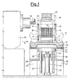
- Figure 1 is a cross-section of a transfer line for the transfer of pallets which carry stators mounted thereon with their axis extending in a horizontal direction, wherein said cross-section is made at a processing station and at respective devices for positioning the pallets in relation to said station.
- Figure 2 is a view in the direction of the arrow A of Fig. 1.
- Figure 1 and 2 show a stator 10 of conventional type, mounted, with its axis extending in a horizontal direction, on a cradle-shape portion of a cylindrical hollow body 11 anchored at its lower portion on a base 12.
- the base 12 and the body 11 form the pallet which slides on the belts 13 of the transfer line.
- Stator 10 is mounted on the body 11, at the side of which there are provided appendices 16 intended to ensure the temporary anchorage of the ends of the wires 17 after windings 18 have been formed on the slots of the stator.
- Figure 1 shows the station for forming the windings 18, which is disposed at the side of the line 13 and operates along a horizontal axis.
- a needle 19 is disposed eccentrically and is able to provide windings without the aid of the conventional forming shoes.
- This construction of the eccentric needle has formed the subject-matter of the nursery patent No. 1200443 of April 2, 1985, in the name of the present Applicant.
- stator 10 is disposed on the pallet, with its axis extending in a horizontal direction.
- stator 10 could have been disposed with its axis extending vertically on another pallet, in which case a simple device (not shown) would produce rotation and arrangement of the stator into the present position on the cylindrical hollow body 11.
- stator travels on the pallet along the line always keeping this position with the axis extending horizontally, and all the processing stations, and not only the winding station described herein, are arranged in such a manner as to able to work thereon in such position.
- stator working stations Since not all the stator working stations can be positioned at the level of the advancing stator, it is necessary to be able to raise the pallet with the stator on it vertically from the conveyor belt 13 in order to reach a position corresponding to the working station itself.
- the device which produces the vertical transfer of the pallet is formed, by way of example, by a cylinder 22 whose piston rod 23 is rigidly connected to a fork 24 provided with bars 25 which slide in guides 26 of a support 28 fixed to the frame 27 on which the conveyer belts 27 slide. Cylinder 22 also is rigidly connected to the support 28 screwed to the frame 27.
- cylinder 22 is actuated in the opposite direction and the pallet returns to rest on the conveyer belts 13 in order to be transferred into the succeeding station which usually is the termination station in which the ends of the wires 17 are manipulated for the definitive anchorage to the terminals of the stator and then the exceeding portions are cut away.
Description
- The invention relates to a production line for pallet-mounted electric motor stators.
- At the present time, stators lie directly on pallets on conveyor belts which move along lines. The various working stations are provided at the sides of these lines. These stations include the stations for slot insulation, mounting the shoulders and mounting the terminals on them, winding formation, wire end termination, terminal soldering, coil baking, and stator electrical testing.
- On reaching one of these stations, the stators must be removed from the conveyor belt and positioned in the working station, after which the stator is again returned to the line for feeding to the next station.
- This type of production cycle considerably penalizes productivity, as the stators have to be continuously transferred to and from the various working stations by respective members which remove them from the pallets on the belts, transport them to the station, return them to the pallets on the belts and position them thereon.
- The members, which are complicated, also penalize the line from an economic viewpoint.
- Document GB-A-2145355 relates to an apparatus and method for the automatic production of armatures for small electric motors. The armatures are clamped in work piece holders and are moved to successive stations of the apparatus by a conveyor belt. The work piece holders are raised in relation to the conveyor belt by positioning a locking bolt and are held in the working position.
- However, in this apparatus the armatures are mounted on the work piece holders with vertical axis and the work piece holder is not provided with means arranged to temporarily receive the ends of wire windings.
- The production lines for processing stators and armatures are, indeed, quite different from each other and the problems to be overcome in the two fields require different solutions.
- To obviate the drawback of the known production lines for electric motor stators, as above indicated, the invention provides a line in which the stators are mounted with their axis horizontal and perpendicular to the direction of travel of the line on cradle-shape portions of pallets which move with the conveyor belt. In certain stations, such as the winding formation and termination stations, the pallet is raised together with the stator so that it can be positioned in relation to the machine which is to carry out the necessary work. By this means, the idle times involved in transferring the stator to and from the various working stations can be considerably reduced.
- In certain stations these transfers are not required as the required work is carried out directly on the stator without removing the pallet from the belts.
- By this means, the idle times involved in transferring the stator to and from the various working stations can be considerably reduced, because in certain station these do not arise and in other stations it is simply a matter of raising the pallet on which the stator is fixed.
- In addition to increasing productivity, equipment costs and the complexity of the entire line is also reduced.
- The above and further objects which will be more apparent hereinafter are attained according to the invention by a production line for electric motor stators, as claimed in claim 1.
- An embodiment of the invention is described hereinafter by way of a non-limiting example with reference to the accompanying drawings in which:
- Figure 1 is a cross-section of a transfer line for the transfer of pallets which carry stators mounted thereon with their axis extending in a horizontal direction, wherein said cross-section is made at a processing station and at respective devices for positioning the pallets in relation to said station.
- Figure 2 is a view in the direction of the arrow A of Fig. 1.
- Figure 1 and 2 show a
stator 10 of conventional type, mounted, with its axis extending in a horizontal direction, on a cradle-shape portion of a cylindricalhollow body 11 anchored at its lower portion on abase 12. Thebase 12 and thebody 11 form the pallet which slides on thebelts 13 of the transfer line. -
Stator 10 is mounted on thebody 11, at the side of which there are providedappendices 16 intended to ensure the temporary anchorage of the ends of thewires 17 afterwindings 18 have been formed on the slots of the stator. - Figure 1 shows the station for forming the
windings 18, which is disposed at the side of theline 13 and operates along a horizontal axis. - In the embodiment shown diagrammatically in Fig. 1, a
needle 19 is disposed eccentrically and is able to provide windings without the aid of the conventional forming shoes. This construction of the eccentric needle has formed the subject-matter of the italian patent No. 1200443 of April 2, 1985, in the name of the present Applicant. - This technical solution and a second technical solution (not shown) with movable needles which has formed the subject-matter of the italian patent No. 1185206 of July 9, 1985, allows winding without the use of forming shoes. Therefore, they could advantageously be employed on the line forming the subject-matter of the present patent application, inasmuch as the use of forming shoes and, hence, conventional equipment for forming the windings on the stator, could render difficult the processing on stators anchored on pallets. However, suitable modifications of the configuration of the pallet could allow using
equipments 20 of a type different from the one shown in Fig. 1 or from the one which has been advantageously proposed by the Applicant, without departing from the scope of the present invention which absolutely does not aim to provide a method for forming the windings. - In known manner, when the windings are finished, the ends of the
wires 17 are temporarily anchored on side supports to thestator 10, which in this case are thepallet appendixes 16. - Thus, the
stator 10 is disposed on the pallet, with its axis extending in a horizontal direction. In a preceding upstream station it could have been disposed with its axis extending vertically on another pallet, in which case a simple device (not shown) would produce rotation and arrangement of the stator into the present position on the cylindricalhollow body 11. - In turn, the stator travels on the pallet along the line always keeping this position with the axis extending horizontally, and all the processing stations, and not only the winding station described herein, are arranged in such a manner as to able to work thereon in such position.
- Since not all the stator working stations can be positioned at the level of the advancing stator, it is necessary to be able to raise the pallet with the stator on it vertically from the
conveyor belt 13 in order to reach a position corresponding to the working station itself. - The device which produces the vertical transfer of the pallet is formed, by way of example, by a
cylinder 22 whosepiston rod 23 is rigidly connected to afork 24 provided withbars 25 which slide inguides 26 of asupport 28 fixed to theframe 27 on which theconveyer belts 27 slide.Cylinder 22 also is rigidly connected to thesupport 28 screwed to theframe 27. - The extention of the
rod 23 of thecylinder 22 causes thebars 25 to slide upwards with an initial restraining of thefork 24 into thecavity 29 of the pallet and its successive detachment from theconveyer belts 13 and transfer towards the winding needle 21 until reaching the position shown by dashed lines in Fig. 1, in which thestator 10 abuts at its upper part against a fixed V-shaped locking andreference striker 30. - After termination of the winding process,
cylinder 22 is actuated in the opposite direction and the pallet returns to rest on theconveyer belts 13 in order to be transferred into the succeeding station which usually is the termination station in which the ends of thewires 17 are manipulated for the definitive anchorage to the terminals of the stator and then the exceeding portions are cut away.
Claims (10)
- A production line for electric motor stators, which production line includes a plurality of stator-working stations (20) therein, and conveyor belt means (13) in proximity to the stator-working stations (20) for advancing the stators (10) from station to station; a plurality of pallets (12), individually supporting said stators (10) thereon during movement of said stators from station to station (20); characterized in that the stators (10) are processed while mounted on the respective pallets, (12), which pallets include a hollow body (11) having a cradle-shaped portion thereon, within which the stator (10) is arranged with its axis horizontal and perpendicular to the direction of travel of the belt means.
- A production line for electric motor stators according to claim 1 characterized in that appendices (16), extending from said pallet (12) are arranged to temporarily receive the ends of wire windings (17) formed on the stator (10) at one of the stator-working stations (20).
- A production line for electric motor stators according to claim 1 characterized in that in the stator-working stations (20) means (30) are provided for rigidly fixing the stators (10) on the pallets (12).
- A production line for electric motor stators according to claim 1 characterized in that mechanical means (22-29) are provided in proximity to the stator-working stations (20) for raising said pallets (12) together with the stators from the conveyor belt means (13) for translating said pallets so that the respective stators become disposed in positions corresponding with the working stations (20) located along the production line.
- A production line for electric motor stators, according to claim 4 characterized in that said mechanical means (22, 29) include a cylinder (22) positioned below the conveyor belt means (13), a stem (23) operated by the cylinder (22) and fork (24) rigidly connected to said stem (23) and engageable with said pallet (12) for translating the latter upon actuation of said cylinder (22).
- A line as claimed in claims 4 and 5 characterized in that the said fork (24) includes a pair of spaced arms (25), said conveyor belt means (13) includes a frame (28) having guides (26) therein, said arms (25) of the fork (24) slide in said guides (26) of the frame (28) of the conveyor belt means (13) and said cylinder (22) is rigidly connected to said frame (28).
- Method for processing electric motor stators along a production line including a plurality of stator-working stations (20) therein, and conveyor belt means (13) in proximity to the stator-working stations (20) for advancing the stators (10) from station to station; the method being characterized by the following steps:a) supporting each stator (10), with its axis horizontal, on a cradle-shape portion of a hollow body (11) of a respective pallet (12);b) positioning said pallet (12) in relation to the stator-working stations (20), with the mounted stator (10) having its axis horizontal and perpendicular to the direction of travel of the belt means;c) processing said stator (10) mounted on said pallet (12) in said stator-woking stations (20).
- Method according to claim 7 characterized in that at least during step c) the stator (10) is rigidly fixed to the pallet (12) by means (30).
- Method according to claim 7 characterized in that step b) is carried out by raising said pallet (12) with the stator from the conveyor belt means (13) for translating said pallet so that the respective stator (10) become disposed in position corresponding with the working stations (20).
- Method according to claim 7 characterized in that during step c) the ends of wire windings (17) formed on the stator (10) at one of the stator-working stations (20) are temporarily anchored to appendices (16) extending from said pallet (12).
Applications Claiming Priority (7)
| Application Number | Priority Date | Filing Date | Title |
|---|---|---|---|
| IT2153285 | 1985-07-11 | ||
| IT8521532A IT1207058B (en) | 1985-07-11 | 1985-07-11 | PROCESSING LINE FOR PALLETS-MOUNTED ELECTRIC DIMOTORS. |
| IT5395585U IT206713Z2 (en) | 1985-10-21 | 1985-10-21 | PROCESSING LINE FOR PALLETS-MOUNTED ELECTRIC DIMOTORS |
| IT5395485U IT206712Z2 (en) | 1985-10-21 | 1985-10-21 | PROCESSING LINE FOR PALLETS-MOUNTED ELECTRIC DIMOTORS |
| IT5395485U | 1985-10-21 | ||
| IT5395585U | 1985-10-21 | ||
| EP86200411A EP0209162B1 (en) | 1985-07-11 | 1986-03-14 | Production line for pallet mounted electric motor stators |
Related Parent Applications (1)
| Application Number | Title | Priority Date | Filing Date |
|---|---|---|---|
| EP86200411.6 Division | 1986-03-14 |
Publications (3)
| Publication Number | Publication Date |
|---|---|
| EP0421492A2 EP0421492A2 (en) | 1991-04-10 |
| EP0421492A3 EP0421492A3 (en) | 1992-04-15 |
| EP0421492B1 true EP0421492B1 (en) | 1994-07-20 |
Family
ID=27273188
Family Applications (2)
| Application Number | Title | Priority Date | Filing Date |
|---|---|---|---|
| EP86200411A Expired - Lifetime EP0209162B1 (en) | 1985-07-11 | 1986-03-14 | Production line for pallet mounted electric motor stators |
| EP90125434A Expired - Lifetime EP0421492B1 (en) | 1985-07-11 | 1986-03-14 | Production line for and method of processing pallet-mounted electric motor stators |
Family Applications Before (1)
| Application Number | Title | Priority Date | Filing Date |
|---|---|---|---|
| EP86200411A Expired - Lifetime EP0209162B1 (en) | 1985-07-11 | 1986-03-14 | Production line for pallet mounted electric motor stators |
Country Status (3)
| Country | Link |
|---|---|
| US (1) | US4713883A (en) |
| EP (2) | EP0209162B1 (en) |
| DE (2) | DE3680967D1 (en) |
Families Citing this family (27)
| Publication number | Priority date | Publication date | Assignee | Title |
|---|---|---|---|---|
| US5149000A (en) * | 1988-03-10 | 1992-09-22 | Axis S.P.A. | Machine for winding two-pole stators |
| IT1219093B (en) * | 1988-03-10 | 1990-04-24 | Axis Spa | WRAPPING MACHINE FOR BIPOLAR STATORS |
| IT1223829B (en) * | 1988-09-16 | 1990-09-29 | Axis Spa | LINE FOR THE PROCESSING OF DIFFERENT TYPES OF ARMATURES |
| US4856180A (en) * | 1988-12-06 | 1989-08-15 | General Electric Company | Method of terminating winding leads |
| US5240235A (en) * | 1988-12-16 | 1993-08-31 | Axis Usa, Inc. | Apparatus for making electric motor parts employing pallet with removable workpiece holder |
| IT1234229B (en) * | 1988-12-16 | 1992-05-06 | Axis Spa | METHODS AND EQUIPMENT FOR MAKING PARTS OF ELECTRIC MOTORS USING PALLETS WITH REMOVABLE SUPPORT OF THE WORKPIECE |
| US5362005A (en) * | 1989-02-06 | 1994-11-08 | Axis U.S.A., Inc. | Methods and apparatus for automated stator winding station set up |
| US5099568A (en) * | 1989-07-26 | 1992-03-31 | Axis Usa, Inc. | Methods for making stators for electric motors |
| US4994697A (en) * | 1989-07-26 | 1991-02-19 | Axis Usa, Inc. | Stator terminal board |
| US5239743A (en) * | 1989-07-26 | 1993-08-31 | Axis Usa, Inc. | Method for making stators for electric motors and the like |
| EP0468307A3 (en) * | 1990-07-27 | 1993-08-11 | Axis S.P.A. | Methods and apparatus for processing stators |
| US5137221A (en) * | 1990-10-04 | 1992-08-11 | Axis Usa, Inc. | Rapidly changeable chucks for holding stators in stator processing apparatus |
| CH681936A5 (en) * | 1991-02-01 | 1993-06-15 | Zihlmann Wickeltechnik Ag | Workpiece carrier for automatic assembly of electrical machine laminated stators - has frame on carriage coupled to feed conveyor with guides to hold plates forming the stator |
| US5337796A (en) * | 1991-09-30 | 1994-08-16 | Kao Corporation | Article transportation processing system |
| BR9600257A (en) * | 1995-01-31 | 1997-12-23 | Johnson & Johnson | Apparatus for supporting a wound coil core and a rear end of a wound wire and method for storing and retrieving a wound coil core and a rear end of a wound wire |
| IT1279951B1 (en) * | 1995-06-15 | 1997-12-23 | Oam Spa | PRODUCT TRANSFER UNIT |
| US5685413A (en) * | 1995-09-12 | 1997-11-11 | Odawara Automation, Inc. | Adjustable pallet for supporting work pieces |
| US5662317A (en) * | 1995-09-18 | 1997-09-02 | Globe Products Inc. | Pallet support assembly for use in manufacturing stators |
| US5658477A (en) * | 1995-11-22 | 1997-08-19 | Odawara Automation, Inc. | Method and apparatus for welding a stack of stator laminations |
| US5765274A (en) * | 1996-05-21 | 1998-06-16 | Globe Products Inc. | Stator manufacturing method |
| US5735219A (en) * | 1996-11-27 | 1998-04-07 | Odawara Automation, Inc. | Open base adjustable pallet for supporting work pieces |
| US6325199B1 (en) | 1998-10-05 | 2001-12-04 | Axis Usa, Inc. | Pallet conveyor apparatus |
| US6213285B1 (en) | 1998-11-25 | 2001-04-10 | International Business Machines Corporation | Method of indexing conveyor pallets at high speeds |
| EP1020347B1 (en) * | 1999-01-14 | 2007-06-27 | Nissan Motor Company, Limited | Method and apparatus for conveying works |
| KR100327000B1 (en) | 1999-08-05 | 2002-03-06 | 윤종용 | A lot production line of air conditioner |
| US6732971B2 (en) * | 2000-07-13 | 2004-05-11 | Axis U.S.A., Inc. | Apparatus and methods for winding and transferring dynamoelectric machine stators |
| US6789659B2 (en) | 2001-08-22 | 2004-09-14 | Odawara Automation, Inc. | Stator winding system and method with pallet on pallet arrangement |
Family Cites Families (13)
| Publication number | Priority date | Publication date | Assignee | Title |
|---|---|---|---|---|
| US3766617A (en) * | 1971-10-18 | 1973-10-23 | Motch Merryweather Machinery | Workpiece loader and unloader |
| GB1590919A (en) * | 1976-11-15 | 1981-06-10 | Axis Spa | Workpiece processing systems |
| US4151636A (en) * | 1977-12-05 | 1979-05-01 | General Electric Company | Injection shuttle system |
| US4106185A (en) * | 1977-06-13 | 1978-08-15 | General Electric Company | Motor manufacturing method, system and method, system and components |
| JPS54156102A (en) * | 1978-05-30 | 1979-12-08 | Matsushita Electric Ind Co Ltd | Method and machine of manufacturing stators of electrical machines |
| JPS5857063B2 (en) * | 1978-10-06 | 1983-12-17 | 株式会社日立製作所 | Transport jig for electrical work |
| DE2853103A1 (en) * | 1978-12-08 | 1979-12-13 | Karlsruhe Augsburg Iweka | TRANSPORT DEVICE FOR A PACKING MACHINE, ESPECIALLY FOR A TUBE FILLING AND SEALING MACHINE |
| IT1128041B (en) * | 1980-02-11 | 1986-05-28 | Pavesi Spa Off Mec | DEVICE AND PROCEDURE FOR THE INSERTION OF PRE-WINDED MASSES IN THE STATOR GROOVES OF DYNAMOELECTRIC MACHINES |
| CH652538A5 (en) * | 1981-01-29 | 1985-11-15 | Micafil Ag | DEVICE FOR CONNECTING THE WINDING ENDS TO THE TERMINALS OF STATORS OF ELECTRICAL MACHINES AND A METHOD FOR OPERATING THE SAME. |
| SU998080A2 (en) * | 1981-09-29 | 1983-02-23 | Всесоюзный Научно-Исследовательский И Проектно-Конструкторский Институт Технологии Электромашиностроения "Вниитэлектромаш" | Automatic line for heat assembling of electric motor rotors |
| US4464826A (en) * | 1982-07-26 | 1984-08-14 | General Electric Company | Method and apparatus for aligning laminations in a stator core |
| CH660819A5 (en) * | 1983-08-22 | 1987-06-15 | Micafil Ag | DEVICE FOR THE AUTOMATIC MANUFACTURING OF ANCHORS FOR SMALL ELECTRIC MOTORS AND A METHOD FOR OPERATING THE SAME. |
| DE3572096D1 (en) * | 1985-02-15 | 1989-09-07 | Micafil Ag | Device for the automatic manufacture of stators for electric motors |
-
1986
- 1986-03-14 EP EP86200411A patent/EP0209162B1/en not_active Expired - Lifetime
- 1986-03-14 DE DE8686200411T patent/DE3680967D1/en not_active Expired - Lifetime
- 1986-03-14 EP EP90125434A patent/EP0421492B1/en not_active Expired - Lifetime
- 1986-03-14 DE DE3689984T patent/DE3689984T2/en not_active Expired - Fee Related
- 1986-03-18 US US06/840,671 patent/US4713883A/en not_active Expired - Lifetime
Also Published As
| Publication number | Publication date |
|---|---|
| US4713883A (en) | 1987-12-22 |
| EP0209162A2 (en) | 1987-01-21 |
| EP0209162B1 (en) | 1991-08-21 |
| EP0421492A3 (en) | 1992-04-15 |
| EP0209162A3 (en) | 1987-05-13 |
| DE3689984T2 (en) | 1994-12-08 |
| EP0421492A2 (en) | 1991-04-10 |
| DE3680967D1 (en) | 1991-09-26 |
| DE3689984D1 (en) | 1994-08-25 |
Similar Documents
| Publication | Publication Date | Title |
|---|---|---|
| EP0421492B1 (en) | Production line for and method of processing pallet-mounted electric motor stators | |
| CN210192746U (en) | Automatic discharging and feeding and discharging integrated device | |
| US4718533A (en) | Transport installation for a production line having parallel-arranged processing stations | |
| EP0593087B1 (en) | Machine for winding two pole stators | |
| GB1571971A (en) | Method of manufacturing stators for electrical machines and apparatus employed therefor | |
| US4679312A (en) | Methods and apparatus for the automatic production of stators for electric motors | |
| CN112703665B (en) | Method for providing hairpin elements for windings of an electric machine | |
| US5494230A (en) | Method for loading and unloading workpieces | |
| CN209994249U (en) | Multi-station motor automatic winding machine | |
| US5145052A (en) | Apparatus for substantially simultaneously processing multiple electric motor parts | |
| US3878602A (en) | Method for forming windings on rotors of electric motors or the like | |
| JPH0648195U (en) | Supply posture correction device for continuous terminal supply mechanism | |
| WO1997042698A9 (en) | Stator winding method and apparatus | |
| WO1997042698A1 (en) | Stator winding method and apparatus | |
| CN211939767U (en) | Automatic press-fitting machine for motor rotor | |
| EP0206211B1 (en) | Method and apparatus for winding and inserting coils in a dynamoelectric machine stator core | |
| EP0209161A1 (en) | Device for transfering a pallet mounted electric motor armature to an armature winding formation station | |
| KR100253877B1 (en) | Axial type electronic component inserting method and apparatus | |
| US3099348A (en) | Apparatus for advancing like elongated finishing bars | |
| US5240044A (en) | Work piece carrier with auxiliary carrier for producing electric coils | |
| CN216829062U (en) | Coil feeding mechanism | |
| KR940008413B1 (en) | Manufacturing method and apparatus of armature for starting motor | |
| KR200145265Y1 (en) | Apparatus for supplying lead frame | |
| JPS6216047A (en) | Production line for motor stator mounted on pallet | |
| CN110601469B (en) | Multi-station motor automatic winding machine |
Legal Events
| Date | Code | Title | Description |
|---|---|---|---|
| PUAI | Public reference made under article 153(3) epc to a published international application that has entered the european phase |
Free format text: ORIGINAL CODE: 0009012 |
|
| AC | Divisional application: reference to earlier application |
Ref document number: 209162 Country of ref document: EP |
|
| AK | Designated contracting states |
Kind code of ref document: A2 Designated state(s): CH DE FR GB LI SE |
|
| PUAL | Search report despatched |
Free format text: ORIGINAL CODE: 0009013 |
|
| AK | Designated contracting states |
Kind code of ref document: A3 Designated state(s): CH DE FR GB LI SE |
|
| 17P | Request for examination filed |
Effective date: 19920612 |
|
| 17Q | First examination report despatched |
Effective date: 19930913 |
|
| GRAA | (expected) grant |
Free format text: ORIGINAL CODE: 0009210 |
|
| AC | Divisional application: reference to earlier application |
Ref document number: 209162 Country of ref document: EP |
|
| AK | Designated contracting states |
Kind code of ref document: B1 Designated state(s): CH DE FR GB LI SE |
|
| REF | Corresponds to: |
Ref document number: 3689984 Country of ref document: DE Date of ref document: 19940825 |
|
| PG25 | Lapsed in a contracting state [announced via postgrant information from national office to epo] |
Ref country code: SE Effective date: 19941020 |
|
| ET | Fr: translation filed | ||
| PLBE | No opposition filed within time limit |
Free format text: ORIGINAL CODE: 0009261 |
|
| STAA | Information on the status of an ep patent application or granted ep patent |
Free format text: STATUS: NO OPPOSITION FILED WITHIN TIME LIMIT |
|
| 26N | No opposition filed | ||
| REG | Reference to a national code |
Ref country code: GB Ref legal event code: IF02 |
|
| PGFP | Annual fee paid to national office [announced via postgrant information from national office to epo] |
Ref country code: GB Payment date: 20030227 Year of fee payment: 18 |
|
| PGFP | Annual fee paid to national office [announced via postgrant information from national office to epo] |
Ref country code: FR Payment date: 20030319 Year of fee payment: 18 |
|
| PGFP | Annual fee paid to national office [announced via postgrant information from national office to epo] |
Ref country code: CH Payment date: 20030325 Year of fee payment: 18 |
|
| PGFP | Annual fee paid to national office [announced via postgrant information from national office to epo] |
Ref country code: DE Payment date: 20030521 Year of fee payment: 18 |
|
| PG25 | Lapsed in a contracting state [announced via postgrant information from national office to epo] |
Ref country code: GB Free format text: LAPSE BECAUSE OF NON-PAYMENT OF DUE FEES Effective date: 20040314 |
|
| PG25 | Lapsed in a contracting state [announced via postgrant information from national office to epo] |
Ref country code: LI Free format text: LAPSE BECAUSE OF NON-PAYMENT OF DUE FEES Effective date: 20040331 Ref country code: CH Free format text: LAPSE BECAUSE OF NON-PAYMENT OF DUE FEES Effective date: 20040331 |
|
| PG25 | Lapsed in a contracting state [announced via postgrant information from national office to epo] |
Ref country code: DE Free format text: LAPSE BECAUSE OF NON-PAYMENT OF DUE FEES Effective date: 20041001 |
|
| GBPC | Gb: european patent ceased through non-payment of renewal fee |
Effective date: 20040314 |
|
| REG | Reference to a national code |
Ref country code: CH Ref legal event code: PL |
|
| PG25 | Lapsed in a contracting state [announced via postgrant information from national office to epo] |
Ref country code: FR Free format text: LAPSE BECAUSE OF NON-PAYMENT OF DUE FEES Effective date: 20041130 |
|
| REG | Reference to a national code |
Ref country code: FR Ref legal event code: ST |