EP0421096A2 - Electronic apparatus arrangement - Google Patents
Electronic apparatus arrangement Download PDFInfo
- Publication number
- EP0421096A2 EP0421096A2 EP90115492A EP90115492A EP0421096A2 EP 0421096 A2 EP0421096 A2 EP 0421096A2 EP 90115492 A EP90115492 A EP 90115492A EP 90115492 A EP90115492 A EP 90115492A EP 0421096 A2 EP0421096 A2 EP 0421096A2
- Authority
- EP
- European Patent Office
- Prior art keywords
- housing
- electronic device
- arrangement according
- device arrangement
- circuit board
- Prior art date
- Legal status (The legal status is an assumption and is not a legal conclusion. Google has not performed a legal analysis and makes no representation as to the accuracy of the status listed.)
- Withdrawn
Links
Images


Classifications
-
- H—ELECTRICITY
- H05—ELECTRIC TECHNIQUES NOT OTHERWISE PROVIDED FOR
- H05K—PRINTED CIRCUITS; CASINGS OR CONSTRUCTIONAL DETAILS OF ELECTRIC APPARATUS; MANUFACTURE OF ASSEMBLAGES OF ELECTRICAL COMPONENTS
- H05K7/00—Constructional details common to different types of electric apparatus
- H05K7/14—Mounting supporting structure in casing or on frame or rack
- H05K7/1422—Printed circuit boards receptacles, e.g. stacked structures, electronic circuit modules or box like frames
- H05K7/1424—Card cages
- H05K7/1425—Card cages of standardised dimensions, e.g. 19"-subrack
Definitions
- the invention relates to an electronic device arrangement for control panel or console installation with a jacket-like housing, one end opening of which can be closed by a closure panel, with a first printed circuit board arranged approximately parallel to the bottom surface of the housing and at least approximately vertically upward a further printed circuit board, possibly carrying electronic components, can be plugged on in an electrically connecting manner with the first printed circuit board, the first and the further printed circuit boards being able to be arranged on a printed circuit board holder, with plug connections which are electrically conductively connected to the first printed circuit board and can be connected to the lines leading to external units are.
- circuit board holder in the region of an edge of the front opening of the housing on the housing is pivotable about a pivot axis and is pivotable out of its mounting position about the pivot axis out of the housing. Due to the pivotability of the circuit board holder and the arrangement of the pivot axis in the region of the front opening of the housing, the circuit board holder can at least largely be pivoted out of the housing, so that all circuit boards are freely accessible. An installation and removal of other components is not necessary if a new assembly or re-assembly of the circuit boards he follows. Damage to other components is largely avoided.
- Such repositioning or refitting can take place without interrupting the operation of the device arrangement.
- circuit board holder is firmly connected to the closure panel and the circuit board holder and closure panel can be pivoted out of the housing about a common pivot axis. As a result, the construction effort is kept low and the assembly and disassembly of printed circuit boards is further simplified.
- the pivot axis preferably extends along the lower, approximately horizontal edge of the front opening of the housing, so that when the card holder is pivoted out, the closure panel is located under the circuit board holder and does not interfere.
- the plug connections are arranged on the closure panel in such a way that the area with the plug-in counterpart provided with the lines is directed toward the exterior of the housing, the external connections can remain connected when the circuit board holder and closure panel are folded out. You then simply swivel along with the sealing panel without any tensile or compressive load acting on the lines.
- a fan unit is arranged on the closure panel, through which the housing of one Cooling air flow through which air drawn in from the outside can flow.
- the fan unit is arranged on the inside of the closure panel, while a filter unit is arranged on the outside of the closure panel opposite the fan unit and air can be drawn in from the outside of the housing through the filter unit and a corresponding continuous recess in the connection panel by the fan unit .
- the filter unit can consist of a rigid, approximately bowl-shaped filter grill, in the shell of which a filter mat can be inserted in such a way that it is arranged between the filter grill and the continuous recess of the closure panel.
- the filter grill has one or more threaded holes into which fastening screws, which are preferably knurled screws, can be screwed through corresponding holes in the closure panel, the filter grill can be loosened and the filter mat replaced by simply loosening the knurled nuts. Since the threaded pins protrude into the housing, there are no components which protrude outwards from the housing and on which one could get caught.
- the closure panel In the closed state, the closure panel has an area which is approximately parallel to the front plane of the housing and which springs back into the interior of the housing on which the plug connections are arranged and if the recessed area also extends by approximately the length of a counterpart parallel to the plane of the housing, the counterparts do not protrude beyond the housing periphery. Loosening of the mating parts by unintentional touching is thus largely avoided. This is particularly the case when the cables come laterally from the plug-in counterparts.
- a channel results through which the lines can be routed to other external units without protruding from the housing.
- An area of the closure panel which extends approximately in the plane of the housing can adjoin the recessed area.
- the transition area between the recessed area and the area extending in the plane of the housing can be designed as a recessed grip recess in a practically recessed design.
- the closure panel is particularly easy to manufacture if it is formed from a sheet of approximately Z-shaped cross-section, one end leg of the recessed area, the other end leg of the area extending in the plane of the housing and the connecting web forms the recessed grip.
- a particularly favorable utilization of the available installation space is achieved in that the fan unit is arranged in the area of the closure panel which extends in the plane of the housing.
- the first printed circuit board can either be designed without active electronic components, or active electronic components can be arranged on the first printed circuit board.
- the housing is formed in an area with ventilation slots, between which and the aerator unit the circuit boards are arranged, so that the cooling air flow always sweeps along the circuit boards.
- the housing has an insertion area which is designed with insertion guides and has an insertion opening and into which electronic devices can be inserted to close the insertion opening, further units can be arranged in the housing in addition to the printed circuit boards.
- Plug contacts are preferably arranged in the region of the rear wall of the insertion opening, into which corresponding plug counterparts on the back of the electronic devices can be inserted in a contacting manner by inserting the electronic devices into the insertion opening. This results in simple assembly and disassembly of the other units.
- the electronic devices can be power supply modules and / or drives.
- plug contacts are connected to the first printed circuit board via electrical lines, a connection can be made in the region of the pivot axis so that this connection does not have to be released when the printed circuit board holder is pivoted out.
- the electronic device arrangement shown in the figures has a housing 1 which consists of sheet metal parts which are connected to one another in an electrically conductive manner, so that a shielding effect which satisfies the required interference protection is achieved.
- the lower area of the housing 1 has an end opening 2, which is closed by a closure panel 3 is lockable.
- the closure panel 3 consists of a sheet Z-shaped cross section.
- the lower end leg 4 extends backwards by a distance parallel to the front plane of the housing 1.
- the end leg 4 is articulated on the housing 1 and can be pivoted about a pivot axis S from the closed position shown with a solid line into the open position shown with a broken line.
- a circuit board holder 6 is firmly connected, on which a first circuit board 7, which extends in the closed position and extends approximately parallel to the bottom surface of the housing 1, is arranged, on which active electronic components 8 are arranged, and on which further circuit boards 9 are attached in an electrically connecting manner are. These further circuit boards are held in guides of the circuit board holder 6 and can be provided with electronic components.
- the circuit board holder 6 with the circuit boards 7 and 9 is pivoted at the same time, so that they are at least largely outside of the housing 1 in the open position and can be easily replaced or supplemented.
- plug connections 10 are arranged facing the housing exterior, which are connected via lines or conductor tracks to the first circuit board 7 and whose contact opening protrudes through a corresponding opening in the lower end leg 4.
- a plug counterpart 11 can be plugged onto it from the outside, which is provided with a lateral outlet of a line 12.
- the upper end leg 13 of the closure panel 3 extends approximately in the plane of the housing 1 and can be screwed onto the housing 1 at its free end with a screw 14.
- fan units 15 are fastened on the inside, the upper recesses 16 in the closure panel 3 and outside filter units 17 suck in air from the outside and blow through the housing for cooling the electronic components.
- the filter units 17 consist of a bowl-shaped filter grill 18, in the shell of which a filter mat 19 can be inserted such that it covers the recess 16.
- Threaded bores 20 are formed on the filter grill 18, into which knurled screws 21 passed through corresponding bores in the closure panel 3 can be easily screwed in from the edge, which hold the filter unit 17 in its installed position.
- the air blown into the interior of the housing by the fan units 15 flows out of the fan slots 22 formed in the side walls and the rear wall of the housing and out of the bottom 23 and cover 24 of the housing provided with a perforated plate.
- the air flow flowing past the heat-generating electronic components cools them.
- the connecting web 25 connecting the two end legs 4 and 13 simultaneously forms a recessed grip 26 on which the closure panel 3 can be gripped for pivoting.
- the housing 1 has a further area provided with slide-in guides 27, which has slide-in openings 28 that open outward above the opening 2.
- Electronic devices 29 provided with guide counter-sticks can be inserted into these insertion openings 28 in such a way that they close the insertion openings 28 with their front side in the inserted state.
- plug contacts 30 are arranged, into which corresponding plug counterparts on the back of the electronic devices 29 can be inserted in a contacting manner.
- the plug contacts 30 are connected via lines 31 to the first printed circuit board 7.
Abstract
Description
Die Erfindung bezieht sich auf eine elektronische Geräteanordnung für Schalttafel- oder Pulteinbau mit einem mantelartigen Gehäuse, dessen eine stirnseitige Öffnung von einer Verschlußtafel verschliesbar ist, mit einer etwa parallel zur Bodenflache des Gehäuses in diesem angeordneten ersten Leiterplatte, auf die etwa senkrecht nach oben stehend mindestens eine gegebenenfalls elektronische Bauteile tragende weitere Leiterplatte mit der ersten Leiterplatte elektrisch verbindend aufsteckbar ist, wobei die erste und die weiteren Leiterplatten auf einem Leiterplattenhalter anordenbar sind, mit Steckanschlüssen, die mit der ersten Leiterplatte elektrisch leitend verbunden sind und an die zu externen Einheiten führend Leitungen anschließbar sind.The invention relates to an electronic device arrangement for control panel or console installation with a jacket-like housing, one end opening of which can be closed by a closure panel, with a first printed circuit board arranged approximately parallel to the bottom surface of the housing and at least approximately vertically upward a further printed circuit board, possibly carrying electronic components, can be plugged on in an electrically connecting manner with the first printed circuit board, the first and the further printed circuit boards being able to be arranged on a printed circuit board holder, with plug connections which are electrically conductively connected to the first printed circuit board and can be connected to the lines leading to external units are.
Bei derartigen elektronischen Geräteanordnungen ist es äußerst aufwendig, z.B. zum Zwecke des Austauschs die weitere Leiterplatte aus dem Gehäuse zu entnehmen oder zur Ergänzung zusätzliche weitere Leiterplatten einzusetzen. Zum einen sind die Leiterplatten meist im Gehäuse nur schwer zugänglich angeordnet und zum anderen ist häuf ig der Ausbau anderer, vor den auszutauschenden oder zu ergänzenden Leiterplatten angeordnete Bauteile erforderlich.With such electronic device arrangements, it is extremely complex, e.g. remove the other circuit board from the housing for the purpose of replacement or use additional circuit boards to supplement it. On the one hand, the circuit boards are usually arranged in the housing with difficulty access, and on the other hand, it is often necessary to remove other components arranged in front of the circuit boards to be replaced or supplemented.
Dies erfordert nicht nur einen erhebliche Montageaufwand sondern führt auch leicht zur Beschädigung anderer Bauteile.This not only requires considerable assembly effort but also easily leads to damage to other components.
Es ist daher Aufgabe der Erfindungl eine elektronische Geräteanordnung der eingangs beschriebenen Art zu schaffen, die eine einfache Montage und Demontage von Leiterplatten ermöglicht.It is therefore an object of the invention to provide an electronic device arrangement of the type described in the introduction, which enables simple assembly and disassembly of printed circuit boards.
Diese Aufgabe wird erfindungsgemäß dadurch gelost, daß der Leiterplattenhalter im Bereich eine Randkante der stirnseitigen Öffnung des Gehäuses am Gehäuse um eine Schwenkachse schwenkbar angeordnet und aus seiner Einbaulage um die Schwenkachse aus dem Gehäuse heraus schwenkbar ist. Durch die Schwenkbarkeit des Leiterplattenhalters und die Anordnung der Schwenkachse im Bereich der stirnseitigen Öffnung des Gehäuses kann der Leiterplattenhalter zumindest weitgehend aus dem Gehäuse herausgeschwenkt werden, so daß alle Leiterplatten frei zugänglich werden. Ein Ein- und Ausbau anderer Bauteile ist nicht erforderlich, wenn eine neue Bestückung oder Umbestückung der Leiterplatten erfolgt. Auch wird ein Beschädigen anderer Bauteile weitgehend vermieden.This object is achieved in that the circuit board holder in the region of an edge of the front opening of the housing on the housing is pivotable about a pivot axis and is pivotable out of its mounting position about the pivot axis out of the housing. Due to the pivotability of the circuit board holder and the arrangement of the pivot axis in the region of the front opening of the housing, the circuit board holder can at least largely be pivoted out of the housing, so that all circuit boards are freely accessible. An installation and removal of other components is not necessary if a new assembly or re-assembly of the circuit boards he follows. Damage to other components is largely avoided.
Eine solche Um- oder Neubestückung kann erfolgen ohne den Betrieb der Geräteanordnung zu unterbrechen.Such repositioning or refitting can take place without interrupting the operation of the device arrangement.
Besonders günstig ist es dabei, wenn der Leiterplattenhalter fest mit der Verschlußtafel verbunden ist und Leiterplattenhalter und Verschlußtafel um eine gemeinsame Schwenkachse aus dem Gehäuse heraus schwenkbar sind. Dadurch wird der Bauaufwand gering gehalten und die Montage und Demontage von Leiterplatten noch weiter vereinfacht.It is particularly favorable if the circuit board holder is firmly connected to the closure panel and the circuit board holder and closure panel can be pivoted out of the housing about a common pivot axis. As a result, the construction effort is kept low and the assembly and disassembly of printed circuit boards is further simplified.
Vorzugsweise erstreckt sich die Schwenkachse entlang der unteren etwa horizontalen Kante der stirnseitigen Öffnung des Gehäuses, so daß sich bei ausgeschwenktem Kartenhalter die Verschlußtafel unter dem Leiterplattenhalter befindet und nicht stört.The pivot axis preferably extends along the lower, approximately horizontal edge of the front opening of the housing, so that when the card holder is pivoted out, the closure panel is located under the circuit board holder and does not interfere.
Sind die Steckanschlüsse derart an der Verschlußtafel angeordnet, daß ihr das mit den Leitungen versehene Steckgegenstück aufnehmender Bereich zum Gehäuseäußeren gerichtet ist, so können die externen Anschlusse beim Ausklappen von Leiterplattenhalter und Verschlußtafel weiter angeschlossen bleiben. Sie schwenken dann einfach mit der Verschlußtafel mit, ohne daß eine Zug- oder Druckbelastung auf die Leitungen einwirkt.If the plug connections are arranged on the closure panel in such a way that the area with the plug-in counterpart provided with the lines is directed toward the exterior of the housing, the external connections can remain connected when the circuit board holder and closure panel are folded out. You then simply swivel along with the sealing panel without any tensile or compressive load acting on the lines.
Vorteilhafterweise ist an der Verschlußtafel eine Lüftereinheit angeordnet, durch die das Gehäuse von einem Kühlluftstrom von außen angesaugte Luft durchströmbar ist. Dies ist besonders günstig, wenn die Lüftereinheit an der Gehäuseinnenseite der Verschlußtafel angeordnet ist, während auf der der Lüftereinheit gegenüberliegenden Gehäuseaußenseite der Verschlußtafel eine Filtereinheit angeordnet ist und Luft von der Gehäuseaußenseite durch die Filtereinheit und eine entsprechende durchgehende Ausnehmung in der Anschlußtafel von der Lüftereinheit ansaugbar ist. Dann ist nämlich eine leichte Zugänglichkeit zum Auswechseln der Filtermatte der Filtereinheit gegeben. Dazu kann die Filtereinheit aus einem starren, etwa schalenförmigen Filtergrill bestehen, in dessen Schale eine Filtermatte derart einlegbar ist, daß sie zwischen dem Filtergrill und der durchgehenden Ausnehmung der Verschlußtafel angeordnet ist.Advantageously, a fan unit is arranged on the closure panel, through which the housing of one Cooling air flow through which air drawn in from the outside can flow. This is particularly advantageous if the fan unit is arranged on the inside of the closure panel, while a filter unit is arranged on the outside of the closure panel opposite the fan unit and air can be drawn in from the outside of the housing through the filter unit and a corresponding continuous recess in the connection panel by the fan unit . Then there is easy access to replace the filter mat of the filter unit. For this purpose, the filter unit can consist of a rigid, approximately bowl-shaped filter grill, in the shell of which a filter mat can be inserted in such a way that it is arranged between the filter grill and the continuous recess of the closure panel.
Weist der Filtergrill einen oder mehrere Gewindebohrungen auf, in die durch entsprechende Bohrungen in der Verschlußtafel hindurchgeführte Befestigungsschrauben einschraubbar sind, die vorzugsweise Rändelschrauben sind, so ist durch einfaches Lösen der Rändelmuttern der Filtergrill zu lösen und die Filtermatte auszuwechseln. Da die Gewindezapfen in das Gehäuse hineinragen, sind keine von dem Gehäuse nach außen hervorstehende Bauteile vorhanden, an denen man hängenbleiben könnte.If the filter grill has one or more threaded holes into which fastening screws, which are preferably knurled screws, can be screwed through corresponding holes in the closure panel, the filter grill can be loosened and the filter mat replaced by simply loosening the knurled nuts. Since the threaded pins protrude into the housing, there are no components which protrude outwards from the housing and on which one could get caught.
Weist die Verschlußtafel im Schließzustand einen zur vorderen Ebene des Gehäuses etwa paralleien, in das Gehäuseinneren zurückspringend ausgebildeten Bereich auf, an dem die Steckanschlüsse angeordnet sind, und erstreckt sich dabei auch noch der zurückspringend ausgebildete Bereich um etwa das Maß der Länge eines Gegenstücks parallel zur Ebene des Gehäuses, so stehen auch nicht die Gegenstücke über die Gehäuseperipherie hervor. Ein Lockern der Steckgegenstücke durch unbeabsichtigtes Berühren ist somit weitgehend vermieden. Dies insbesondere auch dann, wenn die Leitungen seitlich von den Steckgegenstücken abgehen.In the closed state, the closure panel has an area which is approximately parallel to the front plane of the housing and which springs back into the interior of the housing on which the plug connections are arranged and if the recessed area also extends by approximately the length of a counterpart parallel to the plane of the housing, the counterparts do not protrude beyond the housing periphery. Loosening of the mating parts by unintentional touching is thus largely avoided. This is particularly the case when the cables come laterally from the plug-in counterparts.
Ist dabei die Schwenkachse an der Randkante des zurückspringenden Bereichs angeordnet, so ergibt sich ein Kanal, durch den die Leitungen ohne vom Gehäuse hervorstehend zu messen, zu anderen externen Einheit geführt werden können.If the swivel axis is arranged on the edge of the recessed area, a channel results through which the lines can be routed to other external units without protruding from the housing.
An den zurückspringenden Bereich kann sich ein sich etwa in der Ebene des Gehäuses erstreckende Bereich der Verschlußtafel anschließen.An area of the closure panel which extends approximately in the plane of the housing can adjoin the recessed area.
Dabei kann in praktisch versenkter Bauweise der übergangsbereich zwischen dem zurückspringenden Bereich und dem sich in der Ebene des Gehäuses erstreckenden Bereich als hintergreifbare Griffmulde ausgebildet sein. Besonders einfach herstellbar ist dabei die Verschlußtafel, wenn sie aus einem Blech etwa Z-förmigen Querschnitts gebildet ist, dessen einer Endschenkel den zurückspringenden Bereich, dessen anderer Endschenkel den sich in der Ebene des Gehäuses erstreckenden Bereich und dessen Verbindungssteg die Griffmulde bildet.The transition area between the recessed area and the area extending in the plane of the housing can be designed as a recessed grip recess in a practically recessed design. The closure panel is particularly easy to manufacture if it is formed from a sheet of approximately Z-shaped cross-section, one end leg of the recessed area, the other end leg of the area extending in the plane of the housing and the connecting web forms the recessed grip.
Eine besonders günstige Ausnutzung des vorhandenen Bauraums wird dadurch erreicht, daß die Lüftereinheit in sich in der Ebene des Gehäuses erstreckenden Bereich der Verschlußtafel angeordnet ist.A particularly favorable utilization of the available installation space is achieved in that the fan unit is arranged in the area of the closure panel which extends in the plane of the housing.
Die erste Leiterplatte kann je nach Bedarf entweder ohne aktive elektronische Bauteile ausgebildet sein, oder es können aktive elektronische Bauteile auf der ersten Leiterplatte angeordnet sein.Depending on requirements, the first printed circuit board can either be designed without active electronic components, or active electronic components can be arranged on the first printed circuit board.
Zur besonders günstigen Kühlung der Wärme produzierenden elektronischen Bauteile ist das Gehäuse in einem Bereich mit Lüftungsschlitzen ausgebildet, zwischen denen und der Belüftereinheit die Leiterplatten angeordnet sind, so daß der Kühlluftstrom immer an den Leiterplatten entlangstreicht.For particularly favorable cooling of the heat-producing electronic components, the housing is formed in an area with ventilation slots, between which and the aerator unit the circuit boards are arranged, so that the cooling air flow always sweeps along the circuit boards.
Besitzt das Gehäuse neben dem durch die Verschlußtafel verschließbaren Bereich einen mit Einschubführungen ausgebildeten und eine Einschuböffnung aufweisenden Einschubbereich, in den elektronische Geräte, die Einschuböffnung verschließend einschiebbar sind, so sind außer den Leiterplatten noch weitere Einheiten im Gehäuse anordenbar.If, in addition to the area that can be closed by the closure panel, the housing has an insertion area which is designed with insertion guides and has an insertion opening and into which electronic devices can be inserted to close the insertion opening, further units can be arranged in the housing in addition to the printed circuit boards.
Vorzugsweise sind im Bereich der Rückwand der Einschuböffnung Steckkontakte angeordnet, in die durch Einschub der elektronischen Geräte in die Einschuböffnung entsprechende Steckgegenstücke an der Rückseite der elektronischen Geräte kontaktierend einführbar sind. Dadurch ergibt sich eine einfache Montage und Demontage der weiteren Einheiten.Plug contacts are preferably arranged in the region of the rear wall of the insertion opening, into which corresponding plug counterparts on the back of the electronic devices can be inserted in a contacting manner by inserting the electronic devices into the insertion opening. This results in simple assembly and disassembly of the other units.
Die elektronischen Geräte können Netzteilmodule und/oder Laufwerke sein.The electronic devices can be power supply modules and / or drives.
Sind die Steckkontakte über elektrische Leitungen mit der ersten Leiterplatte verbunden, so kann eine Verbindung im Bereich der Schwenkachse erfolgen, so daß bei dem Herausschwenken des Leiterplattenhalters diese Verbindung nicht gelöst werden braucht.If the plug contacts are connected to the first printed circuit board via electrical lines, a connection can be made in the region of the pivot axis so that this connection does not have to be released when the printed circuit board holder is pivoted out.
Ein Ausführungsbeispiel ist in der Zeichnung dargestellt und wird im folgenden näher beschrieben. Es zeigen
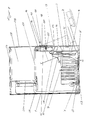
Figur 1 einen Querschnitt einer elektronischen Geräteanordnung,Figur 2 eine Vorderansicht der elektronischen Geräteanordnung nachFigur 1,Figur 3 eine perspektivische Ansicht des Gehäuses der elektronischen Geräteanordnung nachFigur 1.
- FIG. 1 shows a cross section of an electronic device arrangement,
- FIG. 2 shows a front view of the electronic device arrangement according to FIG. 1,
- FIG. 3 shows a perspective view of the housing of the electronic device arrangement according to FIG. 1.
Die in den Figuren dargestellte elektronische Geräteanordnung weist ein Gehäuse 1 auf, das aus elektrisch leitend miteinander verbundenen Blechteilen besteht, so daß eine dem erforderlichen Störschutz genugende Abschirmwirkung erreicht wird.The electronic device arrangement shown in the figures has a
Der untere Bereich des Gehäuses 1 besitzt eine stirnseitige Öffnung 2, die durch eine Verschlußtafel 3 verschließbar ist. Die Verschlußtafel 3 besteht aus einem Blech Z-förmigen Querschnitts.The lower area of the
Der untere Endschenkel 4 erstreckt sich im geschlossenen Zustand der Verschlußtafel um einen Abstand zurückspringend parallel zur vorderen Ebene des Gehäuses 1.In the closed state of the closure panel, the
An seinem unteren Ende ist der Endschenkel 4 am Gehäuse 1 angelenkt und um eine Schwenkachse S aus der mit durchgezogener Linie dargestellten Schließstellung in die mit unterbrochener Linie dargestellte Öffnungsstellung schwenkbar.At its lower end, the
Mit der Verschlußtafel 3 ist ein Leiterplattenhalter 6 fest verbunden, auf dem eine in Schließstellung sich etwa parallel zur Bodenfläche des Gehäuses 1 sich erstreckende erste Leiterplatte 7 befestigt ist, auf der aktive elektronische Bauteile 8 angeordnet sind und auf der senkrecht weitere Leiterplatten 9 elektrisch verbindend aufgesteckt sind. Diese weiteren Leiterplatten sind in Führungen des Leiterplattenhalters 6 gehalten und können mit elektronischen Bauteilen versehen sein.With the
Durch das Verschwenken der Verschlußtafel 3 wird gleichzeitig auch der Leiterplattenhalter 6 mit den Leiterplatten 7 und 9 verschwenkt, so daß diese in Öffnungsstellung sich zumindest weitgehend außerhalb des Gehäuses 1 befinden und so leicht ausgewechselt oder ergänzt werden können.By pivoting the
An dem Leiterplattenhalter 6 und dem unteren Endschenkel 4 der Verschlußtafel 3 sind Steckanschlüsse 10 zum Gehäuseäußeren gerichtet angeordnet, die über Leitungen bzw. Leiterbahnen mit der ersten Leiterplatte 7 verbunden sind und deren Kontaktöffnung durch eine entsprechende Öffnung im unteren Endschenkel 4 ragt. Wie an einem dargestellten Steckanschluß 10 zu sehen ist, ist auf diesen von außen ein Steckgegenstück 11 auf steckbar, das mit einem seitlichen Abgang einer Leitung 12 versehen ist.On the
Der obere Endschenkel 13 der Verschlußtafel 3 erstreckt sich in der schließstellung etwa in der Ebene des Gehäuses 1 und ist an seinem freien Ende mit einer Schraube 14 am Gehäuse 1 anschraubbar.In the closed position, the
Im Bereich des oberen Endschenkels 13 sind an der Innenseite Lüftereinheiten 15 befestigt, die Ober Ausnehmungen 16 in der Verschlußtafel 3 und außenseitig angeordnete Filtereinheiten 17 Luft von außen ansaugen und das Gehäuse zum Kühlen der elektronischen Bauteile durchblasen.In the area of the
Die Filtereinheiten 17 bestehen aus einem schalenförmigen Filtergrill 18, in dessen Schale eine Filtermatte 19 derart einlegbar ist, daß sie die Ausnehmung 16 überdeckt.The
An dem Filtergrill 18 sind Gewindebohrungen 20 ausgebildet, in die durch entsprechende Bohrungen in der Verschlußtafel 3 hindurchgeführte Rändeluchrauben 21 leicht von Rand eingeschraubt werden können, die die Filtereinheit 17 in ihrer Einbaulage halten.Threaded
Die von den Lüftereinheiten 15 in das Gehäuseinnere geblasene Luft strömt aus den in den Seitenwänden und der Rückwand des Gehäuses ausgebildeten Lüfterschlitzen 22 und aus den mit einem Lochblech versehenen Boden 23 und Deckel 24 des Gehäuses wieder nach draussen. Der dabei an den Wärme erzeugenden elektronischen Bauteilen vorbeiströmende Luftstrom kühlt diese.The air blown into the interior of the housing by the
Der die beiden Endschenkel 4 und 13 verbindende Verbindungssteg 25 bildet gleichzeitig eine Griffmulde 26, an der die Verschlußtafel 3 zum Verschwenken erfaßbar ist.The connecting
Über dem durch die Verschlußtafel 3 verschließbaren Bereich besitzt das Gehäuse 1 einen weiteren mit Einschubführungen 27 versehenen Bereich, der über der Öffnung 2 nach außen mündende Einschuböffnungen 28 besitzt.Above the area that can be closed by the
In diese Einschuböffnungen 28 sind mit Führungsgegenstocken versehene elektronische Geräte 29 derart einschiebbar, daß sie mit ihrer Frontseite im eingeschobenen Zustand die Einschuböffnungen 28 verschließen.
Im Bereich der Rückwand der Einschuböffnungen 28 sind Steckkontakte 30 angeordnet, in die entsprechende Steckgegenstücke an der Rückseite der elektronischen Geräte 29 kontaktierend einführbar sind.In the area of the rear wall of the
Die steckkontakte 30 sind über Leitungen 31 mit der ersten Leiterplatte 7 verbunden.The
Dadurch, daß durch die Lüftereinheiten 15 von den Filtereinheiten 17 gereinigte Luft in das Gehäuse 1 eingeblasen wird, entsteht im Gehäuse 1 ein gegenüber dem Gehäuseäußeren etwas erhöhter Druck. Dadurch können keine Verunreinigungen durch Öffnungen und Spalten in das Gehäuse 1 eindringen und zu Beschädigungen elektronischer Bauteile führen.Characterized in that air cleaned by the
Claims (22)
Applications Claiming Priority (2)
| Application Number | Priority Date | Filing Date | Title |
|---|---|---|---|
| DE3933319 | 1989-10-06 | ||
| DE3933319A DE3933319A1 (en) | 1989-10-06 | 1989-10-06 | ELECTRONIC DEVICE ARRANGEMENT |
Publications (2)
| Publication Number | Publication Date |
|---|---|
| EP0421096A2 true EP0421096A2 (en) | 1991-04-10 |
| EP0421096A3 EP0421096A3 (en) | 1992-06-24 |
Family
ID=6390906
Family Applications (1)
| Application Number | Title | Priority Date | Filing Date |
|---|---|---|---|
| EP19900115492 Withdrawn EP0421096A3 (en) | 1989-10-06 | 1990-08-13 | Electronic apparatus arrangement |
Country Status (5)
| Country | Link |
|---|---|
| US (1) | US5097386A (en) |
| EP (1) | EP0421096A3 (en) |
| JP (1) | JPH06103798B2 (en) |
| CA (1) | CA2027082A1 (en) |
| DE (1) | DE3933319A1 (en) |
Families Citing this family (13)
| Publication number | Priority date | Publication date | Assignee | Title |
|---|---|---|---|---|
| AT399630B (en) * | 1991-06-13 | 1995-06-26 | Elin Energieversorgung | HOUSING FOR INSERTS OF ELECTRONIC ASSEMBLIES |
| DE4121390C2 (en) * | 1991-06-28 | 1994-10-20 | Bosch Gmbh Robert | Method for producing a self-supporting thick-film structure |
| US5229925A (en) * | 1991-07-19 | 1993-07-20 | Valcom, Inc. | Modular front panel and enclosure for electronic apparatus |
| US5282114A (en) * | 1991-11-05 | 1994-01-25 | Codar Technology Inc. | Ruggedized computer assembly providing accessibility and adaptability to, and effective cooling of, electronic components |
| DE4209887C1 (en) * | 1992-03-26 | 1993-05-27 | Bicc-Vero Electronics Gmbh, 2800 Bremen, De | Drawer for holding electric components and circuit boards - |
| US5666264A (en) * | 1996-05-13 | 1997-09-09 | Nematron Corporation | Industrial computer workstation |
| TW315077U (en) * | 1997-01-29 | 1997-09-01 | Hon Hai Prec Ind Co Ltd | Computer housing |
| DE19707901A1 (en) * | 1997-02-27 | 1998-09-03 | Peter Leininger | Computer dust filter |
| JP3098980B2 (en) * | 1997-07-18 | 2000-10-16 | ファナック株式会社 | Housing structure of numerical controller |
| TW417800U (en) * | 1999-01-29 | 2001-01-01 | Hon Hai Prec Ind Co Ltd | Carrying frame of computer mother board |
| US6922336B2 (en) * | 2003-04-11 | 2005-07-26 | Hewlett-Packard Development Company, L.P. | Pivoted field replaceable unit apparatus and method |
| KR101239562B1 (en) * | 2008-07-25 | 2013-03-05 | 후지쯔 가부시끼가이샤 | Electronic device |
| GB2558576B (en) * | 2017-01-06 | 2020-06-24 | Dyson Technology Ltd | Hand held appliance |
Citations (4)
| Publication number | Priority date | Publication date | Assignee | Title |
|---|---|---|---|---|
| US2572617A (en) * | 1950-02-11 | 1951-10-23 | Bell Telephone Labor Inc | Maintenance bracket |
| GB755713A (en) * | 1954-12-06 | 1956-08-22 | Telephone Mfg Co Ltd | Improvements in or relating to chassis assemblies for electrical apparatus |
| DE1462199A1 (en) * | 1965-05-24 | 1969-03-27 | Siemens Ag | Frame for electrical telecommunications equipment |
| US3683238A (en) * | 1971-02-11 | 1972-08-08 | Westinghouse Electric Corp | Pivotally supported rack construction |
Family Cites Families (4)
| Publication number | Priority date | Publication date | Assignee | Title |
|---|---|---|---|---|
| US3188524A (en) * | 1962-09-20 | 1965-06-08 | Lockheed Aircraft Corp | High density circuit card packaging |
| US4268100A (en) * | 1979-01-05 | 1981-05-19 | International Business Machines Corporation | Pivotally mounted printed circuit board holder |
| US4523254A (en) * | 1983-12-28 | 1985-06-11 | Magnetic Peripherals Inc. | Equipment module |
| US4972296A (en) * | 1989-06-15 | 1990-11-20 | Northern Telecom Limited | Expandable modular switching unit |
-
1989
- 1989-10-06 DE DE3933319A patent/DE3933319A1/en not_active Withdrawn
-
1990
- 1990-08-13 EP EP19900115492 patent/EP0421096A3/en not_active Withdrawn
- 1990-10-05 JP JP2266583A patent/JPH06103798B2/en not_active Expired - Lifetime
- 1990-10-05 US US07/593,232 patent/US5097386A/en not_active Expired - Fee Related
- 1990-10-05 CA CA002027082A patent/CA2027082A1/en not_active Abandoned
Patent Citations (4)
| Publication number | Priority date | Publication date | Assignee | Title |
|---|---|---|---|---|
| US2572617A (en) * | 1950-02-11 | 1951-10-23 | Bell Telephone Labor Inc | Maintenance bracket |
| GB755713A (en) * | 1954-12-06 | 1956-08-22 | Telephone Mfg Co Ltd | Improvements in or relating to chassis assemblies for electrical apparatus |
| DE1462199A1 (en) * | 1965-05-24 | 1969-03-27 | Siemens Ag | Frame for electrical telecommunications equipment |
| US3683238A (en) * | 1971-02-11 | 1972-08-08 | Westinghouse Electric Corp | Pivotally supported rack construction |
Also Published As
| Publication number | Publication date |
|---|---|
| JPH06103798B2 (en) | 1994-12-14 |
| DE3933319A1 (en) | 1991-04-11 |
| EP0421096A3 (en) | 1992-06-24 |
| JPH03206688A (en) | 1991-09-10 |
| CA2027082A1 (en) | 1991-04-07 |
| US5097386A (en) | 1992-03-17 |
Similar Documents
| Publication | Publication Date | Title |
|---|---|---|
| DE19719507A1 (en) | Rack with subrack and ventilation device | |
| EP0421096A2 (en) | Electronic apparatus arrangement | |
| WO2004062329A1 (en) | Modules for a measuring device and measuring device | |
| DE102018008520A1 (en) | Display Equipped Controller | |
| DE3409022C2 (en) | ||
| EP0618758B1 (en) | Programmable control unit | |
| DE19500436C2 (en) | Electrical connector device | |
| DE3144131C2 (en) | ||
| WO1989004559A1 (en) | Electronic housing for severe environmental conditions | |
| DE102017214779A1 (en) | Electric control unit | |
| DE10326388A1 (en) | Measuring device modules and measuring device | |
| DE3524035C2 (en) | ||
| EP0584658A2 (en) | Distributor for EMI shielded cabinets | |
| DE2738399C3 (en) | Construction of a system for electrical information processing, in particular a telecontrol system | |
| DE2755761C2 (en) | Housings for electrical communications technology | |
| EP0669795A1 (en) | Enclosure for housing boards with components | |
| EP0934591B1 (en) | Sub-assembly for an assembly system | |
| EP0688157A2 (en) | Casing for electronic plug-in units | |
| DE3913923A1 (en) | MOUNTING DEVICE FOR ASSEMBLY UNITS | |
| DE3412593A1 (en) | Encapsulated assembly for electronic units | |
| DE2707975C3 (en) | Functional unit formed from electrical assemblies and a chassis | |
| DE19912030B4 (en) | air conditioning unit | |
| DE2827280C2 (en) | Device for connecting lines to electronic assemblies that can be pushed into subracks | |
| AT409047B (en) | DEVICE FOR GROUNDING A MODULAR HOUSING UNIT | |
| DE3643486A1 (en) | Mounting rack having a frame-like housing |
Legal Events
| Date | Code | Title | Description |
|---|---|---|---|
| PUAI | Public reference made under article 153(3) epc to a published international application that has entered the european phase |
Free format text: ORIGINAL CODE: 0009012 |
|
| AK | Designated contracting states |
Kind code of ref document: A2 Designated state(s): AT BE CH DE ES FR GB IT LI NL SE |
|
| PUAL | Search report despatched |
Free format text: ORIGINAL CODE: 0009013 |
|
| AK | Designated contracting states |
Kind code of ref document: A3 Designated state(s): AT BE CH DE ES FR GB IT LI NL SE |
|
| STAA | Information on the status of an ep patent application or granted ep patent |
Free format text: STATUS: THE APPLICATION IS DEEMED TO BE WITHDRAWN |
|
| 18D | Application deemed to be withdrawn |
Effective date: 19921229 |