EP0421063A2 - Process for amelioration of the adaptive stochastic precision of dosing of a controlled balance for differential dosing - Google Patents
Process for amelioration of the adaptive stochastic precision of dosing of a controlled balance for differential dosing Download PDFInfo
- Publication number
- EP0421063A2 EP0421063A2 EP90113498A EP90113498A EP0421063A2 EP 0421063 A2 EP0421063 A2 EP 0421063A2 EP 90113498 A EP90113498 A EP 90113498A EP 90113498 A EP90113498 A EP 90113498A EP 0421063 A2 EP0421063 A2 EP 0421063A2
- Authority
- EP
- European Patent Office
- Prior art keywords
- spectrum
- model
- disturbances
- power density
- circuit
- Prior art date
- Legal status (The legal status is an assumption and is not a legal conclusion. Google has not performed a legal analysis and makes no representation as to the accuracy of the status listed.)
- Granted
Links
Images

Classifications
-
- G—PHYSICS
- G01—MEASURING; TESTING
- G01G—WEIGHING
- G01G13/00—Weighing apparatus with automatic feed or discharge for weighing-out batches of material
- G01G13/24—Weighing mechanism control arrangements for automatic feed or discharge
- G01G13/248—Continuous control of flow of material
-
- G—PHYSICS
- G01—MEASURING; TESTING
- G01G—WEIGHING
- G01G11/00—Apparatus for weighing a continuous stream of material during flow; Conveyor belt weighers
- G01G11/08—Apparatus for weighing a continuous stream of material during flow; Conveyor belt weighers having means for controlling the rate of feed or discharge
- G01G11/086—Apparatus for weighing a continuous stream of material during flow; Conveyor belt weighers having means for controlling the rate of feed or discharge of the loss-in-weight feeding type
-
- B—PERFORMING OPERATIONS; TRANSPORTING
- B29—WORKING OF PLASTICS; WORKING OF SUBSTANCES IN A PLASTIC STATE IN GENERAL
- B29B—PREPARATION OR PRETREATMENT OF THE MATERIAL TO BE SHAPED; MAKING GRANULES OR PREFORMS; RECOVERY OF PLASTICS OR OTHER CONSTITUENTS OF WASTE MATERIAL CONTAINING PLASTICS
- B29B7/00—Mixing; Kneading
- B29B7/02—Mixing; Kneading non-continuous, with mechanical mixing or kneading devices, i.e. batch type
- B29B7/22—Component parts, details or accessories; Auxiliary operations
- B29B7/24—Component parts, details or accessories; Auxiliary operations for feeding
- B29B7/242—Component parts, details or accessories; Auxiliary operations for feeding in measured doses
-
- B—PERFORMING OPERATIONS; TRANSPORTING
- B29—WORKING OF PLASTICS; WORKING OF SUBSTANCES IN A PLASTIC STATE IN GENERAL
- B29B—PREPARATION OR PRETREATMENT OF THE MATERIAL TO BE SHAPED; MAKING GRANULES OR PREFORMS; RECOVERY OF PLASTICS OR OTHER CONSTITUENTS OF WASTE MATERIAL CONTAINING PLASTICS
- B29B7/00—Mixing; Kneading
- B29B7/30—Mixing; Kneading continuous, with mechanical mixing or kneading devices
- B29B7/58—Component parts, details or accessories; Auxiliary operations
- B29B7/60—Component parts, details or accessories; Auxiliary operations for feeding, e.g. end guides for the incoming material
- B29B7/603—Component parts, details or accessories; Auxiliary operations for feeding, e.g. end guides for the incoming material in measured doses, e.g. proportioning of several materials
Definitions
- the invention relates to a method for improving the dosing accuracy of a regulated differential dosing scale according to the preamble of patent claim 1 and a device for carrying out the method according to the preamble of patent claim 4.
- the delivery rate is generally determined from the weight of the conveyor system that changes over time.
- the weight is sampled at certain time intervals and a signal is formed from this by a differentiation, which is proportional to the delivery rate, which varies due to fluctuations in bulk density.
- This weight signal also contains components that are caused by transducer malfunctions.
- sensor disorders can e.g. B. caused by acceleration processes at the measurement site, by electrical noise or quantization noise.
- the fluctuations in bulk density represent disturbances which, for. B. may have arisen due to different lumpy bulk materials or non-uniformly supplied material. Since such disturbances are unpredictable in time, they are generally referred to as stochastic disturbances.
- Sensor disorders are usually not identified by a weight sensor system and therefore falsify the dosing result.
- a regulated differential metering scale is known in which the transducer malfunctions and bulk density fluctuations are recorded by means of a model calculation and the size of which is taken into account when forming an estimated value.
- a Kalman filter process is used to generate filtered estimates of the actual weight and the Flow rate of the material applied.
- the estimated flow rate signal is generated on the basis of the measured weight and a stochastic model for a specific noise process that influences the system.
- the models for the different types of noise are modified according to the size of their influence and the probability of their occurrence.
- the transducer disturbances are taken into account in that the variance ⁇ 2 n , which is used to calculate the model, must be determined experimentally or empirically before the special dosing system is put into operation.
- the mathematical model can only be calculated with the aid of the previously experimentally or empirically determined parameter of the special regulated differential metering scale.
- the invention is therefore based on the object of creating a method and a device of the type mentioned at the outset in which the parameters of stochastic disturbances of a special pickup system can be determined automatically.
- the invention has the advantage that certain characteristic values of the stoachastic disturbances which result from the sensor disturbances of a differential metering scale can basically be derived from the measured values. It is therefore not necessary to recapture the relevant parameters when device parts of the transducer system are replaced or repaired. Furthermore, it is not necessary to check the corresponding device parameters at certain time intervals. It is therefore not necessary to switch off the control circuit to record these parameters.
- the invention also has the advantage that the setting cycle is not coupled to the timing of the control. This allows the control to be better matched to the respective dosing system. In this way, it is possible to increase the cycle time for setting the controller in certain dosing systems that operate largely under unchanged environmental conditions, while the control cycle time can be selected to be very short.
- the invention has the advantage that the monochromatic disturbances can be recognized and therefore can be separated from the stochastic disturbance components. As a result, a considerable improvement in the dosing accuracy can be achieved.
- the short cycle time of the controller setting offers the advantage over a higher cycle time of the control processes that the computational effort for determining the proportion of the fault can be kept comparatively low.
- a regulated differential metering scale which essentially consists of a metering system 10, a weighing device 4, an estimator 12, an evaluation device 14 and a controller 5.
- the dosing system 10 contains a storage container 1 which is filled with a bulk material 2.
- the bulk material to be metered passes from the storage container 1 to a discharge element which is designed as a screw conveyor 11.
- the screw conveyor 11 is connected to a drive motor 3, the speed of which determines the discharge quantity of the bulk material.
- This dosing system 10, consisting of the storage container 1 with bulk material, the discharge member 11 and the drive motor 3, is arranged on a weighing device 4, which essentially consists of a weighing cell.
- the load cell delivers an electrical signal that corresponds to the weight of the metering system 10 and represents a weight signal.
- the weighing device 4 is connected to an estimator 12, which samples the weight signal at certain time intervals and, by differentiation, forms an estimated value signal therefrom which corresponds to the delivery rate of the discharge member 11.
- the estimator 12 is designed as a differentiating circuit, the output of which is connected to an addition point 13.
- the estimate signal generated by the estimator 12 represents an actual value signal.
- the addition point 13 is also supplied with a setpoint signal W (t), which is not shown in any more detail and which contains a measure of the desired delivery rate. If the actual value signal deviates from the nominal value signal, the addition point 13 forms a control deviation signal which is fed to the controller 5.
- the controller 5 forms an actuating signal therefrom, which controls the drive motor 3 in accordance with the detected control deviation.
- the estimator 12, the controller 5, the addition point 13 and the servomotor 3 represent the control device.
- the estimated value signal generated by the estimator 12 also contains interference components which are based on the bulk density of the volume flow that changes over time. Furthermore go through the type of mass determination z. B. also forces in the weight signal, which are caused by acceleration processes at the installation site. However, noise disturbances also act on the transducer system Cause measurement inaccuracy. These disturbances acting on the sensor system can be referred to as sensor disturbances. In order to minimize the influence of such disturbances on the controlled system, the estimate signal is fed to an evaluation device 14 which determines the proportion of such disturbances and generates a signal therefrom which adapts the transfer function of the controller 5 in accordance with the respective disturbance components.
- the evaluation device 14 contains an analyzer circuit 15, which samples the estimated value for a specific period of time.
- a sampling period of approximately 100 seconds has proven to be expedient. In order to achieve sufficient accuracy, the sampling period is in any case chosen to be longer than the control cycle.
- a discrete Fourie transformation is carried out in the analyzer circuit from the sampled estimated value signal, which calculates the power density spectrum ⁇ 1 (f) of the sampled estimated value signal.
- this frequency spectrum contains strong power components in narrow frequency ranges. These frequency ranges with a high power density are based on monochromatic interference, the spectrum of which must therefore be separated from the spectrum of the stochastic interference. Since the position of the monomchromatic interference is generally known, the spectrum ⁇ 1 is fed to an identification circuit 6, which uses it to determine the frequency ranges which exceed a certain power density and are therefore fixed as frequency ranges of the monochromatic interference.
- a correction circuit 16 which attenuates the power density in these frequency ranges so that they correspond to the value of the power density of the stochastic disturbances.
- Such a correction circuit 16 can also be designed such that only the spectrum between the frequency ranges with high power density is used to evaluate the stochastic interference.
- a power density spectrum is therefore obtained which contains only the parts of the spectrum of the stochastic disturbances ⁇ 2 25.
- This is now fed to a comparator circuit 17, which compares the spectrum ⁇ 2 25 with model spectra 20, 26 generated by a model computer 7.
- the model computer 7 calculates a number of different model spectra which reflect the mathematical structure of the physical properties of the stochastic disturbances.
- the model computer 7 calculates these model spectra with the aid of predetermined dependencies which are known.
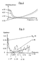
- Fig. 2 of the drawings Such a model spectrum of the Stoachic disturbances of the sensor system and of the bulk density fluctuations is shown in Fig. 2 of the drawings.
- the power density spectrum b 23 which corresponds to the transducer interference, increases proportionally with the square of the frequency f.
- the drawing also contains the characteristic curves c 22 and d 21, which each represent different proportions of the bulk density fluctuations.
- the drawing shows from the characteristic curve d 21 the proportion of the spectrum of the power density of the bulk density density fluctuations, which is proportional to the function runs.
- T ⁇ represents a time constant and f the frequency of the power density of the disturbances of the bulk density fluctuations.
- the characteristic curve c 22 the characteristic spectra, a constant proportion of the bulk density density fluctuations is shown.
- the entire power density spectrum of a model of the stochastic disturbances can be seen from the characteristic curve a 20, which represents the sum of the individual power density spectra. From this functional combination slope, the model computer 7 calculates an abundance of model spectra, which are queried by the comparator circuit 17 and compared with the spectrum ⁇ 2 25 derived from the estimated value signal.
- the best approximation in terms of the smallest error squares of the power density spectrum ⁇ 2 25 formed by the correction circuit 17 is determined by the model spectrum ⁇ M 26.
- Such a power density spectrum ⁇ 2 25 and the model spectra a 26, b 29, c 27 and d 28 which can be determined therefrom can be seen from FIG. 3 of the drawing.
- the characteristic curve c 27 represents the spectrum of the proportion of the constant bulk density fluctuations
- the characteristic curve d 28 represents the spectrum of the proportion of the bulk density density fluctuations, which is proportional runs.
- the characteristic curve b 29 shows the model spectrum derived from the power density spectrum ⁇ 2 25, which corresponds to the sensor disturbances. The sum of the individual model spectra of the characteristic curves b 29, c 27 and d 28 thus results in the model spectrum ⁇ M 26 which comes closest to the power density spectrum ⁇ 2 25 and is shown in the course of the characteristic curve a 26.
- the model parameter ⁇ nn represents a constant power density of a noise spectrum, which is caused by the transducer interference.
- the spectra ⁇ ⁇ 1 and ⁇ ⁇ 2 correspond to constant power density spectra, which can be derived from the proportions of the bulk density density fluctuations .
- T ⁇ represents a time constant.
- the controller setting circuit 18 calculates the optimal transfer function H K (s) of the control loop in terms of the smallest mean error squares from the mathematical structure and the model parameters ⁇ nn , ⁇ ⁇ 1 , ⁇ ⁇ 2 and T ⁇ .
- A+ (s) indicates the poles and zeros of the function in the left s-half plane of the complex number system.
- the complex number plane is represented so that the real part is determined by the abscissa and the imaginary part by the ordinate.
- a ⁇ (s) contains the poles and poles and zeros of the function in the right complex s-half plane.
- B+ (s) contains the shares with the poles in the left s-half-plane and B ⁇ (s) the shares with poles in the right s-half-plane.
- the controller setting circuit 18 forms from the components A+ and B+ calculated by the controller setting circuit 18 in accordance with the equation the optimal transfer function of the control loop. Through a further calculation step, the controller setting circuit 18 determines according to a method according to the equation the optimal transfer function of the controller 5 and forms a signal that serves to set the controller 5.
- Such a controller setting process is expediently carried out for a detection period of approximately 100 seconds.
- Such an acquisition period is expediently chosen because the accuracy of the optimization process increases with the duration of the acquired measurement signal.
- a new setting process is usually only repeated after a period of approx. 10 seconds. This period represents an empirical value that is largely determined by the expected change in stochastic disorders. It is therefore also conceivable to repeat the setting process only after much longer periods.
- Such a method for improving the dosing accuracy of differential dosing scales can also be used with other weighing systems.
- this method can be used in general for control methods that have both stochastic and monochromatic components.
Abstract
Description
Die Erfindung betrifft ein Verfahren zur Verbesserung der Dosiergenauigkeit einer geregelten Differentialdosierwaage gemäß dem Oberbegriff des Patentanspruchs 1 und eine Vorrichtung zur Durchführung des Verfahrens gemäß dem Oberbegriff des Patentanspruchs 4.The invention relates to a method for improving the dosing accuracy of a regulated differential dosing scale according to the preamble of
Bei geregelten Differentialdosierwaagen wird die Förderstärke in der Regel aus dem zeitlich veränderten Gewicht des Fördersystems ermittelt. Dabei wird das Gewicht in bestimmten Zeitabständen abgetastet und hieraus durch eine Differentation ein Signal gebildet, das der Förderstärke proportional ist, die aufgrund von Schüttgutdichteschwankungen variiert. In diesem Gewichtssignal sind auch Anteile enthalten, die von Aufnehmerstörungen verursacht sind. Derartige Aufnehmerstörungen können z. B. durch Beschleungigungsvorgänge am Meßort, durch elektrisches Rauschen oder Quantisierungsrauschen hervorgerufen sein. Hingegen stellen die Schüttgutdichteschwankungen Störungen dar, die z. B. aufgrund von unterschiedlich klumpigen Schüttgütern oder ungleichförmig zugeführten Materials entstanden sein können. Da derartige Störungen zeitlich unvorhersehbar sind, bezeichnet man sie allgemein auch als stochastische Störungen. Aufnehmerstörungen werden üblicherweise von einem Gewichtsaufnehmersystem nicht identifiziert und verfälschen daher das Dosierergebnis.In the case of regulated differential dosing scales, the delivery rate is generally determined from the weight of the conveyor system that changes over time. The weight is sampled at certain time intervals and a signal is formed from this by a differentiation, which is proportional to the delivery rate, which varies due to fluctuations in bulk density. This weight signal also contains components that are caused by transducer malfunctions. Such sensor disorders can e.g. B. caused by acceleration processes at the measurement site, by electrical noise or quantization noise. On the other hand, the fluctuations in bulk density represent disturbances which, for. B. may have arisen due to different lumpy bulk materials or non-uniformly supplied material. Since such disturbances are unpredictable in time, they are generally referred to as stochastic disturbances. Sensor disorders are usually not identified by a weight sensor system and therefore falsify the dosing result.
Aus der DE-OS 37 21 186 ist eine geregelte Differentialdosierwaage bekannt, bei der die Aufnehmerstörungen und Schüttgutdichteschwankungen durch eine Modellrechnung erfaßt und deren Größe bei der Bildung eines Schätzwertes mit berücksichtigt wird. Bei dem dort beschriebenen Verfahren wird ein Kalman-Filter-Prozeß zur Erzeugung gefilteter Schätzwerte des tatsächlichen Gewichts und der Durchflußrate des Materials angewandt. Das geschätzte Durchflußmengensignal wird dabei auf der Grundlage des gemessenen Gewichts und eines stochastischen Modells für einen bestimmten, das System beeinflussenden Rauschvorgang erzeugt. Die Modelle für die verschiedenen Rauscharten werden entsprechend der Größe ihres Einflusses und der Wahrscheinlichkeit ihres Auftretens modifiziert. Bei dem bekannten Verfahren werden die Aufnehmerstörungen dadurch berücksichtigt, daß vor Inbetriebnahme des speziellen Dosiersystems die Varianz σ²n, die zur Berechnung des Modells dient, experimentell oder empirisch ermittelt werden muß. Bei einem derartigen Verfahren ist es nachteilig, daß das mathematische Modell nur mit Hilfe der vorher experimentell oder empirisch ermittelten Kenngröße der speziellen geregelten Differentialdosierwaage berechnet werden kann.From DE-OS 37 21 186 a regulated differential metering scale is known in which the transducer malfunctions and bulk density fluctuations are recorded by means of a model calculation and the size of which is taken into account when forming an estimated value. In the method described there, a Kalman filter process is used to generate filtered estimates of the actual weight and the Flow rate of the material applied. The estimated flow rate signal is generated on the basis of the measured weight and a stochastic model for a specific noise process that influences the system. The models for the different types of noise are modified according to the size of their influence and the probability of their occurrence. In the known method, the transducer disturbances are taken into account in that the variance σ² n , which is used to calculate the model, must be determined experimentally or empirically before the special dosing system is put into operation. With such a method, it is disadvantageous that the mathematical model can only be calculated with the aid of the previously experimentally or empirically determined parameter of the special regulated differential metering scale.
Der Erfindung liegt deshalb die Aufgabe zugrunde, ein Verfahren und eine Einrichtung der eingangs genannten Art zu schaffen, bei dem die Kenngrößen stochastischer Störungen eines spezielles Aufnehmersystems selbsttätig ermittelbar sind.The invention is therefore based on the object of creating a method and a device of the type mentioned at the outset in which the parameters of stochastic disturbances of a special pickup system can be determined automatically.
Diese Aufgabe wird durch die im Patentanspruch 1 und 5 angegebene Erfindung gelöst. Weiterbildungen und vorteilhafte Ausführungsbeispiele sind in den Unteransprüchen angegeben.This object is achieved by the invention specified in
Die Erfindung hat den Vorteil, daß bestimmte Kennwerte der stoachastischen Störungen, die aus den Aufnehmerstörungen einer Differentialdosierwaage herrühren, im Grunde aus den Meßwerten ableitbar sind. So ist es deshalb auch nicht erforderlich, die entsprechenden Kennwerte wieder neu zu erfassen, wenn Geräteteile des Aufnehmersystems ausgetauscht oder instandgesetzt werden. Weiterhin ist es auch nicht erforderlich, die entsprechenden Gerätekennwerte in gewissen Zeitabständen wieder zu überprüfen. Eine Abschaltung des Regelkreises zur Aufnahme dieser Kennwerte ist deshalb entbehrlich.The invention has the advantage that certain characteristic values of the stoachastic disturbances which result from the sensor disturbances of a differential metering scale can basically be derived from the measured values. It is therefore not necessary to recapture the relevant parameters when device parts of the transducer system are replaced or repaired. Furthermore, it is not necessary to check the corresponding device parameters at certain time intervals. It is therefore not necessary to switch off the control circuit to record these parameters.
Die Erfindung hat darüber hinaus noch den Vorteil, daß der Einstelltakt nicht an den Zeittakt der Regelung gekoppelt ist. Dadurch kann die Regelung besser auf das jeweilige Dosiersystem abgestimmt werden. So ist es möglich, bei bestimmten Dosiersystemen, die weitgehend bei unveränderten Umweltbedingungen arbeiten, die Taktzeit zur Reglereinstellung zu erhöhen, während die Regeltaktzeit sehr klein gewählt werden kann.The invention also has the advantage that the setting cycle is not coupled to the timing of the control. This allows the control to be better matched to the respective dosing system. In this way, it is possible to increase the cycle time for setting the controller in certain dosing systems that operate largely under unchanged environmental conditions, while the control cycle time can be selected to be very short.
Weiterhin besitzt die Erfindung noch den Vorteil, daß die monochromatischen Störungen erkennbar und deshalb von den stochastischen Störungsanteilen getrennt werden können. Dadurch ist eine beträchtliche Verbesserung der Dosiergenauigkeit erreichbar.Furthermore, the invention has the advantage that the monochromatic disturbances can be recognized and therefore can be separated from the stochastic disturbance components. As a result, a considerable improvement in the dosing accuracy can be achieved.
Im übrigen bietet die geringe Taktzeit der Reglereinstellung gegenüber einer höheren Taktzeit der Regelungsvorgänge den Vorteil, daß der Rechenaufwand zur Ermittlung des Störungsanteils vergleichsweise gering gehalten werden kann.In addition, the short cycle time of the controller setting offers the advantage over a higher cycle time of the control processes that the computational effort for determining the proportion of the fault can be kept comparatively low.
Die Erfindung wird anhand eines Ausführungsbeispiels, das in der Zeichnung dargestellt ist, näher beschrieben. Es zeigen:
- Fig. 1: die schematische Darstellung einer geregelten Differentialdosierwaage;
- Fig. 2: den Kennlinienverlauf charakteristischer Spektren und
- Fig. 3: ein bestimmtes Spektrum der stochastischen Störungen und der daraus bestimmten Modellspektren.
- Fig. 1: the schematic representation of a regulated differential dosing scale;
- 2: the characteristic curve of characteristic spectra and
- 3: a certain spectrum of the stochastic disturbances and the model spectra determined therefrom.
In Fig. 1 der Zeichnung ist eine geregelte Differentialdosierwaage dargestellt, die im wesentlichen aus einem Dosiersystem 10, einer Wägevorrichtung 4, einem Schätzer 12, einer Auswerteeinrichtung 14 und einem Regler 5 besteht.1 of the drawing shows a regulated differential metering scale, which essentially consists of a
Das Dosiersystem 10 enthält einen Vorratsbehälter 1, der mit einem Schüttgut 2 gefüllt ist. Vom Vorratsbehälter 1 gelangt das zu dosierende Schüttgut auf ein Austragsorgan, das als Förderschnecke 11 ausgebildet ist. Die Förderschnecke 11 ist mit einem Antriebsmotor 3 verbunden, dessen Drehzahl die Austragsmenge des Schüttgutes bestimmt. Dieses aus dem Vorratsbehälter 1 mit Schüttgut, dem Austragsorgan 11 und dem Antriebsmotor 3 bestehende Dosiersystem 10 ist auf einer Wägevorrichtung 4 angeordnet, die im wesentlichen aus einer Wägezelle besteht. Die Wägezelle liefert dabei ein elektrisches Signal, das der Gewichtskraft des Dosiersystems 10 entspricht und ein Gewichtssignal darstellt. Die Wägevorrichtung 4 ist mit einem Schätzer 12 verbunden, der das Gewichtssignal in bestimmten Zeitabständen abtastet und durch Differentation daraus ein Schätzwertsignal bildet, das der Förderstärke des Austragsorgans 11 entspricht. Der Schätzer 12 ist als eine Differenzierschaltung ausgebildet, dessen Ausgang mit einer Additionsstelle 13 verbunden ist. Das vom Schätzer 12 erzeugte Schätzwertsignal stellt dabei ein Istwertsignal dar. Der Additionsstelle 13 wird noch ein nicht näher dargestelltes Sollwertsignal W(t) zugeführt, das ein Maß für die gewünschte Förderstärke enthält. Soweit das Istwertsignal vom Sollwertsignal abweicht, bildet die Additionsstelle 13 ein Regelabweichungssignal, das dem Regler 5 zugeführt wird. Der Regler 5 bildet daraus ein Stellsignal, das den Antriebsmotor 3 entsprechend der festgestellten Regelabweichung steuert. Der Schätzer 12, der Regler 5, die Additionsstelle 13 und der Stellmotor 3 stellen die Regeleinrichtung dar.The
Das vom Schätzer 12 erzeugte Schätzwertsignal enthält auch Störanteile, die auf der zeitlich veränderten Schüttgutdichte des Volumenstroms beruhen. Weiterhin gehen durch die Art der Massenbestimmung z. B. auch Kräfte in das Gewichtssignal ein, die durch Beschleunigungsvorgänge am Aufstellungsort entstanden sind. Auf das Aufnehmersystem wirken aber auch noch Rauschstörungen, die auch eine Meßungenauigkeit bewirken. Diese auf das Aufnehmersystem wirkenden Störungen können als Aufnehmerstörungen bezeichnet werden. Um den Einfluß derartiger Störungen auf die Regelstrecke zu minimieren, wird das Schätzwertsignal einer Auswerteeinrichtung 14 zugeführt, die den Anteil derartiger Störungen ermittelt und daraus ein Signal erzeugt, das die Übertragungsfunktion des Reglers 5 entsprechend der jeweiligen Störanteile anpaßt.The estimated value signal generated by the
Die Auswerteeinrichtung 14 enthält eine Analysatorschaltung 15, die den Schätzwert für einen bestimmten Zeitraum abtastet. Dabei hat sich ein Abtastzeitraum von ca. 100 Sekunden als zweckmäßig erwiesen. Zur Erzielung einer hinreichenden Genauigkeit wird der Abtastzeitraum in jedem Fall größer gewählt, als der Regelzyklus.The
Aus dem abgetasteten Schätzwertsignal wird in der Analysatorschaltung eine diskrete Fourietransformation durchgeführt, die das Leistungsdichtespektrum φ1(f) des abgetasteten Schätzwertsignals berechnet. Dieses Frequenzspektrum enthält bei realen Dosierwaageanlagen, insbesondere bei solchen mit umlaufenden Teilen, starke Leistungsanteile in engen Frequenzbereichen. Diese Frequenzbereiche mit starker Leistungsdichte beruhen auf monochromatischen Störungen, deren Spektrum deshalb von dem Spektrum der stochastischen Störungen zu trennen ist. Da die Lage der monomchromatischen Störungen im allgemeinen bekannt ist, wird das Spektrum φ1 einer Identifizierungsschaltung 6 zugeführt, die daraus die Frequenzbereiche bestimmt, die eine bestimmte Leistungsdichte überschreiten und somit als Frequenzbereiche der monochromatischen Störungen festliegen.A discrete Fourie transformation is carried out in the analyzer circuit from the sampled estimated value signal, which calculates the power density spectrum φ1 (f) of the sampled estimated value signal. In real dosing weigher systems, especially those with rotating parts, this frequency spectrum contains strong power components in narrow frequency ranges. These frequency ranges with a high power density are based on monochromatic interference, the spectrum of which must therefore be separated from the spectrum of the stochastic interference. Since the position of the monomchromatic interference is generally known, the spectrum φ1 is fed to an
Diese festgestellten Frequenzbereiche mit hoher Leistungsdichte werden einer Korrekturschaltung 16 zugeführt, die die Leistungsdichte in diesen Frequenzbereichen abschwächt, so daß diese dem Wert der Leistungsdichte der stochastischen Störungen entsprechen. Eine derartige Korrekturschaltung 16 kann aber auch so ausgebildet sein, daß nur das Spektrum zwischen den Frequenzbereichen mit hoher Leistungsdichte zur Auswertung der stochastischen Störungen verwandt wird.These determined frequency ranges with high power density are fed to a
Am Ausgang der Korrekturschaltung 16 erhält man daher ein Leistungsdichtespektrum, das nur die Anteile des Spektrums der stochastischen Störungen φ2 25 enthält. Dieses wird nun einer Vergleicherschaltung 17 zugeführt, die das Spektrum φ2 25 mit von einem Modellrechner 7 erzeugten Modellspektren 20, 26 vergleicht. Dabei errechnet der Modellrechner 7 eine Reihe unterschiedlicher Modellspektren, die die mathematische Struktur der physikalischen Eigenschaften der stochastischen Störungen wiedergeben. Diese Modellspektren errechnet der Modellrechner 7 mit Hilfe vorgegebener Abhängigkeiten, die bekannt sind.At the output of the
Ein derartiges Modellspektrum der stoachstischen Störungen des Aufnehmersystems und der Schüttgutdichteschwankungen ist in Fig. 2 der Zeichnungen dargestellt. Aus der Zeichnung ist zu entnehmen, daß das Leistungsdichtespektrum b 23, das den Aufnehmerstörungen entspricht, proportional mit dem Quadrat der Frequenz f ansteigt. Weiterhin enthält die Zeichnung die Kennlinien c 22 und d 21, die jeweils verschiedene Anteile der Schüttgewichtsschwankungen darstellen. Der Zeichnung ist aus der Kennlinie d 21 der Anteil des Spektrums der Leistungsdichte der Schüttgewichtsdichteschwankungen zu entnehmen, der proportional der Funktion
An diskreten Frequenzpunkten wird nun die im Sinne der kleinsten Fehlerquadrate beste Näherung des durch die Korrekturschaltung 17 gebildeten Leistungsdichtespektrums φ2 25 durch das Modellspektrum φM 26 ermittelt. Ein derartiges Leistungsdichtespektrum φ2 25 und den daraus ermittelbaren Modellspektren a 26, b 29, c 27 und d 28 ist aus Fig. 3 der Zeichnung ersichtlich. Dabei stellt die Kennlinie c 27 das Spektrum des Anteils der konstanten Schüttgewichtsschwankungen dar, während die Kennlinie d 28 das Spektrum des Anteils der Schüttgewichtsdichteschwankungen wiedergibt, das proportional
Durch die Feststellung des entsprechenden Modellspektrums φM 26 anhand des Leistungsdichtespektrums φ2 26 ergeben sich auch die entsprechenden Modellparameter φnn, φρρ1, φρρ2 und Tρ. Dabei stellt der Modellparameter φnn eine konstante Leistungsdichte eines Rauschspektrums dar, das von den Aufnehmerstörungen verursacht wird. Die Spektren φρρ1 und φρρ2 entsprechen konstanten Leistungsdichtespektren, die aus den Anteilen der Schüttgewichtsdichteschwankungen ableitbar sind. Hingegen stellt Tρ eine Zeitkonstante dar. Diese Modellparameter ergeben sich aus dem funtkionellen Zusammenhang der charakteristischen Spektren der Aufnehmerstörungen und der Schüttgutdichtestörungen, die Anhand der Beschreibung zu Fig. 2 der Zeichnung aufgezeigt sind.By determining the corresponding
Mathematisch ergibt sich daher folgendes Modell der stochastischen Störungen
Aus dem mathematischen Modell ergibt sich auch die Struktur des Modells, die der Modellrechner 7 einer Reglereinstellschaltung 18 zuführt. Die Reglereinstellschaltung 18 errechnet aus der mathematischen Struktur und den Modellparametern φnn, φρρ1, φρρ2 und Tρ die optimale Übertragungsfunktion HK(s) des Regelkreises im Sinne der kleinsten mittleren Fehlerquadrate. Dazu werden zunächst die Leistungsdichten nach der Methode der spektralen Faktorisierung entsprechend der folgenden Gleichungen zerlegt:
s²φnn(s) + φρρ (s) = A⁺(s)A⁻(s)
φρρ (s) = A⁻(s) (B₊(s) + B₋(s))The structure of the model, which the
s²φ nn (s) + φ ρρ (s) = A⁺ (s) A⁻ (s)
φ ρρ (s) = A⁻ (s) (B₊ (s) + B₋ (s))
Wobei A⁺(s) die Pole und Nullstellen der Funktion in der linken s-Halbebene des komplexen Zahlensystems angibt. Dabei wird die komplexe Zahlenebene so dargestellt, daß der Realteil durch die Abzisse und der Imaginärteil durch die Ordinate bestimmt ist. A⁻(s) enthält die Pole und Pole und Nullstellen der Funktion in der rechten komplexen s-Halbebene. B₊(s) enthält die Anteile mit den Polen in der linken s-Halbebene und B₋(s) die Anteile mit Polen in der rechten s-Halbebene. Dabei gibt der Buchstabe s die komplexe Frequenz bei der Laplace-Transformation an, die aus der Frequenz f aus der Gleichung s = C + j2πf ableitbar ist. In dieser Gleichung stellt C eine Konstante dar.Where A⁺ (s) indicates the poles and zeros of the function in the left s-half plane of the complex number system. The complex number plane is represented so that the real part is determined by the abscissa and the imaginary part by the ordinate. A⁻ (s) contains the poles and poles and zeros of the function in the right complex s-half plane. B₊ (s) contains the shares with the poles in the left s-half-plane and B₋ (s) the shares with poles in the right s-half-plane. The letter s indicates the complex frequency in the Laplace transformation, which can be derived from the frequency f from the equation s = C + j2πf. In this equation, C is a constant.
Aus den von der Reglereinstellschaltung 18 errechneten Anteilen A⁺ und B₊ bildet die Reglereinstellschaltung 18 entsprechend der Gleichung

Ein derartiger Reglereinstellvorgang wird zweckmäßigerweise für einen Erfassungszeitraum von ca. 100 Sekunden durchgeführt. Ein solcher Erfassungszeitraum wird zweckmäßigerweise deshalb gewählt, weil die Genauigkeit des Optimierungsvorgangs mit der Dauer des erfaßten Meßsignals ansteigt. Ein erneuter Einstellvorgang wird üblicherweise erst nach einem Zeitraum von ca. 10 Sekunden wiederholt. Dieser Zeitraum stellt einen Erfahrungswert dar, der weitgehend von der erwarteten Veränderung der stochastischen Störungen bestimmt wird. Es ist deshalb auch denkbar, den Einstellvorgang erst nach weitaus längeren Zeiträumen zu wiederholen.Such a controller setting process is expediently carried out for a detection period of approximately 100 seconds. Such an acquisition period is expediently chosen because the accuracy of the optimization process increases with the duration of the acquired measurement signal. A new setting process is usually only repeated after a period of approx. 10 seconds. This period represents an empirical value that is largely determined by the expected change in stochastic disorders. It is therefore also conceivable to repeat the setting process only after much longer periods.
Ein derartiges Verfahren zur Verbesserung der Dosiergenauigkeit von Differentialdosierwaagen ist auch bei anderen Wägesystemen anwendbar. Darüber hinaus ist dieses Verfahren ganz allgemein bei Regelungsverfahren einsetzbar, die sowohl Störungen mit stochastischen als auch mit monochromatischen Anteilen aufweisen.Such a method for improving the dosing accuracy of differential dosing scales can also be used with other weighing systems. In addition, this method can be used in general for control methods that have both stochastic and monochromatic components.
Claims (4)
Priority Applications (1)
| Application Number | Priority Date | Filing Date | Title |
|---|---|---|---|
| AT90113498T ATE103708T1 (en) | 1989-10-06 | 1990-07-14 | METHOD OF IMPROVING THE ADAPTIVE STOCHASTIC FEEDING ACCURACY OF A CONTROLLED LOSS-IN FEEDER. |
Applications Claiming Priority (2)
| Application Number | Priority Date | Filing Date | Title |
|---|---|---|---|
| DE3933471A DE3933471A1 (en) | 1989-10-06 | 1989-10-06 | METHOD AND DEVICE FOR IMPROVING THE DOSING ACCURACY OF A REGULATED DIFFERENTIAL DOSING SCALE |
| DE3933471 | 1989-10-06 |
Publications (3)
| Publication Number | Publication Date |
|---|---|
| EP0421063A2 true EP0421063A2 (en) | 1991-04-10 |
| EP0421063A3 EP0421063A3 (en) | 1991-07-17 |
| EP0421063B1 EP0421063B1 (en) | 1994-03-30 |
Family
ID=6390996
Family Applications (1)
| Application Number | Title | Priority Date | Filing Date |
|---|---|---|---|
| EP90113498A Expired - Lifetime EP0421063B1 (en) | 1989-10-06 | 1990-07-14 | Process for amelioration of the adaptive stochastic precision of dosing of a controlled balance for differential dosing |
Country Status (6)
| Country | Link |
|---|---|
| US (1) | US5132897A (en) |
| EP (1) | EP0421063B1 (en) |
| AT (1) | ATE103708T1 (en) |
| DE (2) | DE3933471A1 (en) |
| DK (1) | DK0421063T3 (en) |
| ES (1) | ES2051414T3 (en) |
Cited By (2)
| Publication number | Priority date | Publication date | Assignee | Title |
|---|---|---|---|---|
| EP0617262A1 (en) * | 1993-03-22 | 1994-09-28 | Carl Schenck Ag | Method for cancelling interference in a loss in weight feeder and device for carrying out the method |
| DE4331057C1 (en) * | 1993-09-13 | 1995-01-12 | Gericke Gmbh | Optimising the stirrer rotational speed in a mechanical metering device |
Families Citing this family (63)
| Publication number | Priority date | Publication date | Assignee | Title |
|---|---|---|---|---|
| US5260880A (en) * | 1987-08-04 | 1993-11-09 | Accurate, Inc. | Loss-in-weight feeder system |
| JPH04308901A (en) * | 1991-04-05 | 1992-10-30 | Nec Corp | State estimating device |
| US5369603A (en) * | 1992-07-19 | 1994-11-29 | Myers; Allen | Calibration of a non-linear sensor |
| US5341307A (en) * | 1993-02-19 | 1994-08-23 | K-Tron Technologies, Inc. | Apparatus and method for controlling flow rate in vibratory feeders |
| JPH06274205A (en) * | 1993-03-22 | 1994-09-30 | Toshiba Corp | Gain adaptive control device |
| DE4337877C2 (en) * | 1993-11-05 | 1997-02-06 | Volkmar Rudolf Woelfl | Weighing device for pourable materials |
| JPH08123507A (en) * | 1994-10-27 | 1996-05-17 | Fujitsu Ltd | Robust controller |
| US5582192A (en) * | 1994-11-22 | 1996-12-10 | Lorillard Tobacco Company | Method and apparatus for diagnosing mechanical problems, particularly in cigarette makers |
| CA2240049A1 (en) | 1995-12-11 | 1997-06-19 | Maguire Products, Inc. | Gravimetric blender |
| US6188936B1 (en) | 1995-12-11 | 2001-02-13 | Maguire Products Inc | Gravimetric blender with operatively coupled bar code reader |
| US6057514A (en) * | 1996-06-28 | 2000-05-02 | Maguire; Stephen B. | Removable hopper with material shut-off |
| US6089794A (en) | 1996-08-09 | 2000-07-18 | Maguire; Stephen B. | Vacuum loading system |
| ATE289862T1 (en) * | 1996-12-13 | 2005-03-15 | Maguire Products Inc | GRAVIMETRIC MIXER OF REDUCED DIMENSIONS WITH REMOVABLE FEEDER |
| USD424587S (en) * | 1997-05-30 | 2000-05-09 | Maguire Stephen B | Gravimetric blender |
| US6111206A (en) * | 1997-02-15 | 2000-08-29 | Maguire; Stephen B. | Apparatus and method for gravimetric blending with horizontal material feed |
| US6467943B1 (en) * | 1997-05-02 | 2002-10-22 | Stephen B. Maguire | Reduced size gravimetric blender |
| JP3939497B2 (en) | 1997-09-19 | 2007-07-04 | マグアイア、プロダクツ、インコーポレーテッド | Low pressure dryer |
| US6168305B1 (en) | 1998-02-27 | 2001-01-02 | Merrick Industries, Inc. | System for precisely controlling discharge rates for loss-in-weight feeder systems |
| WO1999048030A1 (en) | 1998-03-18 | 1999-09-23 | Siemens Aktiengesellschaft | Method and device for determining a fault in a technical system |
| US6405949B1 (en) | 1998-10-28 | 2002-06-18 | Stephen B. Maguire | Shuttle granulator |
| US20030075626A1 (en) * | 1998-10-28 | 2003-04-24 | Maguire Stephen B. | Shuttle granulator |
| US6441322B1 (en) * | 1999-11-24 | 2002-08-27 | The Procter & Gamble Company | Method for controlling an amount of material delivered during a material transfer |
| NL1015439C2 (en) * | 2000-06-14 | 2001-12-17 | E H Klijn Beheer B V | Dosing device. |
| US10539366B2 (en) | 2014-04-30 | 2020-01-21 | Stephen B. Maguire | Method and apparatus for vacuum drying granular resin material |
| US7234247B2 (en) * | 2000-06-16 | 2007-06-26 | Maguire Stephen B | Low pressure dryer |
| US7347007B2 (en) * | 2000-06-16 | 2008-03-25 | Maguire Stephen B | Low pressure high capacity dryer for resins and other granular and powdery materials |
| US6954476B2 (en) * | 2001-05-15 | 2005-10-11 | Agility Communications, Inc. | Sampled grating distributed Bragg reflector laser controller |
| DE10129141A1 (en) * | 2001-06-16 | 2002-12-19 | Abb Research Ltd | Control and regulating methods and regulating device for starting or stopping a procedural component of a technical process |
| US6675073B2 (en) * | 2001-11-20 | 2004-01-06 | Steve Kieman | System and method for tuning the weight control of a flow of material |
| US20050039816A1 (en) * | 2003-06-20 | 2005-02-24 | Maguire Stephen B. | Vacuum powered method and apparatus for wirelessly handling and conveying granular material |
| FR2874211B1 (en) * | 2004-08-10 | 2006-10-20 | Movidis Sa | DEVICE FOR TRANSFERRING AND DOSING PULVERULENT OR GRANULAR MATERIAL CONTAINED IN A HOPPER |
| US10201915B2 (en) | 2006-06-17 | 2019-02-12 | Stephen B. Maguire | Gravimetric blender with power hopper cover |
| US8092070B2 (en) | 2006-06-17 | 2012-01-10 | Maguire Stephen B | Gravimetric blender with power hopper cover |
| US8753432B2 (en) | 2007-08-31 | 2014-06-17 | Stephen B. Maguire | Tiltable vacuum loader and receiver with blow-back |
| US8070844B2 (en) * | 2007-08-31 | 2011-12-06 | Maguire Stephen B | Dust clearing blow-back valve and reservoir |
| US8200367B2 (en) * | 2008-09-16 | 2012-06-12 | K-Tron Technologies, Inc. | Bulk material transport system |
| US8141270B2 (en) | 2009-08-13 | 2012-03-27 | Maguire Products, Inc. | Gas flow rate determination method and apparatus and granular material dryer and method for control thereof |
| DE102011120728B4 (en) * | 2011-12-12 | 2013-12-24 | Schenck Process Gmbh | Method for gravimetric mass dosing of bulk material and differential dosing scales |
| IN2014DN11260A (en) | 2012-06-04 | 2015-10-09 | Gea Process Engineering Nv | |
| CN102866636B (en) * | 2012-09-20 | 2014-11-19 | 中国科学院光电技术研究所 | Control loop design method capable of reflecting vibration attenuation system performance |
| US10414083B2 (en) | 2014-02-20 | 2019-09-17 | Novatec, Inc. | Multiple sensor resin delivery optimizing vacuum pump operation |
| US10280015B2 (en) | 2014-02-20 | 2019-05-07 | Stephen B. Maguire | Method for adjustably restricting air flow and apparatus therefor |
| US10144598B2 (en) | 2014-02-20 | 2018-12-04 | Novatec, Inc. | Variable frequency drive combined with flow limiter set for limiting flow to selected level above design choice |
| US9937651B2 (en) | 2014-02-20 | 2018-04-10 | Novatec, Inc. | Resin delivery apparatus and method with plural air flow limiters |
| US10175701B2 (en) | 2014-02-20 | 2019-01-08 | Stephen B. Maguire | Air flow regulator with detector and method for regulating air flow |
| US10138075B2 (en) | 2016-10-06 | 2018-11-27 | Stephen B. Maguire | Tower configuration gravimetric blender |
| US9550635B2 (en) | 2014-02-20 | 2017-01-24 | Stephen B. Maguire | Air flow limiter with closed/open sensing |
| US10053303B2 (en) | 2016-01-05 | 2018-08-21 | Stephen B. Maguire | Low profile receiver |
| US9371198B2 (en) | 2014-02-20 | 2016-06-21 | Stephen B. Maguire | Air flow regulator |
| US9604793B2 (en) | 2014-02-20 | 2017-03-28 | Maguire Products, Inc. | Resin delivery system with air flow regulator |
| US9550636B2 (en) | 2014-02-20 | 2017-01-24 | Stephen B. Maguire | Method and apparatus for resin delivery with adjustable air flow limiter |
| US10179708B2 (en) | 2014-02-20 | 2019-01-15 | Maguire Products, Inc. | Granular material delivery system with air flow limiter |
| IL235016A0 (en) * | 2014-10-06 | 2015-01-29 | Eli Margalit | Weighing and feeding system |
| US10131506B2 (en) | 2014-12-09 | 2018-11-20 | Maguire Products, Inc. | Selective matrix conveyance apparatus and methods for granular resin material |
| US10179696B2 (en) | 2015-01-27 | 2019-01-15 | Novatec, Inc. | Variable opening slide gate for regulating material flow into airstream |
| US10138076B2 (en) | 2015-02-25 | 2018-11-27 | Stephen B. Maguire | Method for resin delivery including metering introduction of external air to maintain desired vacuum level |
| CN104881052B (en) * | 2015-06-23 | 2017-10-27 | 佛山市飞凌皮革化工有限公司 | Uninanned platform removes from office the flow interval closed loop control method and special purpose device of feeder |
| USD841061S1 (en) | 2016-01-05 | 2019-02-19 | Stephen B. Maguire | Low profile loader |
| US10119853B2 (en) * | 2016-04-14 | 2018-11-06 | Robert O Brandt, Jr. | Decoupling point weight measurement |
| CH713047A1 (en) * | 2016-10-14 | 2018-04-30 | K Tron Tech Inc | Method for controlling the vibration movement of a vibration conveyor and a vibration conveyor. |
| US20190308344A1 (en) | 2018-04-04 | 2019-10-10 | Novatec, Inc. | Method and apparatus for polymer drying using inert gas |
| US11364657B2 (en) | 2018-04-04 | 2022-06-21 | Novatec, Inc. | Reducing moisture in granular resin material using inert gas |
| DE102020115919A1 (en) * | 2020-06-17 | 2021-12-23 | Fette Compacting Gmbh | Method for operating a mixing device in a plant |
Citations (4)
| Publication number | Priority date | Publication date | Assignee | Title |
|---|---|---|---|---|
| DE3721186A1 (en) * | 1986-06-27 | 1988-01-28 | Tron Int Inc | METHOD FOR WEIGHT-ADDED MATERIALS WITH STOCHASTIC CONTROL AND DEVICE FOR IMPLEMENTING THE METHOD |
| US4762252A (en) * | 1987-05-08 | 1988-08-09 | Hyer Industries, Inc. | Adaptation to major or sporadic disturbance error in weigh feeding apparatus |
| JPH0192801A (en) * | 1987-10-05 | 1989-04-12 | Fuji Electric Co Ltd | Method for controlling application of plant |
| DE3926038A1 (en) * | 1988-08-10 | 1990-06-13 | Tron Int Inc | FLUID FEEDING SYSTEM WITH SELF-OPTIMIZING STOCHASTIC CONTROL |
Family Cites Families (4)
| Publication number | Priority date | Publication date | Assignee | Title |
|---|---|---|---|---|
| US3767900A (en) * | 1971-06-23 | 1973-10-23 | Cons Paper Inc | Adaptive controller having optimal filtering |
| FR2201499B1 (en) * | 1972-09-29 | 1975-03-14 | Alsthom Cgee | |
| US4111272A (en) * | 1976-12-07 | 1978-09-05 | Acrison, Incorporated | Weigh feeding apparatus |
| US4893262A (en) * | 1986-06-27 | 1990-01-09 | K-Tron International, Inc. | Weigh feeding system with self-tuning stochastic control |
-
1989
- 1989-10-06 DE DE3933471A patent/DE3933471A1/en active Granted
-
1990
- 1990-07-14 ES ES90113498T patent/ES2051414T3/en not_active Expired - Lifetime
- 1990-07-14 EP EP90113498A patent/EP0421063B1/en not_active Expired - Lifetime
- 1990-07-14 DE DE90113498T patent/DE59005176D1/en not_active Expired - Lifetime
- 1990-07-14 AT AT90113498T patent/ATE103708T1/en not_active IP Right Cessation
- 1990-07-14 DK DK90113498.1T patent/DK0421063T3/en active
- 1990-10-09 US US07/594,822 patent/US5132897A/en not_active Expired - Fee Related
Patent Citations (4)
| Publication number | Priority date | Publication date | Assignee | Title |
|---|---|---|---|---|
| DE3721186A1 (en) * | 1986-06-27 | 1988-01-28 | Tron Int Inc | METHOD FOR WEIGHT-ADDED MATERIALS WITH STOCHASTIC CONTROL AND DEVICE FOR IMPLEMENTING THE METHOD |
| US4762252A (en) * | 1987-05-08 | 1988-08-09 | Hyer Industries, Inc. | Adaptation to major or sporadic disturbance error in weigh feeding apparatus |
| JPH0192801A (en) * | 1987-10-05 | 1989-04-12 | Fuji Electric Co Ltd | Method for controlling application of plant |
| DE3926038A1 (en) * | 1988-08-10 | 1990-06-13 | Tron Int Inc | FLUID FEEDING SYSTEM WITH SELF-OPTIMIZING STOCHASTIC CONTROL |
Non-Patent Citations (3)
| Title |
|---|
| PATENT ABSTRACTS OF JAPAN vol. 13, no. 324 (P-903)(3672) 21 Juli 1989, & JP-A-01 92801 (FUJI ELECTRIC CO LTD) 12 April 1989, * |
| Proceedings of the 19th Annual North American Power Symposium NAPS 1987,October 22-23,1987 Lister Hall Conference Center,Univ. of Alberta Edmonton,Alberta,Canada Ravel F. Ammermann:"Static state estimation in power systems. Comparison of the line flow estimator and the extended Kalman filter" * |
| REGELUNGSTECHNIK. vol. 18, no. 11, November 1970, MUNCHEN DE Seiten 485 - 493; A.H.GLATTFELDER: "Zur Adaptierung von Eingrössen-Regelkreisen mit harmonischen Prüfsignalen" * |
Cited By (2)
| Publication number | Priority date | Publication date | Assignee | Title |
|---|---|---|---|---|
| EP0617262A1 (en) * | 1993-03-22 | 1994-09-28 | Carl Schenck Ag | Method for cancelling interference in a loss in weight feeder and device for carrying out the method |
| DE4331057C1 (en) * | 1993-09-13 | 1995-01-12 | Gericke Gmbh | Optimising the stirrer rotational speed in a mechanical metering device |
Also Published As
| Publication number | Publication date |
|---|---|
| ES2051414T3 (en) | 1994-06-16 |
| DK0421063T3 (en) | 1994-05-02 |
| EP0421063A3 (en) | 1991-07-17 |
| DE59005176D1 (en) | 1994-05-05 |
| EP0421063B1 (en) | 1994-03-30 |
| ATE103708T1 (en) | 1994-04-15 |
| DE3933471A1 (en) | 1991-04-18 |
| US5132897A (en) | 1992-07-21 |
| DE3933471C2 (en) | 1991-08-01 |
Similar Documents
| Publication | Publication Date | Title |
|---|---|---|
| EP0421063B1 (en) | Process for amelioration of the adaptive stochastic precision of dosing of a controlled balance for differential dosing | |
| DE3926038C2 (en) | ||
| DE3721186C2 (en) | ||
| DE2637265A1 (en) | BATTERY CHARGE INDICATOR | |
| DE2722618A1 (en) | DEVICE FOR CHIPBOARD PRODUCTION | |
| EP0291553B1 (en) | Method to control a differential metering balance, especially for bulk materials, and a differential metering balance for carrying out the method | |
| DE1598146B2 (en) | DEVICE FOR CONTINUOUS DETERMINATION OF THE SIZE OF THE FIBER-SHAPED PARTICLES CONTAINED IN A PAPER PAPER AND THE CONSISTENCY OF THE PAPER PRICE DURING THE PAPER MAKING PROCESS | |
| DE3037025A1 (en) | METHOD AND ARRANGEMENT FOR REGULATING A FUEL FEED BY WEIGHING A SEQUENCE OF SIMILAR PORTIONS | |
| EP1715309B1 (en) | Hopper balance | |
| DE2741510C2 (en) | Control device for a sifter circulation grinding system | |
| DE3721504C2 (en) | Control system | |
| DE3910028A1 (en) | Method and device for controlling the mass flow of a conveyed material | |
| EP3490884A1 (en) | System for transmitting and processing data for controlling a rotor blade actuator | |
| DE2614854A1 (en) | METHOD OF FEELING A TONER CONCENTRATION | |
| DE102010009753B4 (en) | Device and method for dosing control of bulk material | |
| EP1181507B1 (en) | Dosing device for a worm dosing device | |
| EP3542229A1 (en) | System and method for determining the parameters of a controller | |
| DE1939125B2 (en) | DEVICE FOR DISPLAYING THE THICKNESS OF A SUBSTANCE DEPOSITED IN AN ELECTROLYTIC BATH | |
| EP0440208B1 (en) | Method and apparatus for improved continuous separation of sour milk into whey and curd | |
| EP3926309B1 (en) | Signal processing method for multihead combination weighers | |
| EP0305574B1 (en) | Method and circuitry for controlling the consistency of fresh concrete in a fixed concrete mixing device | |
| DE4321974C2 (en) | Method for monitoring the dosing flow control of a dosing device | |
| DE2307857A1 (en) | PROCEDURE FOR THE SELF-OPTIMIZING SETTING OF CONTROLLERS AND CIRCUIT ARRANGEMENTS FOR PERFORMING THE PROCESS | |
| DE19608806B4 (en) | Method for controlling continuously operating scales | |
| DE1904519C3 (en) | Electronic control device for automatic electromechanical weighing devices for bulk goods |
Legal Events
| Date | Code | Title | Description |
|---|---|---|---|
| PUAI | Public reference made under article 153(3) epc to a published international application that has entered the european phase |
Free format text: ORIGINAL CODE: 0009012 |
|
| AK | Designated contracting states |
Kind code of ref document: A2 Designated state(s): AT CH DE DK ES FR GB GR IT LI NL SE |
|
| PUAL | Search report despatched |
Free format text: ORIGINAL CODE: 0009013 |
|
| AK | Designated contracting states |
Kind code of ref document: A3 Designated state(s): AT CH DE DK ES FR GB GR IT LI NL SE |
|
| 17P | Request for examination filed |
Effective date: 19911122 |
|
| 17Q | First examination report despatched |
Effective date: 19930302 |
|
| ITF | It: translation for a ep patent filed |
Owner name: ING. ZINI MARANESI & C. |
|
| GRAA | (expected) grant |
Free format text: ORIGINAL CODE: 0009210 |
|
| AK | Designated contracting states |
Kind code of ref document: B1 Designated state(s): AT CH DE DK ES FR GB GR IT LI NL SE |
|
| REF | Corresponds to: |
Ref document number: 103708 Country of ref document: AT Date of ref document: 19940415 Kind code of ref document: T |
|
| GBT | Gb: translation of ep patent filed (gb section 77(6)(a)/1977) |
Effective date: 19940325 |
|
| REG | Reference to a national code |
Ref country code: DK Ref legal event code: T3 |
|
| REF | Corresponds to: |
Ref document number: 59005176 Country of ref document: DE Date of ref document: 19940505 |
|
| REG | Reference to a national code |
Ref country code: ES Ref legal event code: FG2A Ref document number: 2051414 Country of ref document: ES Kind code of ref document: T3 |
|
| ET | Fr: translation filed | ||
| REG | Reference to a national code |
Ref country code: GR Ref legal event code: FG4A Free format text: 3012409 |
|
| EAL | Se: european patent in force in sweden |
Ref document number: 90113498.1 |
|
| PLBE | No opposition filed within time limit |
Free format text: ORIGINAL CODE: 0009261 |
|
| STAA | Information on the status of an ep patent application or granted ep patent |
Free format text: STATUS: NO OPPOSITION FILED WITHIN TIME LIMIT |
|
| 26N | No opposition filed | ||
| REG | Reference to a national code |
Ref country code: CH Ref legal event code: PUE Owner name: CARL SCHENCK AG TRANSFER- SCHENCK PROCESS GMBH |
|
| NLS | Nl: assignments of ep-patents |
Owner name: SCHENCK PROCESS GMBH |
|
| REG | Reference to a national code |
Ref country code: FR Ref legal event code: TP |
|
| PGFP | Annual fee paid to national office [announced via postgrant information from national office to epo] |
Ref country code: FR Payment date: 19980611 Year of fee payment: 9 |
|
| PGFP | Annual fee paid to national office [announced via postgrant information from national office to epo] |
Ref country code: DK Payment date: 19980612 Year of fee payment: 9 |
|
| PGFP | Annual fee paid to national office [announced via postgrant information from national office to epo] |
Ref country code: AT Payment date: 19980616 Year of fee payment: 9 |
|
| REG | Reference to a national code |
Ref country code: ES Ref legal event code: PC2A |
|
| PGFP | Annual fee paid to national office [announced via postgrant information from national office to epo] |
Ref country code: SE Payment date: 19980622 Year of fee payment: 9 |
|
| PGFP | Annual fee paid to national office [announced via postgrant information from national office to epo] |
Ref country code: GB Payment date: 19980623 Year of fee payment: 9 |
|
| PGFP | Annual fee paid to national office [announced via postgrant information from national office to epo] |
Ref country code: NL Payment date: 19980629 Year of fee payment: 9 |
|
| PGFP | Annual fee paid to national office [announced via postgrant information from national office to epo] |
Ref country code: GR Payment date: 19980630 Year of fee payment: 9 |
|
| PGFP | Annual fee paid to national office [announced via postgrant information from national office to epo] |
Ref country code: CH Payment date: 19980701 Year of fee payment: 9 |
|
| PGFP | Annual fee paid to national office [announced via postgrant information from national office to epo] |
Ref country code: ES Payment date: 19980709 Year of fee payment: 9 |
|
| PG25 | Lapsed in a contracting state [announced via postgrant information from national office to epo] |
Ref country code: GB Free format text: LAPSE BECAUSE OF NON-PAYMENT OF DUE FEES Effective date: 19990714 Ref country code: AT Free format text: LAPSE BECAUSE OF NON-PAYMENT OF DUE FEES Effective date: 19990714 |
|
| PG25 | Lapsed in a contracting state [announced via postgrant information from national office to epo] |
Ref country code: ES Free format text: LAPSE BECAUSE OF NON-PAYMENT OF DUE FEES Effective date: 19990715 |
|
| PG25 | Lapsed in a contracting state [announced via postgrant information from national office to epo] |
Ref country code: SE Free format text: THE PATENT HAS BEEN ANNULLED BY A DECISION OF A NATIONAL AUTHORITY Effective date: 19990730 |
|
| PG25 | Lapsed in a contracting state [announced via postgrant information from national office to epo] |
Ref country code: GR Free format text: LAPSE BECAUSE OF NON-PAYMENT OF DUE FEES Effective date: 19990731 Ref country code: CH Free format text: LAPSE BECAUSE OF NON-PAYMENT OF DUE FEES Effective date: 19990731 Ref country code: LI Free format text: LAPSE BECAUSE OF NON-PAYMENT OF DUE FEES Effective date: 19990731 Ref country code: FR Free format text: THE PATENT HAS BEEN ANNULLED BY A DECISION OF A NATIONAL AUTHORITY Effective date: 19990731 |
|
| PG25 | Lapsed in a contracting state [announced via postgrant information from national office to epo] |
Ref country code: DK Free format text: LAPSE BECAUSE OF NON-PAYMENT OF DUE FEES Effective date: 19990802 |
|
| PG25 | Lapsed in a contracting state [announced via postgrant information from national office to epo] |
Ref country code: NL Free format text: LAPSE BECAUSE OF NON-PAYMENT OF DUE FEES Effective date: 20000201 |
|
| GBPC | Gb: european patent ceased through non-payment of renewal fee |
Effective date: 19990714 |
|
| REG | Reference to a national code |
Ref country code: CH Ref legal event code: PL |
|
| REG | Reference to a national code |
Ref country code: DK Ref legal event code: EBP |
|
| EUG | Se: european patent has lapsed |
Ref document number: 90113498.1 |
|
| NLV4 | Nl: lapsed or anulled due to non-payment of the annual fee |
Effective date: 20000201 |
|
| REG | Reference to a national code |
Ref country code: FR Ref legal event code: ST |
|
| REG | Reference to a national code |
Ref country code: ES Ref legal event code: FD2A Effective date: 20000810 |
|
| PG25 | Lapsed in a contracting state [announced via postgrant information from national office to epo] |
Ref country code: IT Free format text: LAPSE BECAUSE OF NON-PAYMENT OF DUE FEES;WARNING: LAPSES OF ITALIAN PATENTS WITH EFFECTIVE DATE BEFORE 2007 MAY HAVE OCCURRED AT ANY TIME BEFORE 2007. THE CORRECT EFFECTIVE DATE MAY BE DIFFERENT FROM THE ONE RECORDED. Effective date: 20050714 |
|
| PGFP | Annual fee paid to national office [announced via postgrant information from national office to epo] |
Ref country code: DE Payment date: 20090722 Year of fee payment: 20 |
|
| PG25 | Lapsed in a contracting state [announced via postgrant information from national office to epo] |
Ref country code: DE Free format text: LAPSE BECAUSE OF EXPIRATION OF PROTECTION Effective date: 20100714 |