EP0420504A2 - Gehäuse für Funkgerät - Google Patents
Gehäuse für Funkgerät Download PDFInfo
- Publication number
- EP0420504A2 EP0420504A2 EP90310310A EP90310310A EP0420504A2 EP 0420504 A2 EP0420504 A2 EP 0420504A2 EP 90310310 A EP90310310 A EP 90310310A EP 90310310 A EP90310310 A EP 90310310A EP 0420504 A2 EP0420504 A2 EP 0420504A2
- Authority
- EP
- European Patent Office
- Prior art keywords
- lid
- housing
- projections
- box
- electronic circuitry
- Prior art date
- Legal status (The legal status is an assumption and is not a legal conclusion. Google has not performed a legal analysis and makes no representation as to the accuracy of the status listed.)
- Granted
Links
Images
Classifications
-
- H—ELECTRICITY
- H04—ELECTRIC COMMUNICATION TECHNIQUE
- H04B—TRANSMISSION
- H04B15/00—Suppression or limitation of noise or interference
- H04B15/02—Reducing interference from electric apparatus by means located at or near the interfering apparatus
-
- H—ELECTRICITY
- H04—ELECTRIC COMMUNICATION TECHNIQUE
- H04B—TRANSMISSION
- H04B1/00—Details of transmission systems, not covered by a single one of groups H04B3/00 - H04B13/00; Details of transmission systems not characterised by the medium used for transmission
- H04B1/02—Transmitters
- H04B1/03—Constructional details, e.g. casings, housings
- H04B1/034—Portable transmitters
Definitions
- This invention relates to a housing for electronic circuitry and, more particularly, to a housing which prevents the escape of radio frequency (RF) radiation.
- RF radio frequency
- radio frequency interference To prevent RFI the circuitry may be enclosed in an electrically conductive housing.
- the circuitry of the transceiver is commonly contained within a conductive housing comprising an open-topped box and a separate lid for closing the box.
- a conductive housing comprising an open-topped box and a separate lid for closing the box.
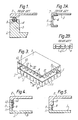
- Figure 1 shows in cross-section a part of a prior art transceiver housing comprising an open-topped box 1 and a lid 2.
- the sealing means comprises a compressible conductive O-ring gasket 3 made, for example, of a metal braid with a sponge rubber core.
- the gasket 3 is seated in a channel 4 located in the top face of side wall 5 of the box 1.
- the lid 2 is fastened down to the box 1, eg. using screws, thus compressing the gasket 3 and forming continuous electrical contact (and hence an effective RF seal) between the lid and the box.
- This prior art transceiver housing does, however, have drawbacks. Firstly, the side wall of the box has to be sufficiently wide to accommodate the sealing gasket 3. Consequently the side wall has to be made thicker than would otherwise be necessary. This necessitates the use of more material for manufacturing the box, which therefore increases the cost, and also results in the box occupying more space. Secondly, the gasket adds further to the expense of the overall housing and, being a separate component, requires an additional step in the assembly of the housing.
- FIG. 2 Another prior art transceiver housing employing a different RFI sealing means is illustrated in Figure 2.
- the leaf springs 6 are suitably formed as a unitary comb-like member as shown in plan view in Figure 2B.
- four such comb-like members 8 would be used, one along each of the four sides of the lid 2.
- This housing arrangement has the advantage that it occupies less space, since the side walls of the box can be made thinner, but manufacture is more costly because of the extra material for the springs and assembly is more difficult and time consuming because of the requirement to attach the individual comb-like members 8 to the lid 2.
- WO 83/01174 discloses as prior art a two-part housing for radio frequency circuitry comprising an open-topped box made of, for example cast aluminium and a cover plate made of a resilient material such as cold rolled steel.
- the cover plate includes integral rectangular-shaped flange projections bent at approximately 90. with respect to the plane of the cover plate.
- the flange projections are shaped with an elbow or ridge which makes electrical contact against the inside walls of the box when the cover plate is press fitted into the opening in the box, thus providing effective RFI sealing. This arrangement relies on the resilience of the flange projections.
- a housing for radio circuitry comprising an open-topped box having bottom and side walls made of electrically conductive material, and a separate electrically conductive lid for closing the box, wherein a plurality of projections depend from the lid and are integral therewith, the width of said projections gradually decreasing away from the lid, which projections are arranged to bear internally against the side walls of the box to prevent radio frequency radiation escaping from the housing.
- the RFI sealing means are provided as projections integral with the lid of the housing. Assembly of the housing is therefore simplified, since the housing comprises only two components, namely the box and the lid, and so there is no separate sealing means to be fitted. Also the housing occupies minimum space since the side walls of the box can be made much thinner than the prior art housing described above with reference to Figure 1. Furthermore, both the box and the lid of a housing in accordance with the invention can suitably be manufactured by diecasting.
- the projections are substantially flat in the plane of the side wall against which they bear.
- the width of the projections gradually decreases away from the lid.
- This arrangement is particularly advantageous since it helps to achieve a better distribution of the stress on the mating parts, specifically the projections.
- the lid made of an inherently rigid material, specifically a diecast metal, such as aluminium. This is remarkable because diecast metals are notoriously brittle and, on the face of it, are therefore not suitable for forming spring features.
- the tapering projections may have various outlines, either curvilinear or rectilinear, or a combination of the two.
- the projections may have a substantially sinusoidal outline or a triangular ("saw-tooth") outline and in either case the peak of the projection may be truncated to leave a flat feature.
- neighbouring projections are in adjoining relationship and to extend around substantially the whole periphery of the lid.
- the projections may, however, extend from a common ridge integral with the lid.
- the projections depend substantially orthogonally to the lid.
- a plurality of ribs is present on the internal side wall of the box, these ribs being arranged to engage and deflect a respective projection on the lid.
- This positive engagement ensures optimum RFI sealing and the preferred tapering profile for the projections enables them to suffer the stress of this deflection without breaking or damage even when they are formed by diecasting.
- Each of the ribs may be provided with a chamfered portion at the end facing the open top of the box. This chamfered portion acts as a guide feature, being arranged to engage the leading edge of the associated projection when the lid is placed on the box.
- the housing shown in Figure 3 is intended for containing the transceiver circuitry of a mobile radio telephone, and comprises a generally rectangular box 1 and a lid 2, both of which may be made of cast aluminium.
- the box 1 comprises a bottom 8 and side walls 5.
- a plurality of adjoining tag-like projections 9 depend from the underside of the lid 2.
- the projections extend from an integral ridge 10, the ridge itself being formed integrally with the lid 2.
- the projections 9 are substantially flat and their width gradually decreases away from the lid.
- the projections have a generally sinusoidal outline, giving a scalloped appearance.
- the curved peak of each projection 9 may be truncated to form a plateau feature.
- the overall dimensions of the box 1 were 25mm in height, 155mm in width and 155mm in depth.
- the lid 2 was therefore 155mm square.
- the thickness of the bottom and side walls of the box 1, and the lid 2 was 15mm and the thickness of the projections 9 was 10mm.
- the height of the ridge 10 was 2mm and the overall length of the projections 9, ie. peak to trough was 10mm.
- the pitch of the projections was 15mm.
- the ridge 10 and depending projections 9 extend around the whole periphery of the lid 2, slightly inset from the edge of the lid so that the projections 9 extend inside the box 1 when the lid is placed on the box 1, as shown most clearly in Figure 4.
- a plurality of ribs 11 is present integrally on the internal face of the side walls 5 of box 1.
- the ribs 11 are arranged to engage a respective projection 9 when the lid 2 is placed on the box.
- the chamfered portion 12 of the rib 11 engages the leading edge of the associated projection 9 which deflects and guides the projection 9 onto the main part of the rib 11.
- the projections 9 exert a spring force on the ribs 11 to provide a continuous and effective RFI seal between the lid and the box.
- the cast aluminium projections 9 are nevertheless capable of suffering the slight deflection which they experience here due to their tapering profile which distributes the stress efficaciously as discussed previously.
- FIG. 5 there is shown a different version of a transceiver housing in accordance with the invention, in which the lid 2 has side walls 13 from which the integral projections 9 depend. As shown, the side walls 13 of the lid 2 are deeper than the side walls 5 of the box 1, but they may instead be substantially equal or smaller.
- box and lid configurations described herein may be inverted so that the so-called “lid” effectively becomes the base of the housing and the "open-topped box” is therefore disposed on top of the lid.
- the outline of the projections need not be sinusoidal but may have a different curved form, or may be rectilinear, or a combination of the two.
- the housing need not be square or rectangular but may, for example, be circular.
- the ribs on the internal face of the side walls of the box may be dispensed with, but in this case it is preferable for the projections 9 on the lid to be inclined at more or less than 90. to provide intimate contact - and hence effective RFI sealing - between the lid and the box.
- the invention is not restricted to a transceiver housing, nor indeed to radiotelephony applications, but may be used for housing any circuitry where there is a risk of generating radio frequency interference.
Landscapes
- Engineering & Computer Science (AREA)
- Computer Networks & Wireless Communication (AREA)
- Signal Processing (AREA)
- Casings For Electric Apparatus (AREA)
- Shielding Devices Or Components To Electric Or Magnetic Fields (AREA)
Applications Claiming Priority (2)
| Application Number | Priority Date | Filing Date | Title |
|---|---|---|---|
| GB8921929A GB2236910B (en) | 1989-09-28 | 1989-09-28 | A housing for electronic circuitry |
| GB8921929 | 1989-09-28 |
Publications (3)
| Publication Number | Publication Date |
|---|---|
| EP0420504A2 true EP0420504A2 (de) | 1991-04-03 |
| EP0420504A3 EP0420504A3 (en) | 1992-03-25 |
| EP0420504B1 EP0420504B1 (de) | 1995-02-01 |
Family
ID=10663764
Family Applications (1)
| Application Number | Title | Priority Date | Filing Date |
|---|---|---|---|
| EP90310310A Expired - Lifetime EP0420504B1 (de) | 1989-09-28 | 1990-09-20 | Gehäuse für Funkgerät |
Country Status (4)
| Country | Link |
|---|---|
| US (1) | US5095177B1 (de) |
| EP (1) | EP0420504B1 (de) |
| DE (1) | DE69016552T2 (de) |
| GB (1) | GB2236910B (de) |
Cited By (8)
| Publication number | Priority date | Publication date | Assignee | Title |
|---|---|---|---|---|
| WO1994019880A1 (en) * | 1993-02-24 | 1994-09-01 | Rosemount Inc. | Transducer with inner conductive cover for emi shielding |
| EP0656692A2 (de) * | 1993-11-26 | 1995-06-07 | Nokia Mobile Phones Ltd. | Abschirmung für ein Funktelefon |
| WO1999014862A1 (en) * | 1997-09-12 | 1999-03-25 | Ericsson, Inc. | Frame structure for cellular telephones |
| EP1001586A2 (de) * | 1998-11-10 | 2000-05-17 | Matsushita Electric Industrial Co., Ltd. | Gehäuse für Funkgerät |
| EP1432298A2 (de) * | 2002-12-18 | 2004-06-23 | Elma Electronic Ag | Gehäuse mit Abdeckplatte |
| EP1579749B1 (de) * | 2002-12-09 | 2008-03-12 | Audioton Kabelwerk GmbH Zweigniederlassung Scheinfeld | Abschirmgehäuse zur Aufnahme einer elektronischen Schaltung |
| US8238984B2 (en) | 2006-04-12 | 2012-08-07 | Funkwerk Dabendorf Gmbh | Device for coupling and housing a mobile telephone in a motor vehicle |
| US9462732B2 (en) | 2013-03-13 | 2016-10-04 | Laird Technologies, Inc. | Electromagnetic interference shielding (EMI) apparatus including a frame with drawn latching features |
Families Citing this family (43)
| Publication number | Priority date | Publication date | Assignee | Title |
|---|---|---|---|---|
| JP2501638Y2 (ja) * | 1991-11-25 | 1996-06-19 | 船井電機株式会社 | プリント基板装着用シ―ルド板 |
| US5369399A (en) * | 1992-05-04 | 1994-11-29 | Motorola, Inc. | Tolerance accumulating circuit supporting mechanical shock isolator |
| US5354951A (en) * | 1993-03-15 | 1994-10-11 | Leader Tech, Inc. | Circuit board component shielding enclosure and assembly |
| US5506373A (en) * | 1993-07-09 | 1996-04-09 | Magnavox Electronic Systems Company | Electronic module enclosure |
| US5536905A (en) * | 1994-04-04 | 1996-07-16 | Motorola, Inc. | Self secured housing for electronics |
| FI103632B (fi) * | 1994-06-16 | 1999-07-30 | Nokia Mobile Phones Ltd | Rf-suoja |
| FI103935B (fi) * | 1994-09-07 | 1999-10-15 | Nokia Mobile Phones Ltd | Menetelmä EMC-suojakotelon kiinnittämiseksi piirilevyyn ja EMC-suojakotelo |
| JP2778502B2 (ja) * | 1995-02-14 | 1998-07-23 | 日本電気株式会社 | 電磁波遮蔽構造体 |
| DE19507846C1 (de) * | 1995-03-07 | 1996-08-08 | Hermann Stahl | Kontaktelement zwischen Gehäuseteilen |
| JPH08335794A (ja) * | 1995-06-08 | 1996-12-17 | Alps Electric Co Ltd | シールドケース |
| US5774344A (en) * | 1995-12-06 | 1998-06-30 | Metricom, Inc. | RF shield for circuit card having a solid first flange |
| DE19636182A1 (de) * | 1996-09-06 | 1998-03-12 | Philips Patentverwaltung | Abschirmgehäuse für elektronische Bauelemente |
| EP0866648B1 (de) * | 1997-03-19 | 2005-01-05 | Telefonaktiebolaget LM Ericsson (publ) | Zweiteilige elektromagnetische Abschirmvorrichtung zur Befestigung auf einer Leiterplatte |
| GB2330953B (en) * | 1997-11-04 | 2002-01-09 | Nec Technologies | Electromagnetic shielding of a PCB |
| US5956925A (en) * | 1997-12-31 | 1999-09-28 | Bmi, Inc. | Carrier tape and method for washing of components in carrier tape |
| KR100296010B1 (ko) | 1998-06-30 | 2001-10-26 | 구본준, 론 위라하디락사 | 휴대용정보처리장치 |
| US6178097B1 (en) | 1999-01-22 | 2001-01-23 | Dial Tool Industries, Inc. | RF shield having removable cover |
| JP2000236189A (ja) * | 1999-02-16 | 2000-08-29 | Minebea Co Ltd | 航空機用電子回路のシールド装置 |
| US6194655B1 (en) | 1999-03-01 | 2001-02-27 | Leader Tech, Inc. | Circuit board component shielding enclosure and assembly having opposing covers interfitted with upper and lower portions of enclosure |
| JP3787454B2 (ja) * | 1999-04-02 | 2006-06-21 | アルプス電気株式会社 | 電子機器 |
| GB2350936B (en) | 1999-06-11 | 2001-08-15 | Marconi Comm Ltd | Enclosure |
| US6320121B1 (en) * | 1999-09-14 | 2001-11-20 | Lucent Technologies Inc. | Radio frequency shield can cover with internal fingers |
| US20030099101A1 (en) * | 2001-10-30 | 2003-05-29 | Skrepcinski Alan J. | Optical network unit with EMI suppression |
| US7095624B2 (en) * | 2004-02-06 | 2006-08-22 | Lucent Technologies Inc. | Electromagnetic shield with vee-slot panel joints |
| US7995355B2 (en) * | 2005-01-10 | 2011-08-09 | Stealthdrive, Inc. | Three-dimensional configurations providing electromagnetic interference shielding for electronics enclosures |
| US7342184B2 (en) * | 2005-03-15 | 2008-03-11 | Stealthdrive, Inc. | Three-dimensional configurations providing electromagnetic interference shielding for electronics enclosures |
| US7491899B2 (en) * | 2005-10-06 | 2009-02-17 | Laird Technologies, Inc. | EMI shields and related manufacturing methods |
| US20080080160A1 (en) * | 2005-12-16 | 2008-04-03 | Laird Technologies, Inc. | Emi shielding assemblies |
| TWM318903U (en) * | 2007-04-03 | 2007-09-11 | Chin-Fu Horng | Electromagnetic shielding device |
| US7504592B1 (en) * | 2007-08-31 | 2009-03-17 | Laird Technologies, Inc. | Electromagnetic interference shields and related manufacturing methods |
| US7687725B2 (en) * | 2008-01-18 | 2010-03-30 | Delphi Technologies, Inc. | Corrosion resistant faraday cage electronic enclosure assembly |
| CN101568250A (zh) * | 2008-04-22 | 2009-10-28 | 深圳富泰宏精密工业有限公司 | 电磁波屏蔽装置 |
| CN101578032B (zh) * | 2008-05-09 | 2011-06-22 | 莱尔德电子材料(深圳)有限公司 | 屏蔽装置和制造屏蔽装置的方法 |
| US7910839B2 (en) * | 2008-11-26 | 2011-03-22 | Itt Manufacturing Enterprises, Inc. | Electro-conductive contact structure for enclosure sealing in housings |
| US10117365B2 (en) | 2015-12-30 | 2018-10-30 | Meps Real-Time, Inc. | Shielded enclosure having tortuous path seal |
| US9832915B2 (en) * | 2016-02-05 | 2017-11-28 | Laird Technologies, Inc. | Pressure locking board level shield assemblies |
| CN107274918B (zh) | 2016-04-07 | 2019-08-16 | 株式会社东芝 | 盘驱动器 |
| TWM556448U (zh) * | 2017-10-06 | 2018-03-01 | Signal Cable System Co Ltd | 防止訊號外洩的電訊分配器外殼 |
| GB2569558B (en) * | 2017-12-19 | 2022-04-06 | Harwin Plc | Element, system and method for retaining a component to a surface |
| USD895623S1 (en) | 2018-10-05 | 2020-09-08 | Laird Technologies, Inc. | Frame for shielding assembly |
| US10653049B2 (en) | 2018-10-05 | 2020-05-12 | Laird Technologies, Inc. | Frames for shielding assemblies and shielding assemblies including the same |
| DE102019214154A1 (de) * | 2019-09-17 | 2021-03-18 | Volkswagen Aktiengesellschaft | Abschirmgehäuse für eine elektrische oder elektronische Fahrzeugkomponente |
| DE102022207527A1 (de) | 2022-07-22 | 2024-01-25 | Volkswagen Aktiengesellschaft | Dichtungsanordnung in einem Elektronikgehäuse |
Citations (5)
| Publication number | Priority date | Publication date | Assignee | Title |
|---|---|---|---|---|
| US3534146A (en) * | 1968-10-24 | 1970-10-13 | Teletype Corp | Double shielded rfi enclosure |
| US3909726A (en) * | 1973-09-26 | 1975-09-30 | Zenith Radio Corp | UHF Hybrid tuner |
| WO1983001174A1 (en) * | 1981-09-14 | 1983-03-31 | Motorola Inc | Radio frequency shield with force multiplier interconnection fingers for an electromagnetic gasket |
| EP0219639A2 (de) * | 1985-10-23 | 1987-04-29 | Robert Bosch Gmbh | Hochfrequenzdichtes Gehäuse |
| US4759466A (en) * | 1986-08-14 | 1988-07-26 | Apple Computer, Inc. | EMI seam for enclosures |
Family Cites Families (4)
| Publication number | Priority date | Publication date | Assignee | Title |
|---|---|---|---|---|
| NL25744C (de) * | 1928-02-25 | |||
| US2627359A (en) * | 1949-05-26 | 1953-02-03 | United Carr Fastener Corp | Housing for electric switches and the like |
| KR890005264Y1 (ko) * | 1986-10-08 | 1989-08-09 | 주식회사 금성사 | 안테나 터미날의 시일드 케이스 |
| JPH0298797A (ja) * | 1988-10-04 | 1990-04-11 | Mitsubishi Electric Corp | 飲食店サービスシステム |
-
1989
- 1989-09-28 GB GB8921929A patent/GB2236910B/en not_active Expired - Fee Related
-
1990
- 1990-09-20 DE DE69016552T patent/DE69016552T2/de not_active Expired - Fee Related
- 1990-09-20 EP EP90310310A patent/EP0420504B1/de not_active Expired - Lifetime
- 1990-09-20 US US07585882 patent/US5095177B1/en not_active Expired - Lifetime
Patent Citations (5)
| Publication number | Priority date | Publication date | Assignee | Title |
|---|---|---|---|---|
| US3534146A (en) * | 1968-10-24 | 1970-10-13 | Teletype Corp | Double shielded rfi enclosure |
| US3909726A (en) * | 1973-09-26 | 1975-09-30 | Zenith Radio Corp | UHF Hybrid tuner |
| WO1983001174A1 (en) * | 1981-09-14 | 1983-03-31 | Motorola Inc | Radio frequency shield with force multiplier interconnection fingers for an electromagnetic gasket |
| EP0219639A2 (de) * | 1985-10-23 | 1987-04-29 | Robert Bosch Gmbh | Hochfrequenzdichtes Gehäuse |
| US4759466A (en) * | 1986-08-14 | 1988-07-26 | Apple Computer, Inc. | EMI seam for enclosures |
Non-Patent Citations (1)
| Title |
|---|
| HEWLETT-PACKARD JOURNAL vol. 36, no. 12, December 1985, AMSTELVEEN NL pages 14 - 18; JEWELL, JOHNSON: 'Internally Modular Signal Generator Design' * |
Cited By (14)
| Publication number | Priority date | Publication date | Assignee | Title |
|---|---|---|---|---|
| WO1994019880A1 (en) * | 1993-02-24 | 1994-09-01 | Rosemount Inc. | Transducer with inner conductive cover for emi shielding |
| EP0656692A3 (de) * | 1993-11-26 | 1999-10-13 | Nokia Mobile Phones Ltd. | Abschirmung für ein Funktelefon |
| EP0656692A2 (de) * | 1993-11-26 | 1995-06-07 | Nokia Mobile Phones Ltd. | Abschirmung für ein Funktelefon |
| AU744218B2 (en) * | 1997-09-12 | 2002-02-21 | Ericsson Inc. | Frame structure for cellular telephones |
| US6058293A (en) * | 1997-09-12 | 2000-05-02 | Ericsson, Inc. | Frame structure for cellular telephones |
| WO1999014862A1 (en) * | 1997-09-12 | 1999-03-25 | Ericsson, Inc. | Frame structure for cellular telephones |
| EP1001586A2 (de) * | 1998-11-10 | 2000-05-17 | Matsushita Electric Industrial Co., Ltd. | Gehäuse für Funkgerät |
| EP1001586A3 (de) * | 1998-11-10 | 2003-11-05 | Matsushita Electric Industrial Co., Ltd. | Gehäuse für Funkgerät |
| EP1579749B1 (de) * | 2002-12-09 | 2008-03-12 | Audioton Kabelwerk GmbH Zweigniederlassung Scheinfeld | Abschirmgehäuse zur Aufnahme einer elektronischen Schaltung |
| EP1432298A2 (de) * | 2002-12-18 | 2004-06-23 | Elma Electronic Ag | Gehäuse mit Abdeckplatte |
| EP1432298A3 (de) * | 2002-12-18 | 2005-07-06 | Elma Electronic Ag | Gehäuse mit Abdeckplatte |
| US8238984B2 (en) | 2006-04-12 | 2012-08-07 | Funkwerk Dabendorf Gmbh | Device for coupling and housing a mobile telephone in a motor vehicle |
| US9462732B2 (en) | 2013-03-13 | 2016-10-04 | Laird Technologies, Inc. | Electromagnetic interference shielding (EMI) apparatus including a frame with drawn latching features |
| US10021817B2 (en) | 2013-03-13 | 2018-07-10 | Laird Technologies, Inc. | Electromagnetic interference shielding (EMI) apparatus including a frame with drawn latching features |
Also Published As
| Publication number | Publication date |
|---|---|
| US5095177A (en) | 1992-03-10 |
| US5095177B1 (en) | 1994-08-23 |
| EP0420504A3 (en) | 1992-03-25 |
| GB2236910B (en) | 1993-12-08 |
| GB8921929D0 (en) | 1989-11-15 |
| DE69016552D1 (de) | 1995-03-16 |
| EP0420504B1 (de) | 1995-02-01 |
| GB2236910A (en) | 1991-04-17 |
| DE69016552T2 (de) | 1995-10-05 |
Similar Documents
| Publication | Publication Date | Title |
|---|---|---|
| EP0420504B1 (de) | Gehäuse für Funkgerät | |
| GB2252677A (en) | RFI screened housing for electronic circuitry | |
| US6377472B1 (en) | Shielding device | |
| US6178097B1 (en) | RF shield having removable cover | |
| US7746666B2 (en) | Shield case | |
| US5748455A (en) | Electromagnetic shield for a radiotelephone | |
| EP0088115B1 (de) | Hf-abschirmung mit kraftverstärkenden verbindungsfingern für einen elektromagnetischen dichtungsring | |
| US6320121B1 (en) | Radio frequency shield can cover with internal fingers | |
| US5015802A (en) | Computer casing connector | |
| JP4777962B2 (ja) | 電磁干渉シールド及びその製造方法 | |
| US6252160B1 (en) | I/O shield for electronic assemblies | |
| US6274808B1 (en) | EMI shielding enclosure | |
| AU7545391A (en) | Electromagnetic shield for electrical circuit | |
| JPH05183287A (ja) | 電子装置を高周波遮蔽ハウジングに差込むための組立体 | |
| US6379196B1 (en) | Terminal connector for a circuit breaker | |
| EP0661918A1 (de) | Gehäuse für elektronisches Bauelement zur elektromagnetischen Abschirmung | |
| CA1286011C (en) | Electrical outlet receptacle with non-metallic mounting strap and automatic grounding | |
| US20030102786A1 (en) | Cabinet structure of electronic device with the structure | |
| US5484309A (en) | Electrical receptacle assembly with interference fitting and latching parts | |
| CA1061443A (en) | High frequency electrical shield assembly | |
| CA2394993C (en) | Mounting formation for an electrical outlet box | |
| US9113548B2 (en) | Device and method for a signal shield | |
| GB1584320A (en) | Electric grill assembly for killing insects | |
| EP1059834A2 (de) | Gehäuse | |
| MY116839A (en) | Push-button switch |
Legal Events
| Date | Code | Title | Description |
|---|---|---|---|
| PUAI | Public reference made under article 153(3) epc to a published international application that has entered the european phase |
Free format text: ORIGINAL CODE: 0009012 |
|
| AK | Designated contracting states |
Kind code of ref document: A2 Designated state(s): DE GB IT SE |
|
| PUAL | Search report despatched |
Free format text: ORIGINAL CODE: 0009013 |
|
| AK | Designated contracting states |
Kind code of ref document: A3 Designated state(s): DE GB IT SE |
|
| 17P | Request for examination filed |
Effective date: 19920619 |
|
| RAP1 | Party data changed (applicant data changed or rights of an application transferred) |
Owner name: NOKIA MOBILE PHONES (U.K.) LIMITED |
|
| 17Q | First examination report despatched |
Effective date: 19931108 |
|
| GRAA | (expected) grant |
Free format text: ORIGINAL CODE: 0009210 |
|
| AK | Designated contracting states |
Kind code of ref document: B1 Designated state(s): DE GB IT SE |
|
| REF | Corresponds to: |
Ref document number: 69016552 Country of ref document: DE Date of ref document: 19950316 |
|
| ITF | It: translation for a ep patent filed |
Owner name: MODIANO & ASSOCIATI S.R.L. |
|
| PLBE | No opposition filed within time limit |
Free format text: ORIGINAL CODE: 0009261 |
|
| STAA | Information on the status of an ep patent application or granted ep patent |
Free format text: STATUS: NO OPPOSITION FILED WITHIN TIME LIMIT |
|
| 26N | No opposition filed | ||
| REG | Reference to a national code |
Ref country code: GB Ref legal event code: IF02 |
|
| PGFP | Annual fee paid to national office [announced via postgrant information from national office to epo] |
Ref country code: GB Payment date: 20050914 Year of fee payment: 16 |
|
| GBPC | Gb: european patent ceased through non-payment of renewal fee |
Effective date: 20060920 |
|
| PG25 | Lapsed in a contracting state [announced via postgrant information from national office to epo] |
Ref country code: GB Free format text: LAPSE BECAUSE OF NON-PAYMENT OF DUE FEES Effective date: 20060920 |
|
| PGFP | Annual fee paid to national office [announced via postgrant information from national office to epo] |
Ref country code: IT Payment date: 20080926 Year of fee payment: 19 |
|
| PGFP | Annual fee paid to national office [announced via postgrant information from national office to epo] |
Ref country code: DE Payment date: 20081002 Year of fee payment: 19 |
|
| PGFP | Annual fee paid to national office [announced via postgrant information from national office to epo] |
Ref country code: SE Payment date: 20080908 Year of fee payment: 19 |
|
| EUG | Se: european patent has lapsed | ||
| PG25 | Lapsed in a contracting state [announced via postgrant information from national office to epo] |
Ref country code: DE Free format text: LAPSE BECAUSE OF NON-PAYMENT OF DUE FEES Effective date: 20100401 |
|
| PG25 | Lapsed in a contracting state [announced via postgrant information from national office to epo] |
Ref country code: IT Free format text: LAPSE BECAUSE OF NON-PAYMENT OF DUE FEES Effective date: 20090920 |
|
| PG25 | Lapsed in a contracting state [announced via postgrant information from national office to epo] |
Ref country code: SE Free format text: LAPSE BECAUSE OF NON-PAYMENT OF DUE FEES Effective date: 20090921 |