EP0417423A2 - Circuit for the determination of the rotational speed of a wheel - Google Patents
Circuit for the determination of the rotational speed of a wheel Download PDFInfo
- Publication number
- EP0417423A2 EP0417423A2 EP90113395A EP90113395A EP0417423A2 EP 0417423 A2 EP0417423 A2 EP 0417423A2 EP 90113395 A EP90113395 A EP 90113395A EP 90113395 A EP90113395 A EP 90113395A EP 0417423 A2 EP0417423 A2 EP 0417423A2
- Authority
- EP
- European Patent Office
- Prior art keywords
- wheel
- output
- speed
- circuit according
- circuit
- Prior art date
- Legal status (The legal status is an assumption and is not a legal conclusion. Google has not performed a legal analysis and makes no representation as to the accuracy of the status listed.)
- Withdrawn
Links
Images
Classifications
-
- G—PHYSICS
- G01—MEASURING; TESTING
- G01P—MEASURING LINEAR OR ANGULAR SPEED, ACCELERATION, DECELERATION, OR SHOCK; INDICATING PRESENCE, ABSENCE, OR DIRECTION, OF MOVEMENT
- G01P21/00—Testing or calibrating of apparatus or devices covered by the preceding groups
- G01P21/02—Testing or calibrating of apparatus or devices covered by the preceding groups of speedometers
-
- G—PHYSICS
- G01—MEASURING; TESTING
- G01P—MEASURING LINEAR OR ANGULAR SPEED, ACCELERATION, DECELERATION, OR SHOCK; INDICATING PRESENCE, ABSENCE, OR DIRECTION, OF MOVEMENT
- G01P3/00—Measuring linear or angular speed; Measuring differences of linear or angular speeds
- G01P3/42—Devices characterised by the use of electric or magnetic means
- G01P3/44—Devices characterised by the use of electric or magnetic means for measuring angular speed
- G01P3/48—Devices characterised by the use of electric or magnetic means for measuring angular speed by measuring frequency of generated current or voltage
- G01P3/481—Devices characterised by the use of electric or magnetic means for measuring angular speed by measuring frequency of generated current or voltage of pulse signals
- G01P3/488—Devices characterised by the use of electric or magnetic means for measuring angular speed by measuring frequency of generated current or voltage of pulse signals delivered by variable reluctance detectors
Definitions
- the invention relates to a circuit for determining the speed of a wheel with an inductive sensor, the output of which is connected to a pulse shaping device, the output of which is connected to an evaluation device.
- inductive sensors In motor vehicles, it may be necessary, for example for an anti-lock braking system, to record the wheel speed or the speed of a wheel.
- inductive sensors are used, in which a periodically changing magnetic conductance, for example a ring gear arranged concentrically to the wheel and rotating synchronously with the wheel, induces a sine-like voltage, the frequency of which is proportional to the speed of the wheel.
- the approximately sinusoidal voltage is further processed by downstream electronics, which result from the voltage Rectangular pulses generated. From the time interval between certain sizes of the square-wave pulses, for example the rising edges, a statement about the speed of the wheel in question can be obtained with the aid of a digital processing device. Since the voltage generated in inductive sensors is proportional to the change in the magnetic field over time, the output voltage of an inductive sensor is very dependent on the frequency. The higher the frequency, the greater the amplitude of the output signal.
- the inductive sensors Since the inductive sensors have to be arranged directly on the wheel, they are increasingly exposed to environmental influences. They are polluted by street dirt and moisture and are subjected to high mechanical loads due to vibrations. The vibrations can, for example, change the distance of the encoder from the ring gear or lead to the breaking of an electrical line.
- the voltage generated by the inductive transmitter is generally not evaluated directly on the wheel, but in a central evaluation device to which the voltage is transmitted using electrical lines.
- the soiling can lead to so-called dirt resistances, which form a leakage current path between the two wires of a line.
- the dirt resistors make fault diagnosis difficult, which in some way evaluates the voltage drop across the ohmic internal resistance of the inductive sensor. This occurs when a direct current is impressed on the encoder. The voltage drop then considerably reduces the sensitivity of the pulse shaper circuit if the DC potential at the sensor is not decoupled from that at the pulse shaper device.
- the auxiliary device advantageously evaluates the amplitude of an output voltage present at the output of the inductive transmitter.
- the amplitude is a measure of the speed of the wheel. The higher the speed of the wheel, the greater the amplitude of the output voltage. Even if there is no linear relationship here, the evaluation of the amplitude is sufficient to influence the internal resistance and thus the sensitivity of the pulse shaping device sufficiently.
- the auxiliary device can also evaluate the frequency of the output voltage.
- the frequency is directly proportional to the speed.
- information can be drawn about possible dirt resistance and other currents, such as permanent changes in the air gap in the encoder.
- the auxiliary device advantageously changes an input resistance of the pulse shaping device.
- the easiest way to intervene in the internal resistance of the pulse shaping device is at the input.
- the remaining pulse shaping device can then be left unchanged.
- the pulse shaping device has a comparator connected as a Schmitt trigger and the input resistance influences the level of the voltage applied to the comparator.
- the auxiliary device has a switching element which, when a predetermined speed of the wheel is exceeded, connects a parallel resistor in parallel with the input resistance of the pulse shaping device. This results in a higher voltage drop across the ohmic internal resistance of the inductive encoder. The voltage applied to the comparator is thereby reduced. It is thus possible to check both the line to the inductive sensor for interruption and the correct function of the inductive sensor, for example the correct distance of the sensor from the ring gear, by connecting the parallel resistor.
- the switching element is advantageously designed as a transistor.
- the entire circuit can thus be carried out without mechanical elements.
- the auxiliary device has a microprocessor.
- the microprocessor can simultaneously be used to convert the pulses emitted by the pulse shaping device into the rotational speed of the wheel. Since information about the rotational speed of the wheel is thus already available, the microprocessor can also be used advantageously for controlling the switching element of the auxiliary device.
- a pulse generator 1 has a ring gear 2 which runs past a core 4 connected to a magnet 3 when a wheel (not shown) rotates.
- a coil 5 is wound around the core 4.
- the teeth of the ring gear 2 pass the core 4, the magnetic conductance of the magnetic circuit changes and thus the magnetic flux generated by the magnet 3 in the core 4.
- the change in the magnetic flux induces a current in the coil, which generates a voltage across a resistor R A.
- This voltage is fed to an evaluation device 11 via a two-wire line 6.
- dirt deposits on the surface so-called dirt deposits on the surface called “dirt resistance", that is, leakage current paths.
- Such dirt resistance is shown in dashed lines as resistance R S.
- the evaluation device 11 has a pulse shaper device 7, which turns the essentially sinusoidal output voltage of the inductive transmitter 1, which is supplied via the line 6 to the evaluation device 11, into a pulse train which is supplied to a microprocessor 9.
- the evaluation device 7 has a comparator 8 connected as a Schmitt trigger.
- the non-inverting input of the comparator 8 is connected via a resistor R2 to a potential P A formed by a voltage divider R3 / R4 at point A.
- the non-inverting input of the comparator 8 is connected to the output of the comparator via a resistor R7.
- the inverting input of the comparator 8 is connected via a resistor R1 to a potential P B , which changes essentially sinusoidally as a function of the voltage generated by the inductive transmitter 1 and of a resistor R6 (see FIG. 2).
- the potential P B is also supplied to the microprocessor 9 via a line 12. This evaluates the voltage at point B, for example determines the amplitude or frequency of the voltage. Both variables provide information about the number of revolutions of the ring gear 2 and thus about the number of revolutions of the wheel that is to be determined.
- a resistor R5 in parallel to the higher-resistance resistor R6. This reduces the internal resistance of the pulse shaping device and reduces its "sensitivity".
- Fig. 2 shows two voltages generated by the inductive transmitter 1, namely once the voltage 5, which at a fast wheel speed, i.e. a high number of revolutions is generated, and the voltage L, which at a slow wheel speed, i.e. a low revolution count of the wheel is generated. If the comparison voltage of the comparator 8 were left unchanged even at slow speeds, the comparator would no longer generate pulses at low speeds. On the other hand, if the low comparison voltage were to remain constant even at high wheel speeds, there would be no way to check whether the inductive transmitter 1 is still working correctly or is still connected.
Abstract
Es wird eine Schaltung zur Ermittlung der Drehzahl eines Rades mit einem induktiven Geber (1) angegeben, dessen Ausgang mit einer Impulsformereinrichtung (7) verbunden ist, deren Ausgang mit einer Auswerteeinrichtung verbunden ist. Der induktive Geber (1) ist mit Hilfe einer Leitung (6) mit einer Auswerteschaltung (11) verbunden. Die Auswerteschaltung (11) soll einerseits sicherstellen, daß das Ausgangssignal des induktiven Gebers (1) ausgewertet werden kann, andererseits soll sie in der Lage sein, Fehler, die beispielsweise durch einen Abriß der Leitung (6) auftreten können, trotz Vorhandensein von Schmutzwiderständen (RS) zu erkennen. Dazu ist eine Hilfseinrichtung (10) vorgesehen, die den Innenwiderstand der Impulsformereinrichtung (7) geschwindigkeitsabhängig verändert. <IMAGE>The invention relates to a circuit for determining the speed of a wheel with an inductive transmitter (1), the output of which is connected to a pulse shaping device (7), the output of which is connected to an evaluation device. The inductive transmitter (1) is connected to an evaluation circuit (11) by means of a line (6). The evaluation circuit (11) is intended on the one hand to ensure that the output signal of the inductive sensor (1) can be evaluated, and on the other hand it should be able to detect errors which may occur, for example, due to a line break (6), despite the presence of dirt resistors ( RS). For this purpose, an auxiliary device (10) is provided which changes the internal resistance of the pulse shaping device (7) as a function of the speed. <IMAGE>
Description
Die Erfindung betrifft eine Schaltung zur Ermittlung der Drehzahl eines Rades mit einem induktiven Geber, dessen Ausgang mit einer Impulsformereinrichtung verbunden ist, deren Ausgang mit einer Auswerteeinrichtung verbunden ist.The invention relates to a circuit for determining the speed of a wheel with an inductive sensor, the output of which is connected to a pulse shaping device, the output of which is connected to an evaluation device.
In Kraftfahrzeugen kann es, beispielsweise für ein Anti-Blockier-System, notwendig werden, die Radgeschwindigkeit oder die Drehzahl eines Rades zu erfassen. Dazu werden induktive Geber verwendet, in denen durch einen sich periodisch ändernden magnetischen Leitwert, beispielsweise ein konzentrisch zum Rad angeordneter und sich mit dem Rad synchron drehender Zahnkranz, eine sinusähnliche Spannung induziert wird, deren Frequenz der Drehzanl des Rades proportional ist. Die annähernd sinusförmige Spannung wird durch eine nachgeschaltete Elektronik weiterverarbeitet, die aus der Spannung eine Folge von Rechteckimpulsen erzeugt. Aus dem zeitlichen Abstand von bestimmten Größen der Rechteckimpulse, beispielsweise der steigenden Flanken, läßt sich mit Hilfe einer digitalen Verarbeitungseinrichtung eine Aussage über die Drehzahl des betreffenden Rades gewinnen. Da die in induktiven Gebern erzeugte Spannung proportional zur Anderung des Magnetfeldes über der Zeit ist, ist die Ausgangsspannung eines induktiven Gebers sehr stark von der Frequenz abhängig. Je höher die Frequenz ist, desto größer ist die Amplitude des Ausgangssignals.In motor vehicles, it may be necessary, for example for an anti-lock braking system, to record the wheel speed or the speed of a wheel. For this purpose, inductive sensors are used, in which a periodically changing magnetic conductance, for example a ring gear arranged concentrically to the wheel and rotating synchronously with the wheel, induces a sine-like voltage, the frequency of which is proportional to the speed of the wheel. The approximately sinusoidal voltage is further processed by downstream electronics, which result from the voltage Rectangular pulses generated. From the time interval between certain sizes of the square-wave pulses, for example the rising edges, a statement about the speed of the wheel in question can be obtained with the aid of a digital processing device. Since the voltage generated in inductive sensors is proportional to the change in the magnetic field over time, the output voltage of an inductive sensor is very dependent on the frequency. The higher the frequency, the greater the amplitude of the output signal.
Da die induktiven Geber unmittelbar am Rad angeordnet sein müssen, sind sie in verstärktem Maße Umwelteinflüssen ausgesetzt. Sie werden durch Straßendreck und Feuchtigkeit verschmutzt und durch Erschütterungen mechanisch stark belastet. Die Erschütterungen können beispielsweise den Abstand des Gebers vom Zahnkranz ändern oder zum Abriß einer elektrischen Leitung führen. Die Auswertung der durch den induktiven Geber erzeugten Spannung erfolgt in der Regel nicht unmittelbar am Rad, sondern in einer zentralen Auswerteeinrichtung, zu der die Spannung mit Hilfe von elektrischen Leitungen übertragen wird. Durch die Verschmutzung kann es zu sogenannten Schmutzwiderständen kommen, die eine Kriechstromstrecke zwischen den beiden Adern einer Leitung bilden. Die Schmutzwiderstände erschweren die Fehler-Diagnose, die auf irgendeine Art und Weise den Spannungsabfall über den ohmschen Innenwiderstand des induktiven Gebers auswertet. Dieser entsteht, wenn auf den Geber ein Gleichstrom eingeprägt wird. Der Spannungsabfall verringert dann die Empfindlichkeit der Impulsformerschaltung erheblich, wenn keine Abkopplung des Gleichpotentials am Sensor von dem an der Impulsformereinrichtung erfolgt.Since the inductive sensors have to be arranged directly on the wheel, they are increasingly exposed to environmental influences. They are polluted by street dirt and moisture and are subjected to high mechanical loads due to vibrations. The vibrations can, for example, change the distance of the encoder from the ring gear or lead to the breaking of an electrical line. The voltage generated by the inductive transmitter is generally not evaluated directly on the wheel, but in a central evaluation device to which the voltage is transmitted using electrical lines. The soiling can lead to so-called dirt resistances, which form a leakage current path between the two wires of a line. The dirt resistors make fault diagnosis difficult, which in some way evaluates the voltage drop across the ohmic internal resistance of the inductive sensor. This occurs when a direct current is impressed on the encoder. The voltage drop then considerably reduces the sensitivity of the pulse shaper circuit if the DC potential at the sensor is not decoupled from that at the pulse shaper device.
Es ist die Aufgabe der vorliegenden Erfindung, eine Schaltung anzugeben, die einerseits auch bei langsamen Radgeschwindigkeiten ausreichend empfindlich reagieren kann, andererseits aber auch Fehler genau genug erfassen kann.It is the object of the present invention to provide a circuit which, on the one hand, can react sufficiently sensitively even at slow wheel speeds, but on the other hand can also detect errors with sufficient accuracy.
Diese Aufgabe wird bei einer Schaltung der eingangs genannten Art dadurch gelöst, daß eine Hilfseinrichtung vorgesehen ist, die den Innenwiderstand der Impulsformereinrichtung geschwindigkeitsabhängig verändert.This object is achieved in a circuit of the type mentioned in the introduction in that an auxiliary device is provided which changes the internal resistance of the pulse shaping device as a function of the speed.
Dadurch ist es möglich, bei höheren Geschwindigkeiten, d.h. wenn das Ausgangssignal des induktiven Gebers eine größere Amplitude aufweist, eine Kontrolle der Anordnung auf Leitungsunterbrechungen durchzuführen. Die Schmutzwiderstände, die normalerweise einen geschlossenen Stromkreislauf erzeugen und damit eine intakte Leitung vortäuschen, können dann mit hoher Sicherheit erkannt werden. Umgekehrt wird bei einer kleineren Geschwindigkeit, d.h. wenn die Amplitude der Ausgangsspannung des induktiven Gebers niedrig ist, der Innenwiderstand verändert und damit die Empfindlichkeit der Impulsformereinrichtung heraufgesetzt. Dann ist zwar keine Erkennung der Schmutzwiderstände möglich. Diese Erkennung muß aber nicht permanent erfolgen.This makes it possible to operate at higher speeds, i.e. if the output signal of the inductive transmitter has a larger amplitude, check the arrangement for line interruptions. The dirt resistances, which normally create a closed circuit and thus simulate an intact line, can then be detected with a high degree of certainty. Conversely, at a lower speed, i.e. if the amplitude of the output voltage of the inductive transmitter is low, the internal resistance changes and thus increases the sensitivity of the pulse shaping device. Then no detection of dirt resistance is possible. However, this detection does not have to be permanent.
Mit Vorteil wertet die Hilfseinrichtung die Amplitude einer am Ausgang des induktiven Gebers anliegenden Ausgangsspannung aus. Wie eingangs ausgeführt, ist die Amplitude ein Maß für die Drehzanl des Rades. Je höher die Drehzahl des Rades ist, desto größer ist die Amplitude der Ausgangsspannung. Auch wenn hier kein linearer Zusammenhang vorliegt, reicht die Auswertung der Höhe der Amplitude aus, um den Innenwiderstand und damit die Empfindlichkeit der Impulsformereinrichtung ausreichend stark zu beeinflussen.The auxiliary device advantageously evaluates the amplitude of an output voltage present at the output of the inductive transmitter. As stated at the beginning, the amplitude is a measure of the speed of the wheel. The higher the speed of the wheel, the greater the amplitude of the output voltage. Even if there is no linear relationship here, the evaluation of the amplitude is sufficient to influence the internal resistance and thus the sensitivity of the pulse shaping device sufficiently.
Die Hilfseinrichtung kann auch die Frequenz der Ausgangsspannung auswerten. Die Frequenz ist direkt der Geschwindigkeit proportional. Insbesondere, wenn Frequenz und Spannung zusammen ausgewertet werden, lassen sich Aufschlüsse über möglicherweise vorhandene Schmutzwiderstände und andere Strömungen, wie bleibende Veränderungen des Luftspalts im Geber, ziehen.The auxiliary device can also evaluate the frequency of the output voltage. The frequency is directly proportional to the speed. In particular, if frequency and voltage are evaluated together, information can be drawn about possible dirt resistance and other currents, such as permanent changes in the air gap in the encoder.
Vorteilhafterweise verändert die Hilfseinrichtung einen Eingangswiderstand der Impulsformereinrichtung. Der Eingriff in den Innenwiderstand der Impulsformereinrichtung ist am Eingang am einfachsten. Die übrige Impulsformereinrichtung kann dann unverändert belassen werden.The auxiliary device advantageously changes an input resistance of the pulse shaping device. The easiest way to intervene in the internal resistance of the pulse shaping device is at the input. The remaining pulse shaping device can then be left unchanged.
In einer bevorzugten Ausführungsform weist die Impulsformereinrichtung einen als Schmitt-Trigger beschalteten Komparator auf und der Eingangswiderstand beeinflußt die Höhe der am Komparator anliegenden Spannung.In a preferred embodiment, the pulse shaping device has a comparator connected as a Schmitt trigger and the input resistance influences the level of the voltage applied to the comparator.
In einer bevorzugten Ausführungsform weist die Hilfseinrichtung ein Schaltelement auf, das bei Überschreiten einer vorbestimmten Drehzahl des Rades dem Eingangswiderstand der Impulsformereinrichtung einen Parallelwiderstand parallel schaltet. Damit ergibt sich ein höherer Spannungsabfall über den ohmschen Innenwiderstand des induktiven Gebers. Die Spannung, die am Komparator anliegt, wird dadurch abgesenkt. Damit ist es möglich durch Zuschalten des Parallelwiderstandes sowohl die Leitung zum induktiven Geber auf Unterbrechung als auch die korrekte Funktion des induktiven Gebers, beispielsweise den richtigen Abstand des Gebers von dem Zahnkranz, zu überprüfen.In a preferred embodiment, the auxiliary device has a switching element which, when a predetermined speed of the wheel is exceeded, connects a parallel resistor in parallel with the input resistance of the pulse shaping device. This results in a higher voltage drop across the ohmic internal resistance of the inductive encoder. The voltage applied to the comparator is thereby reduced. It is thus possible to check both the line to the inductive sensor for interruption and the correct function of the inductive sensor, for example the correct distance of the sensor from the ring gear, by connecting the parallel resistor.
Mit Vorteil ist das Schaltelement als Transistor ausgebildet. Damit läßt sich die ganze Schaltung ohne mechanische Elemente ausführen.The switching element is advantageously designed as a transistor. The entire circuit can thus be carried out without mechanical elements.
In einer bevorzugten Ausführungsform weist die Hilfseinrichtung einen Mikroprozessor auf. Der Mikroprozessor kann gleichzeitig dafür verwendet werden, die von der Impulsformereinrichtung abgegebenen Impulse in die Drehzähl des Rades umzuwandeln. Nachdem damit bereits eine Information über die Drehzähl des Rades zur Verfügung steht, läßt sich der Mikroprozessor mit Vorteil auch für die Steuerung des Schaltelements der Hilfseinrichtung verwenden.In a preferred embodiment, the auxiliary device has a microprocessor. The microprocessor can simultaneously be used to convert the pulses emitted by the pulse shaping device into the rotational speed of the wheel. Since information about the rotational speed of the wheel is thus already available, the microprocessor can also be used advantageously for controlling the switching element of the auxiliary device.
Die Erfindung wird im folgenden anhand eines bevorzugten Ausführungsbeispiels in Verbindung mit der Zeichnung beschrieben. Darin zeigen:
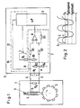
- Fig. 1 eine Schaltungsanordnung und
- Fig. 2 einen schematisch dargestellten Spannungsverlauf.
- Fig. 1 shows a circuit arrangement and
- Fig. 2 shows a schematically illustrated voltage curve.
Ein Impulsgeber 1 weist einen Zahnkranz 2 auf, der an einem mit einem Magneten 3 verbundenen Kern 4 vorbeiläuft, wenn sich ein nicht dargestelltes Rad dreht. Um den Kern 4 ist eine Spule 5 gewickelt. Beim Vorbeilaufen der Zähne des Zahnkranzes 2 am Kern 4 ändert sich der magnetische Leitwert des magnetischen Kreises und damit der durch den Magneten 3 im Kern 4 erzeugte magnetische Fluß. Die Anderung des magnetischen Flusses induziert in der Spule einen Strom, der an einem Widerstand RA eine Spannung erzeugt. Diese Sapnnung wird über eine zweiadrige Leitung 6 einer Auswerteeinrichtung 11 zugeführt. Zwischen den Anschlüssen der Leitung 6 können sich durch Schmutzablagerungen an der Oberfläche soge nannte "Schmutzwiderstände", also Kriechstromstrecken, bilden. Ein solcher Schmutzwiderstand ist als Widerstand RS gestrichelt eingezeichnet. Ein solcher Schmutzwiderstand RS erschwert es der Auswerteeinrichtung 11, zu erkennen, ob die Leitung 6 abgerissen worden ist oder nicht. Auch wenn die Leitung 6 abgerissen ist, d.h. elektrisch unterbrochen ist, läßt sich über den Widerstand RS immer noch ein Strom von einer Ader zu anderen Ader der Leitung 6 leiten.A pulse generator 1 has a ring gear 2 which runs past a core 4 connected to a
Die Auswerteeinrichtung 11 weist eine Impulsformereinrichtung 7 auf, die aus der im wesentlichen sinusförmigen Ausgangsspannung des induktiven Gebers 1, die über die Leitung 6 der Auswerteeinrichtung 11 zugeführt wird, einen Impulszug macht, der einem Mikroprozessor 9 zugeführt wird. Die Auswerteeinrichtung 7 weist einen als Schmitt-Trigger beschalteten Komparator 8 auf. Der nicht invertierende Eingang des Komparators 8 ist über einen Widerstand R2 auf ein durch einen Spannungsteiler R3/R4 am Punkt A gebildetes Potential PA gelegt. Weiterhin ist der nicht invertierende Eingang des Komparators 8 über einen Widerstand R7 mit dem Ausgang des Komparators verbunden. Der invertierende Eingang des Komparators 8 ist über einen Widerstand R1 an ein Potential PB gelegt, das sich in Abhängigkeit von der vom induktiven Geber 1 erzeugten Spannung und von einem Widerstand R6 im wesentlichen sinusförmig ändert (siehe Fig. 2).The
Das Potential PB wird über eine Leitung 12 auch dem Mikroprozessor 9 zugeführt. Dieser wertet die Spannung am Punkt B aus, ermittelt also beispielsweise die Amplitude oder die Frequenz der Spannung. Beide Größen geben Aufschluß über die Umdrehungszanl des Zähnkranzes 2 und damit über die Umdrehungszahl des Rades, die ermittelt werden soll. Um bei Vorhandensein eventueller Schmutzwiderstände RS an den Anschlüssen des induktiven Gebers einen Abriß der Leitung 6 erkennen zu können, wird bei Frequenzen oder Amplituden oberhalb eines vorbestimmten Schwellwertes mittels eines als Transistor T ausgebildeten analogen Schalters ein Widerstand R5 parallel zum hochohmigeren Widerstand R6 geschaltet. Damit wird der Innenwiderstand der Impulsformereinrichtung vermindert und ihre "Empfindlichkeit" herabgesetzt. Der dann höhere Spannungsabfall über den ohmschen Innenwiderstand des induktiven Gebers 1 bleibt bei sonst korrekter Funktion des induktiven Gebers 1, z.B. richtiger Abstand des Kerns 4 zum Zahnkranz 2, keine Kurzschlüsse oder Unterbrechungen, ohne Auswirkung auf das Ausgangssignal des Komparators 8. Somit ist es möglich, durch Zuschalten des Widerstandes R5 die "Empfindlichkeit" des Komparators herabzusetzen.The potential P B is also supplied to the microprocessor 9 via a
Fig. 2 zeigt zwei vom induktiven Geber 1 erzeugte Spannungen, nämlich einmal die Spannung 5, die bei einer schnellen Radgeschwindigkeit, d.h. einer hohen Umdrehungszahl, erzeugt wird, und die Spannung L, die bei einer langsamen Radgeschwindigkeit, d.h. einer niedrigen Umdrehungszähl des Rades erzeugt wird. Würde man die Vergleichsspannung des Komparators 8 auch bei langsamen Geschwindigkeiten unverändert belassen, würde der Komparator bei niedrigen Umdrehungszahlen keine Impulse mehr erzeugen. Würde man andererseits die niedrige Vergleichsspannung auch bei hohen Geschwindigkeiten des Rades konstant lassen, hätte man keine Möglichkeit mehr, zu überprüfen, ob der induktive Geber 1 noch korrekt arbeitet oder überhaupt noch angeschlossen ist.Fig. 2 shows two voltages generated by the inductive transmitter 1, namely once the
Claims (8)
Applications Claiming Priority (2)
| Application Number | Priority Date | Filing Date | Title |
|---|---|---|---|
| DE3930895A DE3930895A1 (en) | 1989-09-15 | 1989-09-15 | CIRCUIT FOR DETECTING THE SPEED OF A WHEEL |
| DE3930895 | 1989-09-15 |
Publications (2)
| Publication Number | Publication Date |
|---|---|
| EP0417423A2 true EP0417423A2 (en) | 1991-03-20 |
| EP0417423A3 EP0417423A3 (en) | 1992-10-14 |
Family
ID=6389537
Family Applications (1)
| Application Number | Title | Priority Date | Filing Date |
|---|---|---|---|
| EP19900113395 Withdrawn EP0417423A3 (en) | 1989-09-15 | 1990-07-13 | Circuit for the determination of the rotational speed of a wheel |
Country Status (3)
| Country | Link |
|---|---|
| US (1) | US5101155A (en) |
| EP (1) | EP0417423A3 (en) |
| DE (1) | DE3930895A1 (en) |
Cited By (6)
| Publication number | Priority date | Publication date | Assignee | Title |
|---|---|---|---|---|
| EP0569924A1 (en) * | 1992-05-15 | 1993-11-18 | KNORR-BREMSE SYSTEME FÜR NUTZFAHRZEUGE GmbH | Method and device for monitoring a sensor |
| EP0586942A1 (en) * | 1992-09-10 | 1994-03-16 | Eaton Corporation | A wheel speed sensor input circuit with sensor status detection |
| FR2703492A1 (en) * | 1993-04-01 | 1994-10-07 | Ricard Claude | Electronic adapter for taximeter and process for calibrating this adapter |
| FR2703493A1 (en) * | 1993-04-01 | 1994-10-07 | Ricard Claude | Electronic process and device for adapting between an electronic sensor of distance travelled by a taxi or by a lorry, and the taximeter or chronotachograph associated with this sensor |
| ES2072189A2 (en) * | 1993-03-29 | 1995-07-01 | Interfacom S A | System for monitoring automotive vehicle travel measurement, especially applicable in taximeters, tachographs and black boxes. |
| WO1995023975A2 (en) * | 1994-02-28 | 1995-09-08 | Alliedsignal Truck Brake Systems Company | Speed sensor and conditioning circuit |
Families Citing this family (19)
| Publication number | Priority date | Publication date | Assignee | Title |
|---|---|---|---|---|
| KR100221713B1 (en) * | 1990-10-24 | 1999-09-15 | 프리거, 하인쯔; 발터, 굴리히 | Method and circuit arrangement for preparing the output signal of a revolution speed sensor |
| US5510707A (en) * | 1992-09-10 | 1996-04-23 | Eaton Corporation | Wheel speed sensor input circuit with sensor status detection employing a resistor biased compensator |
| JPH06102003A (en) * | 1992-09-22 | 1994-04-12 | Fuji Koki Seisakusho:Kk | Motion detector for magnetic body |
| US5459398A (en) * | 1993-12-17 | 1995-10-17 | Delco Electronics Corporation | Adaptive threshold circuit |
| US5450008A (en) * | 1994-02-22 | 1995-09-12 | Delco Electronics Corp. | Adaptive loading circuit for a differential input magnetic wheel speed sensor |
| US5812429A (en) * | 1994-06-23 | 1998-09-22 | Delco Electronics Corp. | Adaptive digital filter for automotive applications |
| DE19512613C2 (en) * | 1995-04-05 | 2001-01-18 | Bosch Gmbh Robert | Method and device for regulating sensitivity |
| JPH09178512A (en) * | 1995-12-28 | 1997-07-11 | Mitsubishi Electric Corp | Sensor system and sensor |
| US5744950A (en) * | 1996-05-09 | 1998-04-28 | Ssi Technologies, Inc. | Apparatus for detecting the speed of a rotating element including signal conditioning to provide a fifty percent duty cycle |
| DE19954115C1 (en) * | 1999-11-11 | 2001-04-05 | Bayerische Motoren Werke Ag | Input circuit for inductive rotation sensor e.g. for detecting crankshaft position in automobile engine, has second input terminal coupled to comparator for sensor signal dependent on rev range |
| US6359430B1 (en) * | 1999-11-29 | 2002-03-19 | Delphi Technologies, Inc. | Vehicle speed sensor with molded shunt resistor |
| DE19961876A1 (en) * | 1999-12-20 | 2001-06-28 | Micronas Gmbh | Method for detecting the speed and the angular position of a rotating wheel |
| US7262591B2 (en) * | 2000-12-20 | 2007-08-28 | Micronas Gmbh | Technique for sensing the rotational speed and angular position of a rotating wheel |
| DE10222205A1 (en) * | 2002-05-18 | 2003-11-27 | Bosch Gmbh Robert | Angular rotation sensor for car steering, braking and engine control systems has output dependent hysteresis higher in stationary state |
| DE10252031A1 (en) * | 2002-11-06 | 2004-05-27 | Micronas Gmbh | Device and method for detecting an angular position of a rotating object |
| DE102012201651A1 (en) * | 2012-02-03 | 2013-08-08 | Dr. Johannes Heidenhain Gmbh | Position measuring device |
| KR101394053B1 (en) * | 2012-12-28 | 2014-05-09 | 현대자동차 주식회사 | Vehicle speed sensing system and vehicle speed sensing method using the same |
| CN110161284B (en) * | 2019-06-11 | 2023-10-13 | 山东省计量科学研究院 | Calibrating device for motor vehicle engine speed measuring instrument |
| DE102022102452A1 (en) | 2022-02-02 | 2023-08-03 | Knorr-Bremse Systeme für Nutzfahrzeuge GmbH | Evaluation circuit and method for monitoring and reading out a passive speed sensor |
Citations (4)
| Publication number | Priority date | Publication date | Assignee | Title |
|---|---|---|---|---|
| AT31977B (en) * | 1905-12-06 | 1908-02-25 | Josef Seidener | Device for balancing the power requirements of three-phase machines. |
| DE3605995A1 (en) * | 1986-02-25 | 1987-08-27 | Teves Gmbh Alfred | DEVICE FOR MEASURING THE ANGLE SPEED OF A ROTATING BODY |
| EP0285478A1 (en) * | 1987-03-20 | 1988-10-05 | Siemens Aktiengesellschaft | Circuit for converting analogous signals into digital signals |
| EP0288333A1 (en) * | 1987-03-20 | 1988-10-26 | BENDIX France Société Anonyme dite: | Process and appliance for monitoring a magnetic variable-reluctance sensor, and their use in motor vehicle electronics |
Family Cites Families (1)
| Publication number | Priority date | Publication date | Assignee | Title |
|---|---|---|---|---|
| JPS6239776A (en) * | 1985-08-16 | 1987-02-20 | Nippon Denso Co Ltd | Apparatus for detecting disconnection of sensor |
-
1989
- 1989-09-15 DE DE3930895A patent/DE3930895A1/en not_active Withdrawn
-
1990
- 1990-07-13 EP EP19900113395 patent/EP0417423A3/en not_active Withdrawn
- 1990-09-14 US US07/583,379 patent/US5101155A/en not_active Expired - Fee Related
Patent Citations (4)
| Publication number | Priority date | Publication date | Assignee | Title |
|---|---|---|---|---|
| AT31977B (en) * | 1905-12-06 | 1908-02-25 | Josef Seidener | Device for balancing the power requirements of three-phase machines. |
| DE3605995A1 (en) * | 1986-02-25 | 1987-08-27 | Teves Gmbh Alfred | DEVICE FOR MEASURING THE ANGLE SPEED OF A ROTATING BODY |
| EP0285478A1 (en) * | 1987-03-20 | 1988-10-05 | Siemens Aktiengesellschaft | Circuit for converting analogous signals into digital signals |
| EP0288333A1 (en) * | 1987-03-20 | 1988-10-26 | BENDIX France Société Anonyme dite: | Process and appliance for monitoring a magnetic variable-reluctance sensor, and their use in motor vehicle electronics |
Cited By (7)
| Publication number | Priority date | Publication date | Assignee | Title |
|---|---|---|---|---|
| EP0569924A1 (en) * | 1992-05-15 | 1993-11-18 | KNORR-BREMSE SYSTEME FÜR NUTZFAHRZEUGE GmbH | Method and device for monitoring a sensor |
| EP0586942A1 (en) * | 1992-09-10 | 1994-03-16 | Eaton Corporation | A wheel speed sensor input circuit with sensor status detection |
| ES2072189A2 (en) * | 1993-03-29 | 1995-07-01 | Interfacom S A | System for monitoring automotive vehicle travel measurement, especially applicable in taximeters, tachographs and black boxes. |
| FR2703492A1 (en) * | 1993-04-01 | 1994-10-07 | Ricard Claude | Electronic adapter for taximeter and process for calibrating this adapter |
| FR2703493A1 (en) * | 1993-04-01 | 1994-10-07 | Ricard Claude | Electronic process and device for adapting between an electronic sensor of distance travelled by a taxi or by a lorry, and the taximeter or chronotachograph associated with this sensor |
| WO1995023975A2 (en) * | 1994-02-28 | 1995-09-08 | Alliedsignal Truck Brake Systems Company | Speed sensor and conditioning circuit |
| WO1995023975A3 (en) * | 1994-02-28 | 1995-10-12 | Alliedsignal Truck Brake Syst | Speed sensor and conditioning circuit |
Also Published As
| Publication number | Publication date |
|---|---|
| US5101155A (en) | 1992-03-31 |
| DE3930895A1 (en) | 1991-03-28 |
| EP0417423A3 (en) | 1992-10-14 |
Similar Documents
| Publication | Publication Date | Title |
|---|---|---|
| EP0417423A2 (en) | Circuit for the determination of the rotational speed of a wheel | |
| DE3902166C2 (en) | ||
| EP1121601B1 (en) | Method and circuit for processing signals for a motion sensor | |
| EP1032846B1 (en) | Diagnostic device for recognizing short circuits or line interruptions of an inductive sensor | |
| DE19542086A1 (en) | Device for error detection in a sensor | |
| DE2643286C2 (en) | Device for detecting the position of a rotating shaft | |
| WO2003039926A1 (en) | Analytical circuit for an inductive sensor | |
| EP0569924B1 (en) | Method and device for monitoring a sensor | |
| DE102009020431A1 (en) | Sensor device and error detection method for electronic circuits in motor vehicles | |
| DE102017116379A1 (en) | Device for condition detection of an injector | |
| DE3541901C1 (en) | Method and device for simultaneous monitoring of the steering and wheel suspension geometry and the state of balance of rotating parts connected to the kinematic steering linkage of the motor vehicle while a motor vehicle is in operation | |
| DE102007059365A1 (en) | Electronic monitoring circuit for monitoring the electrical connection of at least two devices | |
| DE4435678A1 (en) | Magnetic field sensor | |
| DE3541852C2 (en) | Monitoring arrangement for speed sensors | |
| DE19536006C2 (en) | Device for monitoring the speed of a wheel of a motor vehicle and at least one further state variable of the motor vehicle | |
| EP0830571B1 (en) | Movement-detecting arrangement | |
| EP1604213B1 (en) | Method and device for detecting a rotational speed, especially the rotational speed of the wheel of a vehicle | |
| DE19640760C2 (en) | Circuit arrangement for an inductive sensor with two separately arranged sensors | |
| DE2722581A1 (en) | Signal processing circuit for vehicle wheel speed pick=ups - has differential amplifier connected directly and through low-pass filter to threshold switch | |
| DE2942442C2 (en) | Monitoring device for speed sensor | |
| EP0658980B1 (en) | Signal-processing circuit for an inductive sensor | |
| EP0343373B1 (en) | Monitoring method for the wire pulse sensors in a rotational transducer for a sensor wire short circuit, and circuit arrangement for carrying out the same | |
| EP0927356B2 (en) | Method of checking electrical components and device for carrying out this method | |
| EP0342375B1 (en) | Method for checking wire pulse sensors on a rotational transducer for sensor wire short circuit, and circuit arrangement for carrying out the same | |
| DE3528796A1 (en) | DIGITAL ELECTRIC LENGTH OR ANGLE MEASURING DEVICE WITH A CIRCUIT ARRANGEMENT FOR Fault Monitoring |
Legal Events
| Date | Code | Title | Description |
|---|---|---|---|
| PUAI | Public reference made under article 153(3) epc to a published international application that has entered the european phase |
Free format text: ORIGINAL CODE: 0009012 |
|
| AK | Designated contracting states |
Kind code of ref document: A2 Designated state(s): DE FR GB IT SE |
|
| PUAL | Search report despatched |
Free format text: ORIGINAL CODE: 0009013 |
|
| AK | Designated contracting states |
Kind code of ref document: A3 Designated state(s): DE FR GB IT SE |
|
| RHK1 | Main classification (correction) |
Ipc: G01P 3/488 |
|
| STAA | Information on the status of an ep patent application or granted ep patent |
Free format text: STATUS: THE APPLICATION IS DEEMED TO BE WITHDRAWN |
|
| 18D | Application deemed to be withdrawn |
Effective date: 19930415 |