EP0415734A2 - Analog electric timepiece - Google Patents
Analog electric timepiece Download PDFInfo
- Publication number
- EP0415734A2 EP0415734A2 EP90309434A EP90309434A EP0415734A2 EP 0415734 A2 EP0415734 A2 EP 0415734A2 EP 90309434 A EP90309434 A EP 90309434A EP 90309434 A EP90309434 A EP 90309434A EP 0415734 A2 EP0415734 A2 EP 0415734A2
- Authority
- EP
- European Patent Office
- Prior art keywords
- day
- indicator
- date
- gear train
- timepiece
- Prior art date
- Legal status (The legal status is an assumption and is not a legal conclusion. Google has not performed a legal analysis and makes no representation as to the accuracy of the status listed.)
- Withdrawn
Links
Images


Classifications
-
- G—PHYSICS
- G04—HOROLOGY
- G04C—ELECTROMECHANICAL CLOCKS OR WATCHES
- G04C17/00—Indicating the time optically by electric means
- G04C17/005—Indicating the time optically by electric means by discs
- G04C17/0058—Indicating the time optically by electric means by discs with date indication
- G04C17/0066—Indicating the time optically by electric means by discs with date indication electromagnetically driven, e.g. intermittently
-
- G—PHYSICS
- G04—HOROLOGY
- G04C—ELECTROMECHANICAL CLOCKS OR WATCHES
- G04C3/00—Electromechanical clocks or watches independent of other time-pieces and in which the movement is maintained by electric means
- G04C3/14—Electromechanical clocks or watches independent of other time-pieces and in which the movement is maintained by electric means incorporating a stepping motor
- G04C3/146—Electromechanical clocks or watches independent of other time-pieces and in which the movement is maintained by electric means incorporating a stepping motor incorporating two or more stepping motors or rotors
Definitions
- the present invention relates to an analog electric timepiece having a date indicator or a day indicator.
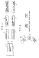
- FIG. 3 A first example of a conventional analog electric timepiece indicating forenoon/afternoon is shown in Figure 3.
- a motor 5 drives hour and minute (and second) hands 7, an AM/PM hand 8, which indicates forenoon/afternoon, and a date indicator or a day indicator 4, via respective gear trains 6, 61 and 62.
- the AM/PM hand 8 may be one that indicates the time on a twenty four hour scale.
- FIG. 4 is a block diagram of a second example of an analog electric timepiece that indicates forenoon/afternoon.
- a second motor (2) is additionally provided to drive the AM/PM hand 8, and is independently driven.
- the presence of the AM/PM hand 8 or the twenty four hour scale hand inevitably imposes limitations on the design, making it difficult to obtain a simple design like that of an ordinary analog timepiece.
- the AM/PM hand 8 and the other hands are mounted at the centre of a timepiece dial, furthermore, there may exist a total of four hands mounted at the centre, namely second hand, minute hand, hour hand and AM/PM hand 8.
- the axial height of the hands tends to increase, and it becomes difficult to read the time when the hands overlap one another.
- the hands have to be moved to appropriate positions, which takes twice as long as in an ordinary timepiece due to the presence of the AM/PM hand 8.
- the timepiece design may be made relatively simple when a twenty four hour scale hand is employed instead of the ordinary hour hand. However, for people who are accustomed to twelve hour analog timepieces, the twenty four hour analog timepiece is very inconvenient to read.
- an analog electric timepiece comprising a first motor for driving time indicating means by way of a first gear train, a second motor for driving day or date indicating means by way of a second gear train, and characterised by means for indicating forenoon and afternoon arranged to provide an indication in synchronism with an indication provided by the day or date indicating means.
- the date indicator or the day indicator bears letters or marks to indicate the forenoon and the afternoon.
- a date window or a day window is formed in a dial of the timepiece for displaying the day of the month or the day of the week inscribed on the date indicator or the day indicator and for indicating also the letters or marks representing the forenoon and the afternoon.
- letters or marks indicating the forenoon and the afternoon may be written on the dial near the date window or the day window.
- AM/PM window a window separately from the date window or the day window for indicating the forenoon/afternoon separately from the date or the day.
- an additional AM/PM indicator or AM/PM hand arranged to rotate together with the date indicator or the day indicator by way of an appropriate gear train.
- the AM/PM indicator in the form of a dial or the hand is coupled to a gear train of the same series as the gear train coupled to the date indicator or the day indicator so as to rotate in correspondence with the date indicator or the day indicator.
- the date indicator or the day indicator or the forenoon/afternoon indicator is conveniently driven by the second motor, which is controlled by an intregrated circuit.
- the integrated circuit there are preferably set in advance the number of steps of the motor per day calculated from the gear train ratio from the motor to the date indicator, day indicator or forenoon/afternoon indicator, and the number of steps for switching the forenoon into the afternoon calculated from markings on the forenoon/afternoon indicator for indicating the forenoon/afternoon.
- the motor is then controlled as required.
- the motor needs to generate a movement of ( m - n ) steps when the day changes from 11:59 PM midnight to 12:00 AM, and a movement of n steps when the time changes from 11:59 noon to 12.00 PM.
- the motor should generate a movement of (2 m - n ) steps when the day changes from the end of a month with thirty or less days (except February) into the first of the next month. Even when it is desired to indicate other time information (alarm time, time of other cities, etc) using the hour and minute (and second) hands, the motor should be controlled on the same basis.
- the invention may be applied to a timepiece without increasing the number of parts or imposing a limitation on design, and, further, without resulting in an increased amount of time being required for moving the hands of the timepiece when the mode is to be changed to display other time information.
- a first motor 5 drives hour and minute (and second) hands 7 via a first gear train 6, and a second (separate) motor 2 drives a date indicator or a day indicator 4 via a second gear train 3.
- An integrated circuit 1 drives the first motor 5 after every elapse of a pre-determined period to drive the hour and minute (and second) hands, and, at the same time, counts the hours, minutes and seconds.
- the following two methods have been proposed to bring the hours, minutes and seconds counted by the integrated circuit 1 and the positions of the hour and minute (and second) hands 7 into agreement with each other.
- a hand positioning condition (hereinafter referred to as 0 match mode) is set, the hands are set to pre-determined positions (e.g. the twelve o'clock position) by the user in the 0 match mode, and then the timepiece is used.
- the integrated circuit 1 must count the positions of the hour and minute (and second) hands at all times. That is, every time when the motor 5 is driven, the count is increased by +1 or -1 (when reversely rotated).
- means are provided to detect the positions of the hour and minute (and second) hands. That is, the positions of the hands are detected e.g. by optical sensors, magnetic sensors, or electric contacts.
- the forenoon/afternoon is to be indicated simply by the date indicator or the day indicator, the moment when the hour hand passes the twelve o'clock position needs simply to be detected.
- the present invention is not simply to indicate the forenoon/afternoon, but is to realise easily functions such as a twenty four hour scale, alarm and world times based upon the forenoon/afternoon indications.
- the positions of the hour and minute (and second) hands must be counted by the integrated circuit 1 during the period from one detection to the next, as in the method employing the 0 match mode, despite the provision of hand position detecting means.
- the integrated circuit 1 controls the second motor 2 to indicate the day of the month, the day of the week and the forenoon/afternoon.
- a 0 match mode or position detecting means in order to bring the contents of the day of the month, day of the week and forenoon/afternoon counted by the integrated circuit 1 into agreement with the position of the date indicator or the day indicator 4.
- Figure 1 shows the case of the 0 match mode.
- Figure 2 illustrates a second embodiment of the present invention.
- the first motor 5 drives the hour and minute (and second) hands 7 via a first gear train 6, and the second (separate) motor 2 drives an AM/PM dial or hand 8 via a second gear train 3 and further drives a date indicator or day indicator 4 via a third gear train 9.
- the integrated circuit 1 operates in the same manner as in the case of Figure 1.
- the AM/PM dial or AM/PM hand 8 may be freely arranged inside the timepiece.
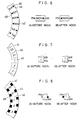
- FIG 5 shows a first example of a day indicator employed in the present invention.
- the day indicator 40 has an AM mark 44 and a PM mark 45 written in front of and behind the day 42 of the week.
- the day 42 and the AM mark 44 together are indicated through a day window as shown in Figure 5 (A).
- the time to be indicated is after noon, the day 42 and the PM mark 45 are indicated as shown in Figure 5 (B).
- FIG 6 shows a second example of a day indicator employed in the present invention.
- the day indicator 40 has an AM mark 44 and a PM mark 45 positioned to the right and the left sides of the day 42 of the week.
- the day 42 and the AM mark 44 indicating the letters AM are shown together in the day window as illustrated in Figure 6 (A).
- the PM mark 45 indicates the letters PM on the dial as shown in Figure 6 (B).
- Figure 7 shows a first example of a date indicator employed in the present invention.
- AM/PM marks 46 over and under the day 43 of the month.
- the day 43 and the AM/PM mark 46 are exposed together through the date window as shown in Figure 7 (A), the AM/PM mark 46 indicating the letters AM on the dial.
- the AM/PM mark 46 indicates the letters PM on the dial as shown in Figure 7 (B).
- Figure 8 shows a second example of a date indicator employed in the present invention.
- the date indicator 41 has an AM mark 44 and a PM mark 45 put to the upper right and the lower left of the day 43 of the month.
- the day 43 and the AM mark 44 are exposed through the date window as shown in Figure 8 (A).
- the PM mark 45 is exposed through the date window as shown in Figure 8 (B).
- Figure 9 is a plan view showing the coupling between the date indicator 4 and the separate motor 2 in the present invention.
- the date indicator or the day indicator 4 can be continuously rotated by the driving motor 2 via the second gear train 3, whereas the date indicator and the day indicator used for an ordinary analog timepiece are arranged to operate intermittently only once every day.
- the date indicator and the day indicator 4 move continuously in correspondence with the rotation of the driving motor 2.
- the number of steps ( n steps) for switching the forenoon to the afternoon should be determined depending upon the design of the AM/PM mark 46 and the like and of the date indicator or the day indicator.
- the date indicator or the day indicator 4 can also be rotated reversely.
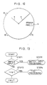
- FIG 10 is a block diagram illustrating the structure of the integrated circuit 1 of the timepiece according to the present invention.
- oscillation means 10 sends a reference signal to frequency dividing means 11, and timing signal generating means 12 generates timing signals for a variety of calculations and instruction executions upon receipt of output signal groups from said frequency dividing means 11.
- Signals from the timing signal generating means 12 are received by read only memory means 13 (hereinafter referred to as a ROM), in which the operating procedure has been programmed and are further received by calculation means 14 (hereinafter referred to as a CPU), which decodes instructions of the ROM and performs various computations and input/output operations.
- a data bus 19 random access memory means 15 (hereinafter referred to as a RAM), which stores time, date and hand position data, switch input means 18, and motor drive means 16 and 17.
- RAM random access memory means 15
- An output signal of the timing signal generating means 12 determines an address of the ROM 13 for supplying programming data to the CPU 14, which decodes the programming data that is sent thereto, processes the data stored in the RAM 15 and processes the data that is to be given to the motor drive means 16 and 17.
- the CPU 14 senses this input and performs the processing according to the operating procedure programmed in the ROM 13.
- Figure 11 is a block diagram showing the ROM 13 and the RAM 15 in detail.
- the forenoon/afternoon display by the date indicator or the day indicator is realised by programming forenoon -> afternoon processing means 131 and afternoon -> forenoon processing means 132 in the ROM 13.
- the ROM 13 consists of time counting processing means 130, the forenoon -> afternoon processing means 131, the afternoon -> forenoon processing means 132, time correcting processing means 133, date/day correcting processing means 134 and 0 match processing means 135.
- the forenoon/afternoon is displayed using the date indicator, and the hands consist of an hour and a minute hand, the minute hand being driven after every ten seconds.
- the RAM 15 consists of a portion 150 for storing the hand positions, a portion 151 for storing time data, a portion 152 for storing date or day indicator position, and a portion for storing the date or day.
- the hand position memory unit 150 consists of a hand position counter for counting the values 0 to 4319.
- the time data memory unit 151 consists of a one second counter for counting the values 0 to 9, a ten second counter for counting the values 0 to 5, a minute counter for counting the values 0 to 59, and an hour counter for counting the values 0 to 11.
- the forenoon/afternoon memory unit 152 consists of a forenoon/afternoon counter for counting the values 0 to 1.
- the date indicator position memory unit 153 consists of a date indicator position counter for counting the values 0 to ( m x 31) - 1.
- the date memory unit 154 consists of a date counter for counting the values 1 to 31. Since the time of twelve hours is counted with ten seconds as a unit, the counter needs to be capable of counting 12 x 3600 (seconds) / 10 (seconds) 4320. When the number of steps of the date indicator is m steps per day, the date indicator position counter needs to be capable of counting m x 31.
- Figure 12 shows the appearance of the timepiece according to the present invention, displaying the hour and minute hands 7 driven by the first motor, and the day 43 of the month and AM/PM mark 46 of the date indicator 4 through the date window.
- Switches A, B and K are used to correct the time and to effect 0 matching.
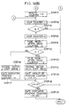
- FIG 13 is a flow chart representing a process start portion of the operation performed in the integrated circuit of the present invention. Under a halt condition, the integrated circuit 1 starts the program upon a switch input and a 1-Hz interrupt. In Figure 13, a judgement is made as to whether there is a switch input (step 1) or the 1-Hz interrupt (step 3) just after the program is started, the process branching to switch input processing (step 2) and to 1-Hz processing (step 4), respectively.
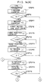
- FIGs 14 (A) and 14 (B) are flow charts representing the 1-Hz processing according to the present invention.
- this processing is executed in response to the 1-Hz interrupt.
- the one second counter in the RAM 15 is then increased by +1 (step 5), and the program branches to halt (step 6) when the count value of the one second counter is not 10.
- the counter is set to 0 (step 7) and the first motor is driven by one step (step 8) to advance the minute hand by ten seconds.
- the hand position counter is increased by +1 (step 9) and whether its count value is 4320 or not is checked (step 10).
- the hand position counter is set to 0 (step 11 ).
- the ten seconds counter, minute counter, hour counter and forenoon/afternoon counter are processed in the same manner (steps 12 to 23).
- the second motor is driven by ( m - n ) steps (step 24) and the date indicator position counter is increased by ( m - n ) (step 25).
- the second motor is driven by n steps (step 26), and the date indicator position counter is increased by n (step 27).
- Whether the date indicator position counter exceeds m x 31 or not is then checked (step 28).
- the date indicator position counter is decreased by ( m x 31) when the above value is exceeded (step 29).
- the foregoing describes the 1-Hz processing in an ordinary mode.
- the number m of steps of the date indicator per day and the number n of steps from the forenoon to the afternoon should be determined by the reduction ratio of the second gear train 3 and the design of the date indicator.
- FIGS 15 (A) and 15 (B) are flow charts representing switch input processing according to the present invention. This processing is executed in response to the switch input.
- the mode is divided into three, i.e. an ordinary mode, a time correction mode, and a 0 match mode (step 30).
- the switch exhibits no function and the process passes to halt.
- the program branches into four depending upon the switch that is depressed (step 31).
- the switch A When the switch A is depressed, the time is advanced by one minute and the program jumps to the step 14 of the 1-Hz processing.
- the switches A and K are simultaneously depressed, the time is advanced by one hour, and the program jumps to the step 18 of the 1-Hz processing.
- the switch B When the switch B is depressed, the date is advanced by one day and the program jumps to step 32, and when the switches B and K are simultaneously depressed, the date is advanced by seven days and the program jumps to step 34.
- the second motor is driven by required amounts respectively (steps 32, 34), and the date indicator position counter is increased by corresponding amounts (steps 33 and 35).
- step 36 Whether the date indicator position counter is in excess of m x 31 or not is next checked (step 36), and the date indicator position counter is increased by -( m x 31) (step 37) when the above value is exceeded.
- the program also branches into four depending upon the switch that is depressed (step 38).
- the switch A When the switch A is depressed, the hand is advanced by one step (corresponding to ten seconds) by driving the first motor by one step (step 39).
- step 39 The same processing is carried out when the switches A and K, B, and B and K are depressed (steps 40 to 42).
- the motors are only driven but the contents of the hand position counter and the date indicator position counter are not changed since this is the mode to bring the motor positions, hand positions of the RAM and the content of the date indicator position counter into agreement with one another, unlike the ordinary mode or the time correction mode.
- the date indicator or the day indicator is driven by a separate motor in order to display the forenoon/afternoon.
- the analog electronic timepiece displays the forenoon/afternoon without imposing the previous limitation on the design and, hence, easily realises the specifications that could not be realised so far due to such design limitation.
- the forenoon/afternoon display is suitable for timepieces having such specifications as alarm, world time, perpetual calendar, and the like.
Landscapes
- Physics & Mathematics (AREA)
- General Physics & Mathematics (AREA)
- Electromagnetism (AREA)
- Electromechanical Clocks (AREA)
Abstract

Description
- The present invention relates to an analog electric timepiece having a date indicator or a day indicator.
- A first example of a conventional analog electric timepiece indicating forenoon/afternoon is shown in Figure 3.
- A
motor 5 drives hour and minute (and second)hands 7, an AM/PM hand 8, which indicates forenoon/afternoon, and a date indicator or aday indicator 4, viarespective gear trains PM hand 8 may be one that indicates the time on a twenty four hour scale. - In an ordinary analog timepiece, it is also possible to change the gear train ratio of the hour hand to obtain a twenty four hour timepiece in order to indicate forenoon/afternoon.
- Figure 4 is a block diagram of a second example of an analog electric timepiece that indicates forenoon/afternoon. In this instance, a second motor (2) is additionally provided to drive the AM/
PM hand 8, and is independently driven. - In the case of these conventional timepieces, the presence of the AM/
PM hand 8 or the twenty four hour scale hand inevitably imposes limitations on the design, making it difficult to obtain a simple design like that of an ordinary analog timepiece. When the AM/PM hand 8 and the other hands are mounted at the centre of a timepiece dial, furthermore, there may exist a total of four hands mounted at the centre, namely second hand, minute hand, hour hand and AM/PM hand 8. Thus, the axial height of the hands tends to increase, and it becomes difficult to read the time when the hands overlap one another. - In the case of the first conventional timepiece, furthermore, when it is designed to indicate other time information (such as alarm time, times in other cities, etc) by a change of mode, the hands have to be moved to appropriate positions, which takes twice as long as in an ordinary timepiece due to the presence of the AM/
PM hand 8. - The timepiece design may be made relatively simple when a twenty four hour scale hand is employed instead of the ordinary hour hand. However, for people who are accustomed to twelve hour analog timepieces, the twenty four hour analog timepiece is very inconvenient to read.
- It is an object of the present invention to provide an analog electronic timepiece, which indicates the forenoon/afternoon but in which the above problems can be substantially avoided.
- According to the present invention, there is provided an analog electric timepiece comprising a first motor for driving time indicating means by way of a first gear train, a second motor for driving day or date indicating means by way of a second gear train, and characterised by means for indicating forenoon and afternoon arranged to provide an indication in synchronism with an indication provided by the day or date indicating means.
- In one embodiment of the present invention, the date indicator or the day indicator bears letters or marks to indicate the forenoon and the afternoon. A date window or a day window is formed in a dial of the timepiece for displaying the day of the month or the day of the week inscribed on the date indicator or the day indicator and for indicating also the letters or marks representing the forenoon and the afternoon. In addition, letters or marks indicating the forenoon and the afternoon may be written on the dial near the date window or the day window.
- Further, it is possible to provide a window (hereinafter referred to as an AM/PM window) separately from the date window or the day window for indicating the forenoon/afternoon separately from the date or the day.
- In another embodiment of the invention, there is provided an additional AM/PM indicator or AM/PM hand arranged to rotate together with the date indicator or the day indicator by way of an appropriate gear train. In this instance, the AM/PM indicator in the form of a dial or the hand, is coupled to a gear train of the same series as the gear train coupled to the date indicator or the day indicator so as to rotate in correspondence with the date indicator or the day indicator.
- The date indicator or the day indicator or the forenoon/afternoon indicator is conveniently driven by the second motor, which is controlled by an intregrated circuit. In the integrated circuit, there are preferably set in advance the number of steps of the motor per day calculated from the gear train ratio from the motor to the date indicator, day indicator or forenoon/afternoon indicator, and the number of steps for switching the forenoon into the afternoon calculated from markings on the forenoon/afternoon indicator for indicating the forenoon/afternoon. The motor is then controlled as required. For example, when the number of steps of the motor per day is m and the number of steps for switching the forenoon into the afternoon is n, the motor needs to generate a movement of (m - n) steps when the day changes from 11:59 PM midnight to 12:00 AM, and a movement of n steps when the time changes from 11:59 noon to 12.00 PM. In order to perform an automatic correction at the end of the month with the forenoon/afternoon indicated on a date indicator, the motor should generate a movement of (2m - n) steps when the day changes from the end of a month with thirty or less days (except February) into the first of the next month. Even when it is desired to indicate other time information (alarm time, time of other cities, etc) using the hour and minute (and second) hands, the motor should be controlled on the same basis.
- As described below, the invention may be applied to a timepiece without increasing the number of parts or imposing a limitation on design, and, further, without resulting in an increased amount of time being required for moving the hands of the timepiece when the mode is to be changed to display other time information.
- The invention is described further, by way of example, with reference to the accompanying drawings, in which:-
- Figure 1 is a block diagram illustrating a first embodiment of an analog electronic timepiece according to the present invention;
- Figure 2 is a block diagram illustrating a second embodiment of an analog electronic timepiece according to the present invention;
- Figure 3 is a block diagram illustrating a first example of a conventional timepiece;
- Figure 4 is a block diagram illustrating a second example of a conventional timepiece;
- Figure 5 is a diagram illustrating a first example of day indicator for application in the present invention;
- Figure 6 is a diagram illustrating a second example of day indicator for application in the present invention;
- Figure 7 is a diagram illustrating a first example of date indicator for application in the present invention;
- Figure 8 is a diagram illustrating a second example of date indicator for application in the present invention;
- Figure 9 is a plan view showing the coupling between the date indicator and an associated motor of the timepiece according to the present invention;
- Figure 10 is a block diagram showing the structure of an integrated circuit of the timepiece according to the present invention;
- Figure 11 is a block diagram illustrating details of a ROM and a RAM of the integrated circuit of Figure 10;
- Figure 12 shows the appearance of the timepiece according to the present invention;
- Figure 13 is a flow chart representing a process start portion of the operation of the integrated circuit of Figure 10;
- Figures 14 (A) and 14 (B) are flow charts representing 1-Hz processing in the integrated circuit of Figure 10; and
- Figures 15 (A) and 15 (B) are flow charts representing switch input processing in the integrated circuit of Figure 10.
- Referring initially to Figure 1, a
first motor 5 drives hour and minute (and second)hands 7 via afirst gear train 6, and a second (separate)motor 2 drives a date indicator or aday indicator 4 via asecond gear train 3. An integratedcircuit 1 drives thefirst motor 5 after every elapse of a pre-determined period to drive the hour and minute (and second) hands, and, at the same time, counts the hours, minutes and seconds. The following two methods have been proposed to bring the hours, minutes and seconds counted by the integratedcircuit 1 and the positions of the hour and minute (and second)hands 7 into agreement with each other. - According to one method, a hand positioning condition (hereinafter referred to as 0 match mode) is set, the hands are set to pre-determined positions (e.g. the twelve o'clock position) by the user in the 0 match mode, and then the timepiece is used. In the case of this method, the integrated
circuit 1 must count the positions of the hour and minute (and second) hands at all times. That is, every time when themotor 5 is driven, the count is increased by +1 or -1 (when reversely rotated). - According to the other method, means are provided to detect the positions of the hour and minute (and second) hands. That is, the positions of the hands are detected e.g. by optical sensors, magnetic sensors, or electric contacts. When the forenoon/afternoon is to be indicated simply by the date indicator or the day indicator, the moment when the hour hand passes the twelve o'clock position needs simply to be detected.
- However, the present invention is not simply to indicate the forenoon/afternoon, but is to realise easily functions such as a twenty four hour scale, alarm and world times based upon the forenoon/afternoon indications. In order to realise these functions, the positions of the hour and minute (and second) hands must be counted by the integrated
circuit 1 during the period from one detection to the next, as in the method employing the 0 match mode, despite the provision of hand position detecting means. - Depending upon the value it has counted, the integrated
circuit 1 controls thesecond motor 2 to indicate the day of the month, the day of the week and the forenoon/afternoon. Just like the case of the hour and minute (and second)hands 7 mentioned above, there must be provided a 0 match mode or position detecting means, in order to bring the contents of the day of the month, day of the week and forenoon/afternoon counted by the integratedcircuit 1 into agreement with the position of the date indicator or theday indicator 4. Figure 1 shows the case of the 0 match mode. - Figure 2 illustrates a second embodiment of the present invention. As in the Figure 1 embodiment, the
first motor 5 drives the hour and minute (and second)hands 7 via afirst gear train 6, and the second (separate)motor 2 drives an AM/PM dial orhand 8 via asecond gear train 3 and further drives a date indicator orday indicator 4 via athird gear train 9. Theintegrated circuit 1 operates in the same manner as in the case of Figure 1. In this embodiment of the present invention, the AM/PM dial or AM/PM hand 8 may be freely arranged inside the timepiece. - Figure 5 shows a first example of a day indicator employed in the present invention. The
day indicator 40 has anAM mark 44 and aPM mark 45 written in front of and behind theday 42 of the week. When the time to be indicated is before noon, theday 42 and theAM mark 44 together are indicated through a day window as shown in Figure 5 (A). When the time to be indicated is after noon, theday 42 and thePM mark 45 are indicated as shown in Figure 5 (B). - Figure 6 shows a second example of a day indicator employed in the present invention. The
day indicator 40 has anAM mark 44 and aPM mark 45 positioned to the right and the left sides of theday 42 of the week. When the time to be indicated is before noon, theday 42 and theAM mark 44 indicating the letters AM are shown together in the day window as illustrated in Figure 6 (A). When the time to be indicated is after noon, thePM mark 45 indicates the letters PM on the dial as shown in Figure 6 (B). - Figure 7 shows a first example of a date indicator employed in the present invention. On the
date indicator 41 are placed AM/PM marks 46 over and under theday 43 of the month. When the time to be indicated is before noon, theday 43 and the AM/PM mark 46 are exposed together through the date window as shown in Figure 7 (A), the AM/PM mark 46 indicating the letters AM on the dial. When the time to be indicated is after noon, the AM/PM mark 46 indicates the letters PM on the dial as shown in Figure 7 (B). - Figure 8 shows a second example of a date indicator employed in the present invention. The
date indicator 41 has anAM mark 44 and aPM mark 45 put to the upper right and the lower left of theday 43 of the month. When the time to be indicated is before noon, theday 43 and theAM mark 44 are exposed through the date window as shown in Figure 8 (A). When the time to be indicated is after noon, thePM mark 45 is exposed through the date window as shown in Figure 8 (B). - Figure 9 is a plan view showing the coupling between the
date indicator 4 and theseparate motor 2 in the present invention. The date indicator or theday indicator 4 can be continuously rotated by the drivingmotor 2 via thesecond gear train 3, whereas the date indicator and the day indicator used for an ordinary analog timepiece are arranged to operate intermittently only once every day. In the present invention employing the mechanism shown in Figure 9, however, the date indicator and theday indicator 4 move continuously in correspondence with the rotation of the drivingmotor 2. For instance, if thesecond gear chain 3 is set to a reduction ratio whereby it takes rotation of theseparate motor 2 by an amount of fifty steps (m = 50) in order to turn the date indicator by an amount of one day (1/31 of a turn), it is made possible to control the date indicator with a precision of 360° - 31 = 0.13°. The number of steps (n steps) for switching the forenoon to the afternoon should be determined depending upon the design of the AM/PM mark 46 and the like and of the date indicator or the day indicator. - By reversely rotating the driving
motor 2, furthermore, the date indicator or theday indicator 4 can also be rotated reversely. - Figure 10 is a block diagram illustrating the structure of the
integrated circuit 1 of the timepiece according to the present invention. In Figure 10, oscillation means 10 sends a reference signal to frequency dividing means 11, and timing signal generating means 12 generates timing signals for a variety of calculations and instruction executions upon receipt of output signal groups from said frequency dividing means 11. Signals from the timing signal generating means 12 are received by read only memory means 13 (hereinafter referred to as a ROM), in which the operating procedure has been programmed and are further received by calculation means 14 (hereinafter referred to as a CPU), which decodes instructions of the ROM and performs various computations and input/output operations. To theCPU 14 are connected, via adata bus 19, random access memory means 15 (hereinafter referred to as a RAM), which stores time, date and hand position data, switch input means 18, and motor drive means 16 and 17. - Operation of the system will now be described with reference to Figure 10. An output signal of the timing signal generating means 12 determines an address of the
ROM 13 for supplying programming data to theCPU 14, which decodes the programming data that is sent thereto, processes the data stored in theRAM 15 and processes the data that is to be given to the motor drive means 16 and 17. When an input is received from switch input means 18, theCPU 14 senses this input and performs the processing according to the operating procedure programmed in theROM 13. - Figure 11 is a block diagram showing the
ROM 13 and theRAM 15 in detail. According to the present invention, the forenoon/afternoon display by the date indicator or the day indicator is realised by programming forenoon -> afternoon processing means 131 and afternoon -> forenoon processing means 132 in theROM 13. - The
ROM 13 consists of time counting processing means 130, the forenoon -> afternoon processing means 131, the afternoon -> forenoon processing means 132, time correcting processing means 133, date/day correcting processing means 134 and 0 match processing means 135. - In this case, the forenoon/afternoon is displayed using the date indicator, and the hands consist of an hour and a minute hand, the minute hand being driven after every ten seconds. The
RAM 15 consists of aportion 150 for storing the hand positions, aportion 151 for storing time data, aportion 152 for storing date or day indicator position, and a portion for storing the date or day. The handposition memory unit 150 consists of a hand position counter for counting thevalues 0 to 4319. The timedata memory unit 151 consists of a one second counter for counting thevalues 0 to 9, a ten second counter for counting thevalues 0 to 5, a minute counter for counting thevalues 0 to 59, and an hour counter for counting thevalues 0 to 11. The forenoon/afternoon memory unit 152 consists of a forenoon/afternoon counter for counting thevalues 0 to 1. The date indicatorposition memory unit 153 consists of a date indicator position counter for counting thevalues 0 to (m x 31) - 1. Thedate memory unit 154 consists of a date counter for counting thevalues 1 to 31. Since the time of twelve hours is counted with ten seconds as a unit, the counter needs to be capable of counting 12 x 3600 (seconds) / 10 (seconds) 4320. When the number of steps of the date indicator is m steps per day, the date indicator position counter needs to be capable of counting m x 31. - Figure 12 shows the appearance of the timepiece according to the present invention, displaying the hour and
minute hands 7 driven by the first motor, and theday 43 of the month and AM/PM mark 46 of thedate indicator 4 through the date window. Switches A, B and K are used to correct the time and to effect 0 matching. - Figure 13 is a flow chart representing a process start portion of the operation performed in the integrated circuit of the present invention. Under a halt condition, the
integrated circuit 1 starts the program upon a switch input and a 1-Hz interrupt. In Figure 13, a judgement is made as to whether there is a switch input (step 1) or the 1-Hz interrupt (step 3) just after the program is started, the process branching to switch input processing (step 2) and to 1-Hz processing (step 4), respectively. - Figures 14 (A) and 14 (B) are flow charts representing the 1-Hz processing according to the present invention. In an ordinary mode, this processing is executed in response to the 1-Hz interrupt. The one second counter in the
RAM 15 is then increased by +1 (step 5), and the program branches to halt (step 6) when the count value of the one second counter is not 10. When the count value of the one second counter is 10, the counter is set to 0 (step 7) and the first motor is driven by one step (step 8) to advance the minute hand by ten seconds. At the same time, the hand position counter is increased by +1 (step 9) and whether its count value is 4320 or not is checked (step 10). When the count value is 4320, the hand position counter is set to 0 (step 11 ). Thereafter, the ten seconds counter, minute counter, hour counter and forenoon/afternoon counter are processed in the same manner (steps 12 to 23). When the day changes from 11:59 PM midnight to 12.00 AM, the second motor is driven by (m - n) steps (step 24) and the date indicator position counter is increased by (m - n) (step 25). When the time changes from 11:59 AM noon to 12:00 PM, the second motor is driven by n steps (step 26), and the date indicator position counter is increased by n (step 27). Whether the date indicator position counter exceeds m x 31 or not is then checked (step 28). The date indicator position counter is decreased by (m x 31) when the above value is exceeded (step 29). - The foregoing describes the 1-Hz processing in an ordinary mode. The number m of steps of the date indicator per day and the number n of steps from the forenoon to the afternoon should be determined by the reduction ratio of the
second gear train 3 and the design of the date indicator. - Figures 15 (A) and 15 (B) are flow charts representing switch input processing according to the present invention. This processing is executed in response to the switch input. First, the mode is divided into three, i.e. an ordinary mode, a time correction mode, and a 0 match mode (step 30). In the ordinary mode the switch exhibits no function and the process passes to halt.
- When it is the time correction mode, the program branches into four depending upon the switch that is depressed (step 31). When the switch A is depressed, the time is advanced by one minute and the program jumps to the
step 14 of the 1-Hz processing. When the switches A and K are simultaneously depressed, the time is advanced by one hour, and the program jumps to thestep 18 of the 1-Hz processing. When the switch B is depressed, the date is advanced by one day and the program jumps to step 32, and when the switches B and K are simultaneously depressed, the date is advanced by seven days and the program jumps to step 34. The second motor is driven by required amounts respectively (steps 32, 34), and the date indicator position counter is increased by corresponding amounts (steps 33 and 35). Whether the date indicator position counter is in excess of m x 31 or not is next checked (step 36), and the date indicator position counter is increased by -(m x 31) (step 37) when the above value is exceeded. In the case of the 0 match mode, the program also branches into four depending upon the switch that is depressed (step 38). When the switch A is depressed, the hand is advanced by one step (corresponding to ten seconds) by driving the first motor by one step (step 39). The same processing is carried out when the switches A and K, B, and B and K are depressed (steps 40 to 42). In the case of the 0 match mode, the motors are only driven but the contents of the hand position counter and the date indicator position counter are not changed since this is the mode to bring the motor positions, hand positions of the RAM and the content of the date indicator position counter into agreement with one another, unlike the ordinary mode or the time correction mode. - According to the analog electronic timepiece of the present invention, the date indicator or the day indicator is driven by a separate motor in order to display the forenoon/afternoon. The analog electronic timepiece displays the forenoon/afternoon without imposing the previous limitation on the design and, hence, easily realises the specifications that could not be realised so far due to such design limitation. For example, the forenoon/afternoon display is suitable for timepieces having such specifications as alarm, world time, perpetual calendar, and the like.
Claims (9)
Applications Claiming Priority (2)
| Application Number | Priority Date | Filing Date | Title |
|---|---|---|---|
| JP231841/89 | 1989-09-01 | ||
| JP23184189A JPH0390888A (en) | 1989-09-01 | 1989-09-01 | Analog electronic watch |
Publications (2)
| Publication Number | Publication Date |
|---|---|
| EP0415734A2 true EP0415734A2 (en) | 1991-03-06 |
| EP0415734A3 EP0415734A3 (en) | 1991-09-25 |
Family
ID=16929851
Family Applications (1)
| Application Number | Title | Priority Date | Filing Date |
|---|---|---|---|
| EP19900309434 Withdrawn EP0415734A3 (en) | 1989-09-01 | 1990-08-29 | Analog electric timepiece |
Country Status (2)
| Country | Link |
|---|---|
| EP (1) | EP0415734A3 (en) |
| JP (1) | JPH0390888A (en) |
Cited By (6)
| Publication number | Priority date | Publication date | Assignee | Title |
|---|---|---|---|---|
| EP0744675A1 (en) * | 1995-05-24 | 1996-11-27 | Montres Rolex Sa | Time measuring instrument particularly electric wrist watch of the analogue type |
| WO2007031347A1 (en) | 2005-09-13 | 2007-03-22 | Tag Heuer Sa | Watch component for displaying indicia in a window |
| DE19882138B4 (en) * | 1997-12-26 | 2007-05-16 | Citizen Watch Co Ltd | Electronic clock with calendar device |
| WO2008151458A1 (en) * | 2007-06-15 | 2008-12-18 | Isa Swiss S.A. | Digital display method for an analogue watch and analogue watch using this method |
| CH703542B1 (en) * | 2007-06-15 | 2012-02-15 | Isa Swiss Sa | Time relative data e.g. date, displaying method for analog watch, involves making display to be contrast with background, and reversing contrast at midday and midnight by actuating contacts to differentiate morning from afternoon |
| RU2525465C1 (en) * | 2013-06-14 | 2014-08-20 | Общество с ограниченной ответственностью "Константин Чайкин" | Positional indication apparatus for clock and clock having positional indication apparatus |
Citations (2)
| Publication number | Priority date | Publication date | Assignee | Title |
|---|---|---|---|---|
| JPS5599090A (en) * | 1979-01-23 | 1980-07-28 | Seiko Instr & Electronics Ltd | Analog alarm watch |
| EP0247418A1 (en) * | 1986-05-26 | 1987-12-02 | Eta SA Fabriques d'Ebauches | Perpetual calender clock with two motors |
Family Cites Families (2)
| Publication number | Priority date | Publication date | Assignee | Title |
|---|---|---|---|---|
| JPS53107872A (en) * | 1977-03-03 | 1978-09-20 | Kaname Aoki | Time dependentttype display device |
| CH661833GA3 (en) * | 1985-12-18 | 1987-08-31 |
-
1989
- 1989-09-01 JP JP23184189A patent/JPH0390888A/en active Pending
-
1990
- 1990-08-29 EP EP19900309434 patent/EP0415734A3/en not_active Withdrawn
Patent Citations (2)
| Publication number | Priority date | Publication date | Assignee | Title |
|---|---|---|---|---|
| JPS5599090A (en) * | 1979-01-23 | 1980-07-28 | Seiko Instr & Electronics Ltd | Analog alarm watch |
| EP0247418A1 (en) * | 1986-05-26 | 1987-12-02 | Eta SA Fabriques d'Ebauches | Perpetual calender clock with two motors |
Non-Patent Citations (2)
| Title |
|---|
| BULLETIN ANNUEL DE LA SOC. SUISSE DE CHRONOMETRIE, vol. 11, no. 1, 1982, pages 77-81, Neuchatel, CH; R. BESSON: "Montre reveil à quartz et à affichage à aiguilles" * |
| PATENT ABSTRACTS OF JAPAN, vol. 4, no. 149 (P-32), 21st October 1980; & JP-A-55 99 090 (SEIKO INSTR. & ELECTRONICS LTD) 28-07-1980 * |
Cited By (12)
| Publication number | Priority date | Publication date | Assignee | Title |
|---|---|---|---|---|
| EP0744675A1 (en) * | 1995-05-24 | 1996-11-27 | Montres Rolex Sa | Time measuring instrument particularly electric wrist watch of the analogue type |
| CH687727GA3 (en) * | 1995-05-24 | 1997-02-14 | Rolex Montres | Time instrument including an electric wristwatch of the analog type. |
| US5790478A (en) * | 1995-05-24 | 1998-08-04 | Montres Rolex S.A. | Time-keeping instrument, in particular an analog-type electric wrist watch |
| DE19882138B4 (en) * | 1997-12-26 | 2007-05-16 | Citizen Watch Co Ltd | Electronic clock with calendar device |
| WO2007031347A1 (en) | 2005-09-13 | 2007-03-22 | Tag Heuer Sa | Watch component for displaying indicia in a window |
| US7889602B2 (en) | 2005-09-13 | 2011-02-15 | Lvmh Swiss Manufactures Sa | Watch with a multifunctional display |
| CN101263436B (en) * | 2005-09-13 | 2011-04-13 | Lvmh瑞士制造业股份公司 | Watch with multipurpose display |
| CN101263435B (en) * | 2005-09-13 | 2012-09-05 | Lvmh瑞士制造业股份公司 | Watch component for displaying indicia in a window |
| KR101304957B1 (en) * | 2005-09-13 | 2013-09-06 | 엘브이엠에이치 스위스 매뉴팩츄어스 에스에이 | Watch component for displaying indicia in a window |
| WO2008151458A1 (en) * | 2007-06-15 | 2008-12-18 | Isa Swiss S.A. | Digital display method for an analogue watch and analogue watch using this method |
| CH703542B1 (en) * | 2007-06-15 | 2012-02-15 | Isa Swiss Sa | Time relative data e.g. date, displaying method for analog watch, involves making display to be contrast with background, and reversing contrast at midday and midnight by actuating contacts to differentiate morning from afternoon |
| RU2525465C1 (en) * | 2013-06-14 | 2014-08-20 | Общество с ограниченной ответственностью "Константин Чайкин" | Positional indication apparatus for clock and clock having positional indication apparatus |
Also Published As
| Publication number | Publication date |
|---|---|
| JPH0390888A (en) | 1991-04-16 |
| EP0415734A3 (en) | 1991-09-25 |
Similar Documents
| Publication | Publication Date | Title |
|---|---|---|
| US20130322218A1 (en) | World Time Timepiece | |
| EP0488249B1 (en) | Analog electronic timepiece having an electric-optical display device | |
| WO2009112111A1 (en) | Indicator assembly for a wearable electronic device | |
| US7120091B1 (en) | Electronic device with calendar function | |
| US5668781A (en) | Analog electronic timepiece having a multifunctional calendar disc | |
| US4726687A (en) | Analog timepiece with device for electronic data input | |
| US20050122845A1 (en) | Wearable electronic device with mode operation indicator | |
| JP2000065958A (en) | Astronomical watch | |
| US5469410A (en) | Watch with date dial | |
| EP0347249A2 (en) | An IC chip for an analog electronic watch | |
| EP0652498B1 (en) | Electronic watch having multi-functional display | |
| US7423936B2 (en) | Electronic device with scheduled occurrence indicators | |
| EP0415734A2 (en) | Analog electric timepiece | |
| US5239522A (en) | Method for the setting of the perpetual calendar of an analogic quartz chronograph as well as a quartz chronograph for carrying it out | |
| US20090040879A1 (en) | Wearable electronic device with multiple display functionality | |
| EP0347251A2 (en) | A multi-functional analog electronic watch | |
| JP6512203B2 (en) | Analog display device, electronic watch, display operation control method, and program | |
| US5095469A (en) | Electronic watch with analog time display | |
| GB2046960A (en) | Analogue alarm electronic timepiece | |
| JP6495999B2 (en) | A watch with a calendar display mechanism | |
| JP3063171B2 (en) | Electronic clock | |
| JP3157219B2 (en) | Pointer-type multifunction clock | |
| US4280207A (en) | Electronic timepiece and digital display therefor | |
| JP2606010Y2 (en) | Multifunction electronic clock | |
| GB2052115A (en) | Electronic timepiece with auxiliary digital display |
Legal Events
| Date | Code | Title | Description |
|---|---|---|---|
| PUAI | Public reference made under article 153(3) epc to a published international application that has entered the european phase |
Free format text: ORIGINAL CODE: 0009012 |
|
| AK | Designated contracting states |
Kind code of ref document: A2 Designated state(s): CH DE FR GB LI |
|
| PUAL | Search report despatched |
Free format text: ORIGINAL CODE: 0009013 |
|
| AK | Designated contracting states |
Kind code of ref document: A3 Designated state(s): CH DE FR GB LI |
|
| 17P | Request for examination filed |
Effective date: 19920212 |
|
| 17Q | First examination report despatched |
Effective date: 19930331 |
|
| STAA | Information on the status of an ep patent application or granted ep patent |
Free format text: STATUS: THE APPLICATION IS DEEMED TO BE WITHDRAWN |
|
| 18D | Application deemed to be withdrawn |
Effective date: 19930811 |