EP0415563B1 - Floor scrubber having laterally variable scrub brush position - Google Patents
Floor scrubber having laterally variable scrub brush position Download PDFInfo
- Publication number
- EP0415563B1 EP0415563B1 EP90308378A EP90308378A EP0415563B1 EP 0415563 B1 EP0415563 B1 EP 0415563B1 EP 90308378 A EP90308378 A EP 90308378A EP 90308378 A EP90308378 A EP 90308378A EP 0415563 B1 EP0415563 B1 EP 0415563B1
- Authority
- EP
- European Patent Office
- Prior art keywords
- scrub head
- floor
- frame
- scrub
- machine
- Prior art date
- Legal status (The legal status is an assumption and is not a legal conclusion. Google has not performed a legal analysis and makes no representation as to the accuracy of the status listed.)
- Expired - Lifetime
Links
- 238000005201 scrubbing Methods 0.000 claims description 27
- 230000005484 gravity Effects 0.000 claims description 15
- 238000000034 method Methods 0.000 claims description 4
- 239000007787 solid Substances 0.000 claims description 2
- 238000006073 displacement reaction Methods 0.000 claims 1
- XLYOFNOQVPJJNP-UHFFFAOYSA-N water Substances O XLYOFNOQVPJJNP-UHFFFAOYSA-N 0.000 description 10
- 230000007246 mechanism Effects 0.000 description 3
- 230000009467 reduction Effects 0.000 description 3
- 230000009471 action Effects 0.000 description 2
- 230000007423 decrease Effects 0.000 description 2
- 229910000831 Steel Inorganic materials 0.000 description 1
- 230000004075 alteration Effects 0.000 description 1
- 230000008859 change Effects 0.000 description 1
- 230000008878 coupling Effects 0.000 description 1
- 238000010168 coupling process Methods 0.000 description 1
- 238000005859 coupling reaction Methods 0.000 description 1
- 238000010586 diagram Methods 0.000 description 1
- 230000004048 modification Effects 0.000 description 1
- 238000012986 modification Methods 0.000 description 1
- 230000000717 retained effect Effects 0.000 description 1
- 238000005096 rolling process Methods 0.000 description 1
- 230000007480 spreading Effects 0.000 description 1
- 239000010959 steel Substances 0.000 description 1
- 238000006467 substitution reaction Methods 0.000 description 1
- 239000000725 suspension Substances 0.000 description 1
Images


Classifications
-
- A—HUMAN NECESSITIES
- A47—FURNITURE; DOMESTIC ARTICLES OR APPLIANCES; COFFEE MILLS; SPICE MILLS; SUCTION CLEANERS IN GENERAL
- A47L—DOMESTIC WASHING OR CLEANING; SUCTION CLEANERS IN GENERAL
- A47L11/00—Machines for cleaning floors, carpets, furniture, walls, or wall coverings
- A47L11/40—Parts or details of machines not provided for in groups A47L11/02 - A47L11/38, or not restricted to one of these groups, e.g. handles, arrangements of switches, skirts, buffers, levers
- A47L11/4052—Movement of the tools or the like perpendicular to the cleaning surface
- A47L11/4055—Movement of the tools or the like perpendicular to the cleaning surface for lifting the tools to a non-working position
-
- A—HUMAN NECESSITIES
- A47—FURNITURE; DOMESTIC ARTICLES OR APPLIANCES; COFFEE MILLS; SPICE MILLS; SUCTION CLEANERS IN GENERAL
- A47L—DOMESTIC WASHING OR CLEANING; SUCTION CLEANERS IN GENERAL
- A47L11/00—Machines for cleaning floors, carpets, furniture, walls, or wall coverings
- A47L11/29—Floor-scrubbing machines characterised by means for taking-up dirty liquid
- A47L11/292—Floor-scrubbing machines characterised by means for taking-up dirty liquid having rotary tools
- A47L11/293—Floor-scrubbing machines characterised by means for taking-up dirty liquid having rotary tools the tools being disc brushes
-
- A—HUMAN NECESSITIES
- A47—FURNITURE; DOMESTIC ARTICLES OR APPLIANCES; COFFEE MILLS; SPICE MILLS; SUCTION CLEANERS IN GENERAL
- A47L—DOMESTIC WASHING OR CLEANING; SUCTION CLEANERS IN GENERAL
- A47L11/00—Machines for cleaning floors, carpets, furniture, walls, or wall coverings
- A47L11/40—Parts or details of machines not provided for in groups A47L11/02 - A47L11/38, or not restricted to one of these groups, e.g. handles, arrangements of switches, skirts, buffers, levers
- A47L11/4061—Steering means; Means for avoiding obstacles; Details related to the place where the driver is accommodated
Definitions
- a scrub head In the design of industrial floor scrubbing machines it is common to mount the scrub brushes and their drive motors in a housing called a scrub head.
- This scrub head is commonly attached in some articulated manner to the frame of the machine so that the brushes can be raised for transport and lowered to the floor for working, and when working will bear against the floor even though it may undulate somewhat.
- the scrub head is variously mounted in front of, underneath amidships, or behind the machine frame, and a suction pickup squeegee is universally used to pick up the soiled scrub water.
- the scrub head and the squeegee are commonly within the width of the machine frame, for they are vulnerable to being damaged by collision with fixed objects if they extend much wider than the frame.
- a scrub brush within a machine frame width cannot scrub closely along a wall, however, because of the surrounding machine structure. So a scrubbing side brush is often provided at a front corner of the machine, extending out forwardly and laterally beyond the machine frame, to scrub along walls. Side brushes, however, are quite vulnerable to being damaged by collisions with fixed objects, and their scrubbing pattern on the floor often does not match the pattern of the main brushes. In sharp turns a side brush, because of its forward location, may track outside of the pickup squeegee and consequently leave a trail of water on the floor which has otherwise been damp dried by the squeegee.
- US-A-4 757 566 discloses a floor scrubber which has a system for controlling the torque applied to its scrub brush by sensing the current in the brush drive motor and raising or lowering the scrub head containing the brush against the floor being scrubbed to maintain constant torque in the brush. There is no provision for lateral movement of the scrub head, and hence the problem is not addressed of applying a vertical down force to it without affecting the direction, amplitude or point on the scrub head for applying the down force in a situation where the scrub head is moved laterally.
- US-A-4 506 405 discloses a floor scrubber in which pneumatic means are provided for lifting the scrub brushes or for applying controllable amounts of down pressure to them.
- the scrub head in this scrubber is not laterally movable, and so this patent likewise does not address the problem of controlling the amplitude, direction and point of application of a down force applied to a scrub head that can be moved laterally.
- US-A-3 702 488 discloses a floor scrubber with a scrub head attached by linkages to a prime mover.
- a single-acting hydraulic cylinder lifts the scrub head, either completely for transport, or partially to support part of its weight during scrubbing.
- the only down force that can be applied to the scrub head is the force of gravity due to all or part of the weight of the scrub head, which would appear to be very heavy. In other words, there is no provision for a positive down force in addition to the weight of the scrub head.
- a primary aim of the present invention - in the light of the prior art discussed above - is to provide an industrial floor scrubber without a scrubbing side brush and with a vertical force other than gravity applied to its main scrubbing brushes, which can scrub closely along a wall like a scrubber equipped with a scrubbing side brush, thereby eliminating the shortcomings of a side brush while retaining its useful function.
- Another aim is to provide a scrubber having a scrub head containing scrub brushes which, on occasion, can be extended laterally outside the frame of the scrubber to scrub closely along a wall or can be operated in a normal position under the scrubber for minimum machine width.
- Another aim is to provide a resilient coupling between the scrub head and the means for extending it laterally so that it can automatically retract in event of striking a solid obstacle and automatically extend again after passing the obstacle.
- Another aim is to provide means for applying a vertical force other than gravity to the scrub head which will be unchanged in direction or magnitude by moving the scrub head from a normal position under the scrubber to a laterally extended position or vice versa.
- Another aim is to assure uniform contact pressure of the scrub brushes against the floor in both normal and extended positions of the scrub head by locating the vertical force on the scrub head, the center of gravity of the scrub head, and the center of the contact area of the scrub brushes with the floor in one vertical line.
- a preferred embodiment of the invention is a battery powered industrial scrubber on which the operator rides. It is a tricycle vehicle, with a single steerable, powered wheel in front and two free rolling wheels in the rear. With a scrub head mounted amidships such a vehicle can readily be steered close to a wall, scrub along it, and be steered away from it at will.
- the scrubber has a scrub head assembly which carries two disc type scrub brushes and their two electric drive motors with reduction gear boxes, but there is nothing in the invention which limits the number or type of brushes, or the type of drives used.
- the scrub head is also provided with means for dispensing scrub water, and suitable skirting for water control.
- the scrub head assembly is attached to the scrubber frame with two parallel ball jointed links on each side, which pull it along. These links allow it to be lifted for transport or lowered to the floor for working, and to follow an uneven floor. They also allow it to move from side to side. This latter capability is utilized by mounting a linear electric actuator or the like crosswise under the machine frame and connecting it to the scrub head. The actuator may be retracted or extended.
- the scrub head When in retracted position it locates the scrub head under the machine frame, which is its normal position, for best protection against damage and best relationship to the squeegee. However, by extending the actuator the scrub head may be moved laterally, extending it, say, about five inches beyond the side of the machine frame. When thus extended, the main scrub brush on the extended side can scrub as close to a wall as a side brush could, so no scrubbing side brush is needed.
- the actuator is resiliently coupled to the scrub head through a gas spring which is normally extended.
- the outer end of the scrub head has an angled bumper plate on it, so that if the protruding scrub head strikes an obstacle it will be deflected off and pushed back under the machine, compressing the gas spring, and thus will generally avoid being damaged. It swings in or out easily because, as mentioned before, it is attached to the frame with ball jointed links. After passing the obstacle the gas spring will automatically extend and push the scrub head out again.
- a second electric actuator or the like mounted longitudinally on the underside of the scrubber frame and connected through a spring loaded bell crank and a linkage to the scrub head to raise it for transport and lower it to the floor for work.
- This system can be and preferably is made capable of exerting a variable vertical force on the scrub head which will increase or decrease the pressure of the brushes against the floor.
- This pressure may be and preferably is automatically controlled as described in US-A-4 757 566 which varies the vertical force on a scrub head to control the torque developed in the brushes of a scrubber.
- the load current in one or both of the brush motors, which will vary as the brush torque, is sensed to provide the necessary control feedback. Some other mode of control may be used if preferred; the invention does not limit this. In any case the actuator will extend or retract and thus apply more or less vertical force on the scrub head.
- the actuator is connected through its bell crank to the scrub head in such a way that the upward or downward force on the scrub head will be vertical whether the scrub head is in its normal position under the frame or extended out. This is accomplished by connecting the actuator bell crank to the scrub head with a four bar linkage that gives a straight line lateral motion of a movable member.
- a four bar linkage that gives a straight line lateral motion of a movable member.
- Tchebicheff's linkage One that was found to be suitable is known as Tchebicheff's linkage.
- the invention is directed at the problem of building an improved industrial floor scrubber with the capability of scrubbing closely along a wall without a scrubbing side brush to avoid the problems inherent with side brushes, and having vertical force in addition to gravity applied to its scrub head, for example as taught in US-A-4 757 566.
- the main brushes are built into a scrub head which can have a vertical force applied to it and which can be operated on occasion in a position where the brushes are extended laterally beyond the side of the frame and thus can scrub along a wall in the same manner as a side brush.
- the mechanism which provides vertical force on the scrub head is connected to the scrub head in such a way that it will apply vertical force whether the brush head is in normal position or extended.
- a four bar linkage attributed to Tchebicheff meets this requirement. Other linkages or mechanisms will perform this function also.
- the elements of the scrub head assembly which contribute to its weight are disposed in such a way that the center of gravity of the scrub head is in a vertical line-with the center of the contact area of the scrub brushes with the floor.
- the linkage which applies vertical force is attached to the scrub head where its force is applied in this same vertical line.
- the scrub head needs lateral and vertical movement, which is achieved in a preferred way by attaching it to the scrubber frame with ball jointed parallel links.
- a resilient connection is applied between the scrub head and the actuator that moves it laterally to allow the extended scrub head to automatically retract upon contact with a fixed object, thereby avoiding damage, and then to automatically extend again after passing the obstacle.
- Fig. 1 shows an industrial floor scrubbing machine, commonly referred to as a scrubber, and generally designated by the number 10. It utilizes the present invention, which will be described in detail. In all other respects, however, it is a conventional scrubber.
- the scrubber has a frame 11 which supports the various machine components and includes two longitudinal members 13 along the sides of the machine. Only one of these is shown in Fig. 1; the other may be assumed to be similar and on the far side of the machine. It may be battery powered, with a single front wheel 12 which is motor driven and is also steerable. Two rear wheels 14 support the rest of the weight. There is a seat 16 for an operator, a steering wheel 18 and suitable controls.
- tanks 20 for storage of clean and dirty scrubbing solution and a vacuum pickup squeegee 22 for removing dirty water from the floor and putting it in a storage tank. All of these elements and their arrangement are conventional, and will be familiar to a person knowledgeable in the art.
- the brushes, motors and related parts are assembled in a scrub head which is generally designated by the number 24 in the drawings.
- the working tools of this scrubber are two disc type scrub brushes 26 rotating about vertical axes and driven by electric motors through reduction gears. This is a conventional arrangement, and so is only shown schematically in the drawings.
- the scrub head also includes means for applying scrubbing solution to the floor and suitable skirts for water control. These elements are conventional and so may be omitted in the drawings.
- the scrub head is mounted in a midship location under the frame of the scrubber between the front wheel and the rear wheels. It is attached to the scrubber primarily by two parallel ball jointed links 28 on each side. These are of the type commonly used in automotive tie rods.
- actuator 30 is connected to bell crank 32 by pivot pin 34.
- Bell crank 32 is pivotally attached to the frame 11 of the machine by pivot pin 36.
- Another bell crank 38 is also pivotally attached to the frame by this same pivot pin 36.
- Bell crank 32 is moved by actuator 30, and this movement is transmitted to bell crank 38, but is cushioned by springs 40 and 42, which are retained in place by guide bolt 44.
- the movement of bell crank 38 is transmitted to the scrub head by two identical ball jointed links 46, 48, and pivoted link 50. The action of these links will be described later.
- actuator 30 when actuator 30 retracts it will move bell crank 32 in a clockwise direction. If the weight of the scrub head is being supported by bell crank 38, as during transport, then bell crank 38 will move clockwise with bell crank 32 until the brushes 26 contact the floor and support the weight of the scrub head. Further retraction of actuator 30 will compress spring 40 and through guide bolt 44 will exert a further clockwise force on bell crank 38, which through links 46, 48 and 50 will exert a further downward force on the scrub head and brushes. It can be seen that when the brushes are in working position small extensions and retractions of actuator 30 will compress either spring 42 or spring 40 to exert a variable upward or downward force on the brushes.
- US-A-4 757 566 teaches that a desired torque load in such brushes working against a floor can be maintained essentially constant by suitable electronic controls.
- the load current in the brush drive motors will vary as the torque developed by the brushes, and a device which senses this motor load current can be used to cause an actuator such as 30 to extend when the load current increases or retract when the load current decreases. This will vary the pressure of the brushes against the floor, which will vary the torque that they will develop.
- a feedback loop can be used which will hold the brush torque essentially constant at a desired value.
- the springs 40 and 42 cushion the action and give the brushes some resilient compliance with floor irregularities before the feedback loop has had time to extend or retract the actuator.
- This system for controlling brush force is applied in the scrubber of the present invention. It is desirable that there be some means of exerting vertical force on the scrub head through links 46, 48 and 50 when the brushes are working. The details of the control of that force is not part of this invention.
- the method used to permit scrubbing close to a wall without a scrubbing side brush is to laterally extend the scrub head 24 out beyond one side of the machine frame, for example, about five inches. This will extend one brush 26 to position 26′ as shown in Fig. 2, which places it in position to scrub as close to a wall as a side brush could do.
- the lateral position of the scrub head is controlled by an actuator 52 which is mounted transversely under the scrubber frame 11, best shown in Fig. 4. It is connected to a swinging lever 54 which is pivotally anchored to the scrubber frame.
- a gas spring 56 is connected between swinging lever 54 and one of the upstanding brackets on the scrub head 24.
- the gas spring is normally extended, but a steel cable 58 is also connected parallel to it between lever 54 and the scrub head bracket to keep the gas spring from extending quite to its full length.
- the cable mainly protects the internal elements of the gas spring by taking the tensile forces developed during retraction of the scrub head to normal position.
- Electronic controls are provided so that the operator can extend actuator 52 when it is desired to scrub along a wall, and retract it to its normal position under the scrubber frame at other times. Extension or retraction of the actuator 52 will be transmitted through swinging lever 54 and gas spring 56 or cable 58 to the scrub head 24. The gas spring will push it out and the cable will pull it back.
- There is an angled deflector plate 60 which is an integral part of the scrub head.
- Ball jointed link 46 compares to member AC
- ball jointed link 48 compares to member BD
- bell crank 38 compares to member AD.
- This particular linkage has the characteristic that although bell crank 38 does not move laterally, pivot center 62 can and does move straight laterally between point E to E′ when the scrub head is moved in or out.
- Fig. 4 shows in solid lines the positions of the links when the scrub head is in normal position, and in phantom lines their positions when the scrub head is extended.
- a force analysis of this linkage system will show that a vertical force exerted by bell crank 38 will be transmitted by the linkage as a vertical force to pivot center 62 and thence to the scrub head without change, regardless of whether the scrub head is in normal position or extended position or in any intermediate position between normal and extended.
- the brush drive motors, reduction gear boxes, and other functional elements mounted on the scrub head which contribute to its weight are disposed in such a way that the center of gravity of the scrub head assembly also lies on line 64.
- the pivot centerline 62 of link 50 passes through line 64.
- the ball jointed links 46 and 48 exert vertical force on link 50, which transmits it to the scrub head at centerline 62, so the vertical force applied by actuator 30 is applied along line 64.
Landscapes
- Cleaning In General (AREA)
- Vehicle Cleaning, Maintenance, Repair, Refitting, And Outriggers (AREA)
Description
- In the design of industrial floor scrubbing machines it is common to mount the scrub brushes and their drive motors in a housing called a scrub head. This scrub head is commonly attached in some articulated manner to the frame of the machine so that the brushes can be raised for transport and lowered to the floor for working, and when working will bear against the floor even though it may undulate somewhat. The scrub head is variously mounted in front of, underneath amidships, or behind the machine frame, and a suction pickup squeegee is universally used to pick up the soiled scrub water. The scrub head and the squeegee are commonly within the width of the machine frame, for they are vulnerable to being damaged by collision with fixed objects if they extend much wider than the frame. A scrub brush within a machine frame width cannot scrub closely along a wall, however, because of the surrounding machine structure. So a scrubbing side brush is often provided at a front corner of the machine, extending out forwardly and laterally beyond the machine frame, to scrub along walls. Side brushes, however, are quite vulnerable to being damaged by collisions with fixed objects, and their scrubbing pattern on the floor often does not match the pattern of the main brushes. In sharp turns a side brush, because of its forward location, may track outside of the pickup squeegee and consequently leave a trail of water on the floor which has otherwise been damp dried by the squeegee.
- US-A-4 757 566 discloses a floor scrubber which has a system for controlling the torque applied to its scrub brush by sensing the current in the brush drive motor and raising or lowering the scrub head containing the brush against the floor being scrubbed to maintain constant torque in the brush. There is no provision for lateral movement of the scrub head, and hence the problem is not addressed of applying a vertical down force to it without affecting the direction, amplitude or point on the scrub head for applying the down force in a situation where the scrub head is moved laterally.
- US-A-4 506 405 discloses a floor scrubber in which pneumatic means are provided for lifting the scrub brushes or for applying controllable amounts of down pressure to them. The scrub head in this scrubber is not laterally movable, and so this patent likewise does not address the problem of controlling the amplitude, direction and point of application of a down force applied to a scrub head that can be moved laterally.
- US-A-3 702 488 discloses a floor scrubber with a scrub head attached by linkages to a prime mover. A single-acting hydraulic cylinder lifts the scrub head, either completely for transport, or partially to support part of its weight during scrubbing. The only down force that can be applied to the scrub head is the force of gravity due to all or part of the weight of the scrub head, which would appear to be very heavy. In other words, there is no provision for a positive down force in addition to the weight of the scrub head.
- A combination of the above prior art patents is not plausible either, for nowhere in any of them is there any suggestion as to how a down force other than gravity can be applied to a scrub head and still keep the force vertical and of unchanged magnitude and applied at the center of the scrub head as that scrub head is moved laterally.
- A primary aim of the present invention - in the light of the prior art discussed above - is to provide an industrial floor scrubber without a scrubbing side brush and with a vertical force other than gravity applied to its main scrubbing brushes, which can scrub closely along a wall like a scrubber equipped with a scrubbing side brush, thereby eliminating the shortcomings of a side brush while retaining its useful function.
- Another aim is to provide a scrubber having a scrub head containing scrub brushes which, on occasion, can be extended laterally outside the frame of the scrubber to scrub closely along a wall or can be operated in a normal position under the scrubber for minimum machine width.
- Another aim is to provide a resilient coupling between the scrub head and the means for extending it laterally so that it can automatically retract in event of striking a solid obstacle and automatically extend again after passing the obstacle.
- Another aim is to provide means for applying a vertical force other than gravity to the scrub head which will be unchanged in direction or magnitude by moving the scrub head from a normal position under the scrubber to a laterally extended position or vice versa.
- Another aim is to assure uniform contact pressure of the scrub brushes against the floor in both normal and extended positions of the scrub head by locating the vertical force on the scrub head, the center of gravity of the scrub head, and the center of the contact area of the scrub brushes with the floor in one vertical line.
- A preferred embodiment of the invention is a battery powered industrial scrubber on which the operator rides. It is a tricycle vehicle, with a single steerable, powered wheel in front and two free rolling wheels in the rear. With a scrub head mounted amidships such a vehicle can readily be steered close to a wall, scrub along it, and be steered away from it at will. As described herein, the scrubber has a scrub head assembly which carries two disc type scrub brushes and their two electric drive motors with reduction gear boxes, but there is nothing in the invention which limits the number or type of brushes, or the type of drives used. The scrub head is also provided with means for dispensing scrub water, and suitable skirting for water control. Its location amidships under the machine frame places it closer to the pick up squeegee at the rear of the machine than a front mounted scrubbing side brush would be, which improves water control during turns. The scrub head assembly is attached to the scrubber frame with two parallel ball jointed links on each side, which pull it along. These links allow it to be lifted for transport or lowered to the floor for working, and to follow an uneven floor. They also allow it to move from side to side. This latter capability is utilized by mounting a linear electric actuator or the like crosswise under the machine frame and connecting it to the scrub head. The actuator may be retracted or extended. When in retracted position it locates the scrub head under the machine frame, which is its normal position, for best protection against damage and best relationship to the squeegee. However, by extending the actuator the scrub head may be moved laterally, extending it, say, about five inches beyond the side of the machine frame. When thus extended, the main scrub brush on the extended side can scrub as close to a wall as a side brush could, so no scrubbing side brush is needed. The actuator is resiliently coupled to the scrub head through a gas spring which is normally extended. The outer end of the scrub head has an angled bumper plate on it, so that if the protruding scrub head strikes an obstacle it will be deflected off and pushed back under the machine, compressing the gas spring, and thus will generally avoid being damaged. It swings in or out easily because, as mentioned before, it is attached to the frame with ball jointed links. After passing the obstacle the gas spring will automatically extend and push the scrub head out again.
- There is a second electric actuator or the like mounted longitudinally on the underside of the scrubber frame and connected through a spring loaded bell crank and a linkage to the scrub head to raise it for transport and lower it to the floor for work. This system can be and preferably is made capable of exerting a variable vertical force on the scrub head which will increase or decrease the pressure of the brushes against the floor. This pressure may be and preferably is automatically controlled as described in US-A-4 757 566 which varies the vertical force on a scrub head to control the torque developed in the brushes of a scrubber. The load current in one or both of the brush motors, which will vary as the brush torque, is sensed to provide the necessary control feedback. Some other mode of control may be used if preferred; the invention does not limit this. In any case the actuator will extend or retract and thus apply more or less vertical force on the scrub head.
- The actuator is connected through its bell crank to the scrub head in such a way that the upward or downward force on the scrub head will be vertical whether the scrub head is in its normal position under the frame or extended out. This is accomplished by connecting the actuator bell crank to the scrub head with a four bar linkage that gives a straight line lateral motion of a movable member. One that was found to be suitable is known as Tchebicheff's linkage. By its use the actuator is made to apply a vertical force to the point where the linkage attaches to the scrub head regardless of the scrub head's lateral position.
- One of the most important specifications of scrubber design is that the scrub brushes exert a uniform pressure on the floor over the entire area in which they contact it. The center of contact area of the brushes with the floor and the center of gravity of the scrub head assembly both coincide with the vertical line of force exerted on the scrub head by the actuator, bell crank and linkage as described above.
- In summary, the invention is directed at the problem of building an improved industrial floor scrubber with the capability of scrubbing closely along a wall without a scrubbing side brush to avoid the problems inherent with side brushes, and having vertical force in addition to gravity applied to its scrub head, for example as taught in US-A-4 757 566.
- The main brushes are built into a scrub head which can have a vertical force applied to it and which can be operated on occasion in a position where the brushes are extended laterally beyond the side of the frame and thus can scrub along a wall in the same manner as a side brush.
- The mechanism which provides vertical force on the scrub head is connected to the scrub head in such a way that it will apply vertical force whether the brush head is in normal position or extended. A four bar linkage attributed to Tchebicheff meets this requirement. Other linkages or mechanisms will perform this function also.
- The elements of the scrub head assembly which contribute to its weight are disposed in such a way that the center of gravity of the scrub head is in a vertical line-with the center of the contact area of the scrub brushes with the floor. The linkage which applies vertical force is attached to the scrub head where its force is applied in this same vertical line.
- The scrub head needs lateral and vertical movement, which is achieved in a preferred way by attaching it to the scrubber frame with ball jointed parallel links.
- A resilient connection is applied between the scrub head and the actuator that moves it laterally to allow the extended scrub head to automatically retract upon contact with a fixed object, thereby avoiding damage, and then to automatically extend again after passing the obstacle.
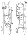
- Fig. 1 is a side view of a floor scrubbing machine which uses the present invention;
- Fig. 2 is a plan view of the scrub head of the machine of Fig. 1, showing its suspension in the scrubber;
- Fig. 3 is a longitudinal section view of the scrub head on line 3-3 of Fig. 2 with some parts in full and others broken away for clarity;
- Fig. 4 is a front view of the scrub head on line 4-4 of Fig. 2; and
- Fig. 5 is a diagram of the linkage used to transmit vertical force to the scrub head.
- All figures are schematic, showing only those parts related to the invention, and with many conventional parts omitted.
- Fig. 1 shows an industrial floor scrubbing machine, commonly referred to as a scrubber, and generally designated by the number 10. It utilizes the present invention, which will be described in detail. In all other respects, however, it is a conventional scrubber. The scrubber has a frame 11 which supports the various machine components and includes two
longitudinal members 13 along the sides of the machine. Only one of these is shown in Fig. 1; the other may be assumed to be similar and on the far side of the machine. It may be battery powered, with asingle front wheel 12 which is motor driven and is also steerable. Tworear wheels 14 support the rest of the weight. There is aseat 16 for an operator, a steering wheel 18 and suitable controls. There aretanks 20 for storage of clean and dirty scrubbing solution and avacuum pickup squeegee 22 for removing dirty water from the floor and putting it in a storage tank. All of these elements and their arrangement are conventional, and will be familiar to a person knowledgeable in the art. - The brushes, motors and related parts are assembled in a scrub head which is generally designated by the
number 24 in the drawings. The working tools of this scrubber are two disc type scrub brushes 26 rotating about vertical axes and driven by electric motors through reduction gears. This is a conventional arrangement, and so is only shown schematically in the drawings. The scrub head also includes means for applying scrubbing solution to the floor and suitable skirts for water control. These elements are conventional and so may be omitted in the drawings. The scrub head is mounted in a midship location under the frame of the scrubber between the front wheel and the rear wheels. It is attached to the scrubber primarily by two parallel ball jointedlinks 28 on each side. These are of the type commonly used in automotive tie rods. They keep the scrub head level fore and aft, but allow it to move up and down so it can be raised for transport and lowered for working. When in the working position it can rise or fall to follow the undulations of an uneven floor surface. They will also allow it to be moved laterally, which will be discussed later. - Vertical force is applied to the scrub head by an electric
linear actuator 30 or the like in Fig. 2 mounted longitudinally to the frame 11 generally under the center of the machine and acting through a spring loaded bell crank and linkage system. As best shown in Fig. 3,actuator 30 is connected to bell crank 32 bypivot pin 34. Bell crank 32 is pivotally attached to the frame 11 of the machine bypivot pin 36. Another bell crank 38 is also pivotally attached to the frame by thissame pivot pin 36. Bell crank 32 is moved byactuator 30, and this movement is transmitted to bell crank 38, but is cushioned bysprings guide bolt 44. The movement ofbell crank 38 is transmitted to the scrub head by two identical ball jointedlinks link 50. The action of these links will be described later. - As seen in Fig. 3, when
actuator 30 is extended it will cause bell crank 32 to move in a counterclockwise direction aroundpivot pin 36.Spring 42 will be compressed and will exert an increasing force on bell crank 38 that will tend to rotate it counterclockwise aroundpivot pin 36. This will tend to lift uplinks scrub head 24. If theactuator 30 continues to extend, bell crank 32 will continue to compressspring 42 untilstop bolt 51 contacts a surface ofbell crank 38. After that, further extension ofactuator 30 will cause bell cranks 32 and 38 to move counterclockwise as one, positively lifting thescrub head 24 and its attached scrub brushes 26 to a raised position for transport. - Still referring to Fig. 3, when
actuator 30 retracts it will move bell crank 32 in a clockwise direction. If the weight of the scrub head is being supported bybell crank 38, as during transport, then bell crank 38 will move clockwise with bell crank 32 until thebrushes 26 contact the floor and support the weight of the scrub head. Further retraction ofactuator 30 will compressspring 40 and throughguide bolt 44 will exert a further clockwise force on bell crank 38, which throughlinks actuator 30 will compress eitherspring 42 orspring 40 to exert a variable upward or downward force on the brushes. - US-A-4 757 566 teaches that a desired torque load in such brushes working against a floor can be maintained essentially constant by suitable electronic controls. The load current in the brush drive motors will vary as the torque developed by the brushes, and a device which senses this motor load current can be used to cause an actuator such as 30 to extend when the load current increases or retract when the load current decreases. This will vary the pressure of the brushes against the floor, which will vary the torque that they will develop. Thus a feedback loop can be used which will hold the brush torque essentially constant at a desired value. The
springs links - As mentioned earlier, the method used to permit scrubbing close to a wall without a scrubbing side brush is to laterally extend the
scrub head 24 out beyond one side of the machine frame, for example, about five inches. This will extend onebrush 26 to position 26′ as shown in Fig. 2, which places it in position to scrub as close to a wall as a side brush could do. The lateral position of the scrub head is controlled by anactuator 52 which is mounted transversely under the scrubber frame 11, best shown in Fig. 4. It is connected to a swinginglever 54 which is pivotally anchored to the scrubber frame. Agas spring 56 is connected between swinginglever 54 and one of the upstanding brackets on thescrub head 24. The gas spring is normally extended, but asteel cable 58 is also connected parallel to it betweenlever 54 and the scrub head bracket to keep the gas spring from extending quite to its full length. The cable mainly protects the internal elements of the gas spring by taking the tensile forces developed during retraction of the scrub head to normal position. Electronic controls are provided so that the operator can extendactuator 52 when it is desired to scrub along a wall, and retract it to its normal position under the scrubber frame at other times. Extension or retraction of theactuator 52 will be transmitted through swinginglever 54 andgas spring 56 orcable 58 to thescrub head 24. The gas spring will push it out and the cable will pull it back. There is anangled deflector plate 60 which is an integral part of the scrub head. It extends out far enough to serve as a bumper. If the extended scrub head strikes a fixed object theplate 60 will slide along it and push the scrub head back under the machine frame, thus generally avoiding damage to it. The gas spring will compress and the cable will go slack to allow this. After the obstacle has been passed the gas spring will extend until the cable becomes taut, thus automatically moving the scrub head out again. - It is common in scrubber design to apply skirting which drags on the floor along the sides of the scrub head to keep scrub water on the floor from spreading out sidewise. Such side skirts commonly curve inward somewhat at their rear ends to direct the water back to the pickup squeegee. This practice is followed in the scrubber of this invention, the only departure from standard practice being that the rear ends are brought farther inward than usual so that water on the floor will be channeled within the width of the pickup squeegee when the scrub head is in its extended position.
- As described earlier, there may be more or less vertical force applied to the scrub head in its working position by
actuator 30, which is coupled to the scrub head through a bell crank and linkage system. It is desirable to keep this force vertical for both the retracted and extended positions of the scrub head. Bell crank 38 is coupled to the scrub head with a linkage that delivers straight line lateral motion. As shown in Fig. 4 and diagrammatically in Fig. 5, there is a pivotedlink 50 rotatably mounted at itscenter 62 on the scrub head. There are two identical ball jointedlinks link 50 and bell crank 38. Comparing these parts to the geometry shown in Fig. 5, pivotedlink 50 compares to member BC, with thepivot center 62 oflink 50 comparing to point E. Ball jointedlink 46 compares to member AC, ball jointedlink 48 compares to member BD, and bell crank 38 compares to member AD. The length relationships indicated under Fig. 5,
pivot center 62 can and does move straight laterally between point E to E′ when the scrub head is moved in or out. Fig. 4 shows in solid lines the positions of the links when the scrub head is in normal position, and in phantom lines their positions when the scrub head is extended. A force analysis of this linkage system will show that a vertical force exerted by bell crank 38 will be transmitted by the linkage as a vertical force to pivotcenter 62 and thence to the scrub head without change, regardless of whether the scrub head is in normal position or extended position or in any intermediate position between normal and extended. - It is important in any scrubber that the brushes exert a uniform pressure on the floor over the entire area of contact between the brushes and the floor. This is done in the scrubber of the present invention by causing the center of the contact area of the brushes with the floor and the center of gravity of the scrub head assembly to both lie in one vertical line, and the vertical force applied by
actuator 30 to be applied in that same vertical line. That vertical line is shown aspoint 64 in Fig. 2, which is a plan view, so a vertical line appears as a point. Point orline 64 intersects a line connecting the centers ofbrushes line 64. Thepivot centerline 62 oflink 50 passes throughline 64. The ball jointedlinks link 50, which transmits it to the scrub head atcenterline 62, so the vertical force applied byactuator 30 is applied alongline 64. - Whereas the preferred form of the invention has been shown and described herein, it should be realized that there can be many modifications, substitutions and alterations thereto which would still fall within the scope of the invention.
Claims (12)
- A floor scrubbing machine (10) having a longitudinal center line, a frame (11), one or more front wheels (12) and one or more rear wheels (14) supporting the machine (10) for movement over the floor, a scrub head (24) movably attached to the frame (11), the scrub head (24) containing one or more rotating floor-engaging tools (26), means (52, 54, 56) for moving the scrub head (24) constructed and arranged so that it may be made to move laterally from a normal position where it is centered on the longitudinal center line of the machine (10) to any of various lateral working positions in which it may project a desired amount beyond at least one side of the frame (11), means (30-51, 62) on the frame (11) for applying a selectable down force other than gravity on the scrub head (24), characterized by means (38, 46, 48, 50, 62) for maintaining said selectable down force generally vertical regardless of the lateral position of the scrub head (24), and for ensuring that the magnitude of the force is not affected by the lateral position of the scrub head (24).
- The floor scrubbing machine (10) of claim 1 further characterized in that the center of area of that portion of the tools (26) in contact with the floor when in a working position and the center of weight of the scrub head (24) including tools (26) both coincide with the line of force (64) where the generally vertical force other than gravity is applied to the scrub head (24), regardless of the lateral position of the scrub head (24).
- The floor scrubbing machine (10) of claim 1 further characterized by and including means (58) for establishing a maximum laterally outward position of the scrub head (24) relative to the frame (11).
- The floor scrubbing machine (10) of claim 1 further characterized in that the means (52, 54, 56) for positioning the scrub head (24) in a selected lateral position are mounted on the frame (11) of the machine (10) and are connected to the scrub head (24) in a resilient manner so that the scrub head (24) may automatically retract to avoid damage if it strikes an object.
- The floor scrubbing machine (10) of claim 4 further characterized in that the resilient connection comprises a gas spring (56).
- The floor scrubbing machine (10) of claim 4 further characterized in that the scrub head (24) at its end which may extend outside the machine frame (11) is equipped with a bumper (60) that will deflect the scrub head (24) toward its normal position if it collides with a solid object.
- The floor scrubbing machine (10) of claim 1 further characterized in that the scrub head (24) is mounted under the machine frame (11) and amidships, being behind the front wheel (12) or wheels and ahead of the rear wheel or wheels (14) of the machine (10).
- The floor scrubbing machine (10) of claim 1 further characterized by and including yieldable means (40, 42) functionally cooperating with the means (30-51, 62) on the frame (11) for applying the selectable down force, so that the down force is resiliently applied.
- The floor scrubbing machine (10) of claim 1 further characterized by means for maintaining a constant selected torque on the tool or tools (26) when in contact with the floor.
- A method of operating a floor scrubbing machine (10) having a frame (11) and a scrub head (24) which contains one or more floor engaging tools (26) and is positioned on the frame (11), characterized by including the steps of positioning the scrub head (24) in a laterally offset position relative to the longitudinal centerline of the frame (11), and applying a vertical down force other than gravity between the frame (11) and the scrub head (24), resulting in a vertical down force other than gravity on the tools (26) on the floor, said down force being maintained constant during such lateral displacement.
- The method of claim 10 further characterized by and including the step of maintaining uniform torque on the tools (26).
- The method of claim 10 further characterized by and including the step of maintaining the center of area of that portion of the tools (26) in contact with the floor when in a working position and the center of weight of the scrub head (24) including tools (26) both coincident with the line of force (64) where the generally vertical force other than gravity is applied to the scrub head (24), regardless of the lateral position of the scrub head (24).
Applications Claiming Priority (2)
| Application Number | Priority Date | Filing Date | Title |
|---|---|---|---|
| US396132 | 1989-08-21 | ||
| US07/396,132 US5016310A (en) | 1989-08-21 | 1989-08-21 | Floor scrubber having laterally variable scrub brush position |
Publications (2)
| Publication Number | Publication Date |
|---|---|
| EP0415563A1 EP0415563A1 (en) | 1991-03-06 |
| EP0415563B1 true EP0415563B1 (en) | 1994-08-31 |
Family
ID=23565983
Family Applications (1)
| Application Number | Title | Priority Date | Filing Date |
|---|---|---|---|
| EP90308378A Expired - Lifetime EP0415563B1 (en) | 1989-08-21 | 1990-07-31 | Floor scrubber having laterally variable scrub brush position |
Country Status (4)
| Country | Link |
|---|---|
| US (1) | US5016310A (en) |
| EP (1) | EP0415563B1 (en) |
| JP (1) | JPH03191939A (en) |
| DE (1) | DE69012023T2 (en) |
Families Citing this family (34)
| Publication number | Priority date | Publication date | Assignee | Title |
|---|---|---|---|---|
| US5265300A (en) * | 1992-01-13 | 1993-11-30 | Aar Corp. | Floor scrubber |
| ATE171356T1 (en) * | 1993-11-17 | 1998-10-15 | Briscoe William A | BRUSH PRESSURE SYSTEM |
| US5605493A (en) * | 1994-04-19 | 1997-02-25 | Clarke Industries, Inc. | Stone polishing apparatus and method |
| US5483718A (en) * | 1994-10-03 | 1996-01-16 | Tennant Company | Floor scrubbing machine having impact energy absorption |
| GB9703528D0 (en) * | 1996-09-04 | 1997-04-09 | Briscoe William A | Surface working apparatus |
| US6006390A (en) * | 1997-10-31 | 1999-12-28 | The Toro Company | Connecting mechanism for attaching a ground-engaging surface maintenance implement to a traction vehicle |
| US6155907A (en) | 1998-10-30 | 2000-12-05 | Curecrete Chemical Company, Inc. | Method for hardening and polishing concrete floors, walls, and the like |
| GB2344751B (en) * | 1998-12-18 | 2002-01-09 | Notetry Ltd | Vacuum cleaner |
| US6202775B1 (en) * | 1999-03-03 | 2001-03-20 | Floorstyle Products, Inc. | Rotary floor finisher for use with a power rider trailer |
| US6530102B1 (en) | 1999-10-20 | 2003-03-11 | Tennant Company | Scrubber head anti-vibration mounting |
| US6763544B2 (en) | 2000-08-22 | 2004-07-20 | Alto Us, Inc. | Apparatus for treating a floor surface |
| US6760947B2 (en) | 2000-08-22 | 2004-07-13 | Alto U.S. Inc. | Apparatus for treating a floor surface utilizing a handle mounted traverse switch |
| US6557207B2 (en) | 2000-08-22 | 2003-05-06 | Alto U.S. Inc. | Squeegee assembly for a floor surface treatment apparatus |
| US20040221407A1 (en) * | 2001-07-30 | 2004-11-11 | Tennant Company | Cleaning liquid dispensing system |
| US6671925B2 (en) * | 2001-07-30 | 2004-01-06 | Tennant Company | Chemical dispenser for a hard floor surface cleaner |
| US8051861B2 (en) * | 2001-07-30 | 2011-11-08 | Tennant Company | Cleaning system utilizing purified water |
| US7051399B2 (en) * | 2001-07-30 | 2006-05-30 | Tennant Company | Cleaner cartridge |
| US20040040102A1 (en) * | 2001-07-30 | 2004-03-04 | Tennant Company | Foamed cleaning liquid dispensing system |
| US7337490B2 (en) * | 2002-10-11 | 2008-03-04 | Nilfisk-Advance, Inc. | Floor cleaning apparatus |
| US8029739B2 (en) * | 2003-07-30 | 2011-10-04 | Tennant Company | Ultraviolet sanitation device |
| US8028365B2 (en) * | 2003-09-02 | 2011-10-04 | Tennant Company | Hard and soft floor cleaning tool and machine |
| JP2008519657A (en) | 2004-11-12 | 2008-06-12 | テナント・カンパニー | Movable floor cleaner data communication |
| GB2437229A (en) * | 2005-04-07 | 2007-10-17 | Tennant Co | Hard and soft floor surface cleaner |
| BRPI0611656A2 (en) * | 2005-05-05 | 2011-05-31 | Tennant Co | floor sweeping and scrubbing machinery, and method of cleaning a surface |
| US8584294B2 (en) * | 2005-10-21 | 2013-11-19 | Tennant Company | Floor cleaner scrub head having a movable disc scrub member |
| IT1394430B1 (en) * | 2009-01-22 | 2012-06-15 | Nilfisk Advance Spa | REFINED FLOOR-DRYING MACHINE |
| RU2537161C1 (en) * | 2010-11-15 | 2014-12-27 | Альфред Кэрхер Гмбх Унд Ко.Кг | Mobile floor cleaning machine |
| WO2012145694A1 (en) * | 2011-04-21 | 2012-10-26 | Hall Aaron T | Scrub deck retraction apparatus |
| US9498099B2 (en) | 2012-02-16 | 2016-11-22 | Tennant Company | Surface maintenance vehicle with compact side brush assembly |
| EP2814371B1 (en) * | 2012-02-16 | 2018-06-06 | Tennant Company | Surface maintenance vehicle with compact cleaning head lift mechanism and suspension |
| JP2015534863A (en) * | 2012-11-19 | 2015-12-07 | ベットロック・アー・ゲー | Floor cleaning equipment |
| WO2016198044A2 (en) * | 2015-06-09 | 2016-12-15 | Hochschule für Technik und Wirtschaft Dresden | Working machine for mobile cleaning |
| CN110495823A (en) * | 2019-09-26 | 2019-11-26 | 路驰洁环保设备有限公司 | Electric sweeper side brush adjustable elastic reset structure |
| CN112426103B (en) * | 2020-11-19 | 2022-01-21 | 深圳市升阳升人居环境服务有限公司 | Obstacle-crossing robot with strong garbage cleaning function |
Family Cites Families (10)
| Publication number | Priority date | Publication date | Assignee | Title |
|---|---|---|---|---|
| US3436788A (en) * | 1967-07-27 | 1969-04-08 | Wayne Manufacturing Co | Streetsweeper vacuum pickup head assembly |
| US3702488A (en) * | 1970-09-15 | 1972-11-14 | Tennant Co | Scrubbing machine |
| DE2241901A1 (en) * | 1972-08-25 | 1974-03-07 | Raible Maschbau Kg Rudolf | SWEEPER VEHICLE WITH A CUTTLE DISC BROOM |
| US3981596A (en) * | 1974-01-09 | 1976-09-21 | Melton Systems, Inc. | Floor finish applicator |
| GB1592775A (en) * | 1976-11-18 | 1981-07-08 | Johnston Bros Eng Ltd | Refuse collecting vehicles |
| US4368554A (en) * | 1980-03-28 | 1983-01-18 | Hestair Eagle Limited | Road sweeping apparatus |
| GB2116613B (en) * | 1982-02-27 | 1985-07-24 | Schmidt Mfg & Equip | Road sweeping machine |
| US4506405A (en) * | 1983-09-29 | 1985-03-26 | Mcgraw-Edison Company | Floor treating machine |
| US4691402A (en) * | 1986-03-25 | 1987-09-08 | Veselka Kenneth R | Adjustable single lock gutter broom mechanism |
| US4757566A (en) * | 1987-07-27 | 1988-07-19 | Tennant Company | Control of torque in floor maintenance tools by drive motor load |
-
1989
- 1989-08-21 US US07/396,132 patent/US5016310A/en not_active Expired - Lifetime
-
1990
- 1990-07-31 EP EP90308378A patent/EP0415563B1/en not_active Expired - Lifetime
- 1990-07-31 DE DE69012023T patent/DE69012023T2/en not_active Expired - Fee Related
- 1990-08-21 JP JP2219906A patent/JPH03191939A/en active Pending
Also Published As
| Publication number | Publication date |
|---|---|
| EP0415563A1 (en) | 1991-03-06 |
| US5016310A (en) | 1991-05-21 |
| DE69012023T2 (en) | 1995-04-20 |
| JPH03191939A (en) | 1991-08-21 |
| DE69012023D1 (en) | 1994-10-06 |
Similar Documents
| Publication | Publication Date | Title |
|---|---|---|
| US5016310A (en) | Floor scrubber having laterally variable scrub brush position | |
| US4674944A (en) | Forklift variable reach mechanism | |
| US4803753A (en) | Self-propelled carpet scrubbing machine | |
| US4937900A (en) | Electric sofa bed | |
| EP2814369B1 (en) | Surface maintenance vehicle with compact side brush assembly | |
| US4483041A (en) | Support for a squeegee assembly | |
| EP0087936B1 (en) | Brush control means | |
| EP0629524A1 (en) | Vehicles and vehicle lifts | |
| KR102465684B1 (en) | Agricultural lift electric work car with foldable wheels | |
| US20020170130A1 (en) | Suspension for a surface maintenance appliance | |
| US6227569B1 (en) | Stabilizer mechanical support linkage | |
| CA1287328C (en) | Vehicle for remote handling of loads | |
| JP3133793B2 (en) | Lift / loader boom device and work tool moving method using lift / loader boom device | |
| CA2207767A1 (en) | Lost motion lift control for a mower deck | |
| US3515233A (en) | Articulated industrial truck | |
| US4437696A (en) | Movable truck bumper | |
| US4549326A (en) | Street sweeper with elevator conveyer adjustable in height with respect to the ground | |
| US6098719A (en) | Parallelogram boom devices for mounting agricultural implements to short wheel base tractors and adjusting implement position relative to ground | |
| JP2605726Y2 (en) | Work machine suspension system for riding type work vehicle | |
| EP1262138B1 (en) | Surface treating machine | |
| US7003841B2 (en) | Surface treating machine | |
| JP2524279Y2 (en) | Walking rice transplanter | |
| JP2649260B2 (en) | Truck drive mechanism | |
| JP3302933B2 (en) | Transport vehicle | |
| JP3730431B2 (en) | Mid-mount mower lifting link mechanism |
Legal Events
| Date | Code | Title | Description |
|---|---|---|---|
| PUAI | Public reference made under article 153(3) epc to a published international application that has entered the european phase |
Free format text: ORIGINAL CODE: 0009012 |
|
| AK | Designated contracting states |
Kind code of ref document: A1 Designated state(s): DE FR GB IT NL SE |
|
| 17P | Request for examination filed |
Effective date: 19910719 |
|
| 17Q | First examination report despatched |
Effective date: 19930422 |
|
| GRAA | (expected) grant |
Free format text: ORIGINAL CODE: 0009210 |
|
| AK | Designated contracting states |
Kind code of ref document: B1 Designated state(s): DE FR GB IT NL SE |
|
| ITF | It: translation for a ep patent filed | ||
| REF | Corresponds to: |
Ref document number: 69012023 Country of ref document: DE Date of ref document: 19941006 |
|
| ET | Fr: translation filed | ||
| EAL | Se: european patent in force in sweden |
Ref document number: 90308378.0 |
|
| PLBE | No opposition filed within time limit |
Free format text: ORIGINAL CODE: 0009261 |
|
| STAA | Information on the status of an ep patent application or granted ep patent |
Free format text: STATUS: NO OPPOSITION FILED WITHIN TIME LIMIT |
|
| 26N | No opposition filed | ||
| PGFP | Annual fee paid to national office [announced via postgrant information from national office to epo] |
Ref country code: FR Payment date: 19980618 Year of fee payment: 9 |
|
| PGFP | Annual fee paid to national office [announced via postgrant information from national office to epo] |
Ref country code: SE Payment date: 19980622 Year of fee payment: 9 |
|
| PGFP | Annual fee paid to national office [announced via postgrant information from national office to epo] |
Ref country code: DE Payment date: 19980625 Year of fee payment: 9 |
|
| PGFP | Annual fee paid to national office [announced via postgrant information from national office to epo] |
Ref country code: GB Payment date: 19980626 Year of fee payment: 9 |
|
| PGFP | Annual fee paid to national office [announced via postgrant information from national office to epo] |
Ref country code: NL Payment date: 19980629 Year of fee payment: 9 |
|
| PG25 | Lapsed in a contracting state [announced via postgrant information from national office to epo] |
Ref country code: SE Free format text: THE PATENT HAS BEEN ANNULLED BY A DECISION OF A NATIONAL AUTHORITY Effective date: 19990730 |
|
| PG25 | Lapsed in a contracting state [announced via postgrant information from national office to epo] |
Ref country code: GB Free format text: LAPSE BECAUSE OF NON-PAYMENT OF DUE FEES Effective date: 19990731 Ref country code: FR Free format text: THE PATENT HAS BEEN ANNULLED BY A DECISION OF A NATIONAL AUTHORITY Effective date: 19990731 |
|
| PG25 | Lapsed in a contracting state [announced via postgrant information from national office to epo] |
Ref country code: NL Free format text: LAPSE BECAUSE OF NON-PAYMENT OF DUE FEES Effective date: 20000201 |
|
| GBPC | Gb: european patent ceased through non-payment of renewal fee |
Effective date: 19990731 |
|
| NLV4 | Nl: lapsed or anulled due to non-payment of the annual fee |
Effective date: 20000201 |
|
| EUG | Se: european patent has lapsed |
Ref document number: 90308378.0 |
|
| PG25 | Lapsed in a contracting state [announced via postgrant information from national office to epo] |
Ref country code: DE Free format text: LAPSE BECAUSE OF NON-PAYMENT OF DUE FEES Effective date: 20000503 |
|
| REG | Reference to a national code |
Ref country code: FR Ref legal event code: ST |
|
| PG25 | Lapsed in a contracting state [announced via postgrant information from national office to epo] |
Ref country code: IT Free format text: LAPSE BECAUSE OF NON-PAYMENT OF DUE FEES;WARNING: LAPSES OF ITALIAN PATENTS WITH EFFECTIVE DATE BEFORE 2007 MAY HAVE OCCURRED AT ANY TIME BEFORE 2007. THE CORRECT EFFECTIVE DATE MAY BE DIFFERENT FROM THE ONE RECORDED. Effective date: 20050731 |