EP0415092B1 - Toroidal mounting for suspending engines in vehicles - Google Patents
Toroidal mounting for suspending engines in vehicles Download PDFInfo
- Publication number
- EP0415092B1 EP0415092B1 EP90114464A EP90114464A EP0415092B1 EP 0415092 B1 EP0415092 B1 EP 0415092B1 EP 90114464 A EP90114464 A EP 90114464A EP 90114464 A EP90114464 A EP 90114464A EP 0415092 B1 EP0415092 B1 EP 0415092B1
- Authority
- EP
- European Patent Office
- Prior art keywords
- stop
- hollow chambers
- side flange
- toroidal core
- core mounting
- Prior art date
- Legal status (The legal status is an assumption and is not a legal conclusion. Google has not performed a legal analysis and makes no representation as to the accuracy of the status listed.)
- Expired - Lifetime
Links
Images
Classifications
-
- F—MECHANICAL ENGINEERING; LIGHTING; HEATING; WEAPONS; BLASTING
- F16—ENGINEERING ELEMENTS AND UNITS; GENERAL MEASURES FOR PRODUCING AND MAINTAINING EFFECTIVE FUNCTIONING OF MACHINES OR INSTALLATIONS; THERMAL INSULATION IN GENERAL
- F16F—SPRINGS; SHOCK-ABSORBERS; MEANS FOR DAMPING VIBRATION
- F16F13/00—Units comprising springs of the non-fluid type as well as vibration-dampers, shock-absorbers, or fluid springs
- F16F13/04—Units comprising springs of the non-fluid type as well as vibration-dampers, shock-absorbers, or fluid springs comprising both a plastics spring and a damper, e.g. a friction damper
- F16F13/06—Units comprising springs of the non-fluid type as well as vibration-dampers, shock-absorbers, or fluid springs comprising both a plastics spring and a damper, e.g. a friction damper the damper being a fluid damper, e.g. the plastics spring not forming a part of the wall of the fluid chamber of the damper
- F16F13/24—Units comprising springs of the non-fluid type as well as vibration-dampers, shock-absorbers, or fluid springs comprising both a plastics spring and a damper, e.g. a friction damper the damper being a fluid damper, e.g. the plastics spring not forming a part of the wall of the fluid chamber of the damper the central part of the unit being supported by one element and both extremities of the unit being supported by a single other element, i.e. double acting mounting
Definitions
- the invention relates to a toroidal bearing for supporting drive units in motor vehicles with a hollow cylindrical suspension spring clamped between an engine-side and a body-side flange made of elastomeric material, and with a tension and pressure stop which fixes a suspension arm on the engine-side flange and releases the suspension spring and the body-side flange has penetrating bolt, at the free end of which an annular stop made of elastic material is arranged.
- Motor bearings of this type generally have a flat force-deformation characteristic and a progressive characteristic in the stop area.
- the suspension spring is generally made from a highly elastic elastomer.
- the present invention is therefore based on the object of creating a bearing of this type which, in addition to good insulation of higher-frequency vibrations, also has good damping when the stop engages, this damping being adjustable within wide limits.
- At least two approximately kidney-shaped, elastically deformable hollow chambers made of elastomeric material are defined as stop pads opposite one another on the top and bottom of a support plate fixed to the free bolt head, which are each filled with a liquid and via one of them Support plate penetrating overflow channel with each other.
- hollow chambers are designed as kidney-shaped half-shells, which are attached with their open side to the support plate.
- kidney-shaped hollow chambers have an approximately semicircular cross section with decreasing wall thickness towards the apex.
- the volume compliance of the hollow chamber decreases with increasing deformation due to the contact surface, so that the dynamic rigidity increases.
- the hollow chambers lying one behind the other on a circular line are expediently vulcanized onto a separate annular disk-shaped plate, which plates are clamped through the support plate and mutually braced.
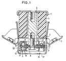
- a hollow cylindrical suspension spring 4 made of a highly elastic elastomer is clamped between a motor-side flange 1 and a body-side flange 2 with the corresponding screw-on part 3. With this suspension spring 4 fixed, not shown drive units are supported on the motor-side flange 1.
- Such a suspension spring 4 made of highly elastic material can effectively isolate higher-frequency vibrations of small amplitudes of the drive unit, but vibration damping - in particular if such a bearing comes into contact - is only inadequately given.
- a hydraulically damped pull and push stop 5 which is constructed as follows:
- a circular support plate 7 is screwed onto the free end 8 of a bolt 6, which is welded onto the motor-side flange 1 and passes freely through the hollow cylindrical suspension spring 4 and the body-side flange 2.
- This support plate 7 carries at least two kidney-shaped half-shell-shaped hollow chambers made of elastomeric material on the upper and lower sides, of which the upper hollow chamber 10 and the lower hollow chamber 13 can be seen in the section shown in FIG. 1.
- the interiors 16 and 17 are filled with a liquid and are connected to one another via an overflow channel 18 in the support plate 7.
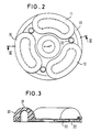
- 3 hollow chambers 10, 11 and 12 are arranged on a circular line on the support plate 7.
- the individual hollow chambers are expediently vulcanized onto a separate ring plate 20 or 21 from the top and bottom sides, which are then arranged on both sides of the support plate 7 and are clamped against one another in the circumferential direction by screws 22 between the individual hollow chambers 10, 11 and 12.
- This actual tension and pressure stop 5 is still enclosed by a pot-shaped housing 23 which is welded onto the underside of the flange 2 on the body side.
- the underside 25 of the body-side flange 2 forms the contact surface for the Stop in the pulling direction and the bottom 26 of the pot-shaped housing 23 the stop surface in the pressure direction.
- the stop stiffness tends to disappear when the deformation speed disappears against the comparatively low value of the pure component stiffness, i.e. the stroke behaves as if it were not filled.
- this condition corresponds to the deformation of the stop due to operating loads that have been present for a long time.
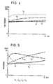
- FIG. 3 A particularly favorable embodiment of such hollow chambers is shown in the longitudinal section according to FIG. 3.
- the hollow chamber 30 shown in section has approximately one semicircular cross section with decreasing wall thickness to the apex 31 or continuously increasing wall thickness to the side flanks. In this way it is achieved that the volume compliance of the chamber 30 decreases with increasing deformation when it is in contact with a stop surface and thus the dynamic rigidity increases.
- the opposite, unloaded hollow chamber (not shown in detail), on the other hand, becomes softer in volume due to the similar geometry and can more easily absorb the displaced liquid. This design thus contributes to increasing the pressure drop required for the hydraulic damping.
- the viscosity of the liquid used in the hollow chambers is essential for the course of the dynamic rigidity and damping.
- such a unit bearing can not only optimally isolate high-frequency vibrations, but also specifically and sufficiently dampen higher-amplitude vibrations in which the bearing hits the stop.
Description
Die Erfindung bezieht sich auf ein Ringkernlager zur Abstützung von Antriebsaggregaten in Kraftfahrzeugen mit einer zwischen einem motorseitigen und einem karosserieseitigen Flansch eingespannten hohlzylindrischen Tragfeder aus elastomerem Material sowie mit einem Zug- und Druckanschlag, der einen am motorseitigen Flansch festgelegten und die Tragfeder und den karosserieseitigen Flansch frei durchsetzenden Bolzen aufweist, an dessen freiem Ende ein ringförmiger Anschlag aus elastischem Material angeordnet ist.The invention relates to a toroidal bearing for supporting drive units in motor vehicles with a hollow cylindrical suspension spring clamped between an engine-side and a body-side flange made of elastomeric material, and with a tension and pressure stop which fixes a suspension arm on the engine-side flange and releases the suspension spring and the body-side flange has penetrating bolt, at the free end of which an annular stop made of elastic material is arranged.
Derartige Motorlager weisen im allgemeinen eine flache Kraft-Verformungs-Kennlinie und eine progressive Kennung im Anschlagbereich auf. Um auch höherfrequente Vibrationen kleiner Amplitude des Motors zu isolieren wird im allgemeinen die Tragfeder aus einem hochelastischen Elastomer gefertigt.Motor bearings of this type generally have a flat force-deformation characteristic and a progressive characteristic in the stop area. In order to isolate even higher-frequency vibrations with a small amplitude of the motor, the suspension spring is generally made from a highly elastic elastomer.
Dabei ergeben sich jedoch folgende Probleme. Zum einen prallt bei stoßartigen Belastungen des Lagers dieses wegen der niedrigen Steifigkeit im Arbeitsbereich mit hoher Geschwindigkeit in den Anschlag und wird infolge fehlender Dämpfung wieder zurückgeworfen. Da hierbei dem schwingungsfähigen System nur wenig Energie entzogen wird, kommt es zu einem wiederholtem Eingreifen des Anschlages, was von den Fahrzeuginsassen als unangenehm empfunden wird. Darüber hinaus wird das Lager durch Betriebslasten wegen seiner niedrigen Steifigkeit im Arbeitsbereich aus dem Arbeitspunkt verschoben und es kommt zum Anliegen des Anschlags. Dadurch erhöht sich die Steifigkeit des Lagers, und die Isolation gegen Vibrationen wird verschlechtert.However, the following problems arise. On the one hand, if the bearing is subjected to sudden loads, it hits the stop at high speed due to the low rigidity in the work area and is thrown back due to the lack of damping. Since only a small amount of energy is withdrawn from the system capable of oscillation, the stop intervenes repeatedly, which is felt by the vehicle occupants as unpleasant becomes. In addition, the bearing is moved out of the working point due to its low rigidity in the working area due to operating loads and the stop comes to rest. This increases the rigidity of the bearing and the insulation against vibrations is deteriorated.
Auch durch eine entsprechend gewählte Geometrie des Anschlages und einer Abstimmung der Materialeigenschaften bezüglich Steifigkeit und Dämpfung können die dem Lager inhärenten Nachteile nicht befriedigend beseitigt werden. So führt eine Erhöhung der Materialdämpfung des Anschlags zu einer Verbesserung des Schwingungsabbaus, die jedoch bei lastbedingtem Anliegen des Anschlages an den Kontaktflächen mit einer Anhebung der Geräuschübertragung erkauft wird.The disadvantages inherent in the bearing cannot be satisfactorily eliminated even by an appropriately selected geometry of the stop and a coordination of the material properties with regard to rigidity and damping. Thus, an increase in the material damping of the stop leads to an improvement in the reduction of vibrations, which, however, is paid for when the stop is in contact with the load on the contact surfaces with an increase in the noise transmission.
Der vorliegenden Erfindung liegt daher die Aufgabe zugrunde, ein derartiges Lager zu schaffen, das neben einer guten Isolation höherfrequenter Vibrationen auch eine gute Dämpfung bei Eingreifen des Anschlages aufweist, wobei diese Dämpfung in weiten Grenzen einstellbar ist.The present invention is therefore based on the object of creating a bearing of this type which, in addition to good insulation of higher-frequency vibrations, also has good damping when the stop engages, this damping being adjustable within wide limits.
Zur Lösung dieser Aufgabe ist erfindungesgemäß vorgesehen, daß auf Ober- und Unterseite einer am freien Bolzenkopf festgelegten Tragplatte mindestens je zwei angenähert nierenförmige, elastisch verformbare Hohlkammern aus elastomerem Material als Anschlagpolster einander gegenüberliegend festgelegt sind, die jeweils mit einer Flüssigkeit gefüllt sind und über einen die Tragplatte durchdringenden Überströmkanal miteinander in Verbindung stehen.To solve this problem it is provided according to the invention that at least two approximately kidney-shaped, elastically deformable hollow chambers made of elastomeric material are defined as stop pads opposite one another on the top and bottom of a support plate fixed to the free bolt head, which are each filled with a liquid and via one of them Support plate penetrating overflow channel with each other.
Zweckmäßigerweise dient dabei als Zuganschlagfläche die Unterseite des karosserieseitigen Flansches und als Druckanschlag der Boden eines auf die Unterseite des karosserieseitigen Flansches aufgesetzen topfförmigen Gehäuses.The underside of the flange on the bodywork side and expediently serve as the train stop surface Pressure stop on the bottom of a pot-shaped housing placed on the underside of the body-side flange.
Damit kommt bei großen axialen Bewegungen des Lagers eine der Hohlkammern mit den Anschlagflächen in Berührung, so daß sie verformt und die Flüssigkeit durch die Überströmöffnung in die gegenüberliegende unbelastete Kammer verdrängt wird. Die dadurch bedingten Strömungsverluste entziehen der Aggregatbewegung Energie und bedämpfen sie damit. Durch eine entsprechende Auslegung von Geometrie und Volumennachgiebigkeit der Kammern, der Geometrie des Überströmkanals und der Viskosität der Flüssigkeit kann die Anschlagcharakteristik in weiten Bereichen entsprechend eingestellt werden.With large axial movements of the bearing, one of the hollow chambers thus comes into contact with the stop surfaces, so that it is deformed and the liquid is displaced through the overflow opening into the opposite unloaded chamber. The resulting flow losses draw energy from the aggregate movement and dampen it. Appropriate design of the geometry and volume compliance of the chambers, the geometry of the overflow channel and the viscosity of the liquid allow the stop characteristics to be set accordingly over a wide range.
Zweckmäßig ist es dabei, wenn die Hohlkammern als nierenförmige Halbschalen ausgebildet sind, die mit ihrer offenen Seite auf der Tragplatte befestigt sind.It is useful if the hollow chambers are designed as kidney-shaped half-shells, which are attached with their open side to the support plate.
Ein besonders günstiger Verlauf der dynamischen Steifigkeit ergibt sich dabei, wenn die nierenförmigen Hohlkammern angenähert halbkreisförmigen Querschnitt mit abnehmender Wandstärke zum Scheitelpunkt hin aufweisen. Dadurch nimmt die Volumennachgiebigkeit der Hohlkammer mit zunehmender Verformung durch die Kontaktfläche ab, so daß damit die dynamische Steifigkeit ansteigt.A particularly favorable course of the dynamic stiffness is obtained if the kidney-shaped hollow chambers have an approximately semicircular cross section with decreasing wall thickness towards the apex. As a result, the volume compliance of the hollow chamber decreases with increasing deformation due to the contact surface, so that the dynamic rigidity increases.
Zweckmäßigerweise sind die auf einer Kreislinie hintereinanderliegenden Hohlkammern einer Seite auf einer gesonderten ringscheibenförmigen Platte aufvulkanisiert, welche Platten durch die Tragplatte hindurch und gegenseitig verspannt sind.The hollow chambers lying one behind the other on a circular line are expediently vulcanized onto a separate annular disk-shaped plate, which plates are clamped through the support plate and mutually braced.
Eine optimale Gestaltung ergibt sich, wenn jeweils drei Hohlkammern auf einer Tragplattenseite angeordnet sind.An optimal design results when there are three Hollow chambers are arranged on a support plate side.
Anhand einer schematischen Zeichnung sind Aufbau und Funktionsweise von Ausführungsbeispielen nach der Erfindung näher erläutert. Dabei zeigen
- Fig. 1
- einen Längsschnitt durch ein Ringkernlager mit integriertem hydraulischem Anschlag,
- Fig. 2
- eine Aufsicht auf den oberen Anschlag mit drei nierenförmigen Hohlkammern
- Fig. 3
- einen Längsschnitt durch die Hohlkammern entsprechend der Schnittlinie III-III nach Fig. 2
- Fig. 4
- ein Diagramm über den Verlauf der dynamischen Steifigkeit bei Verwendung von Flüssigkeiten unterschiedlicher Viskosität und
- Fig. 5
- ein Diagramm über den Verlauf des Verlustfaktors ebenfalls bei Flüssigkeiten unterschiedlicher Viskosität
- Fig. 1
- a longitudinal section through a ring core bearing with an integrated hydraulic stop,
- Fig. 2
- a top view of the upper stop with three kidney-shaped hollow chambers
- Fig. 3
- a longitudinal section through the hollow chambers according to the section line III-III of FIG. 2nd
- Fig. 4
- a diagram of the course of the dynamic stiffness when using liquids of different viscosity and
- Fig. 5
- a diagram of the course of the loss factor also with liquids of different viscosity
Wie man aus Fig. 1 ersieht, ist zwischen einem motorseitigen Flansch 1 und einem karossierieseitigen Flansch 2 mit dem entsprechenden Anschraubteil 3 eine hohlzylindrische Tragfeder 4 aus einem hochelastischen Elastomer eingespannt. Mit dieser Tragfeder 4 werden auf dem motorseitigen Flansch 1 festgelegte, nicht näher dargestellte Antriebsaggregate abgestützt. Eine derartige Tragfeder 4 aus hochelastischem Material kann zwar höherfrequente Vibrationen kleiner Amplituden des Antriebsaggregats gut isolieren, eine Schwingungsdämpfung - insbesondere wenn ein solches Lager in den Anschlag geht - ist aber nur sehr unzureichend gegeben.As can be seen from Fig. 1, a hollow cylindrical suspension spring 4 made of a highly elastic elastomer is clamped between a motor-side flange 1 and a body-
Um diesen Nachteil zu beheben, ist ein hydraulisch gedämpfter Zug- und Druckanschlag 5 vorgesehen, der wie folgt aufgebaut ist:In order to remedy this disadvantage, a hydraulically damped pull and
Am freien Ende 8 eines Bolzens 6, der am motorseitigen Flansch 1 angeschweit ist und die hohlzylindrische Tragfeder 4 sowie den karosserieseitigen Flansch 2 frei durchsetzt, ist eine kreisförmige Tragplatte 7 angeschraubt. Diese Tragplatte 7 trägt ober- und unterseitig mindesteins zwei nierenförmig ausgebildete halbschalenförmige Hohlkammern aus elastomerem Material, von denen in dem in Fig. 1 dargestellten Schnitt jeweils die obere Hohlkammer 10 und die untere Hohlkammer 13 zu erkennen sind. Die Innenräume 16 und 17 sind mit einer Flüssigkeit gefüllt und stehen über einen Überströmkanal 18 in der Tragplatte 7 miteinander in Verbindung.A
Beim dargestellten Ausführungsbeispiel sind - wie man insbesondere aus der Aufsicht aus Fig. 2 ersieht - jeweils 3 Hohlkammern 10, 11 und 12 auf einer Kreislinie auf der Tragplatte 7 angeordnet.In the illustrated embodiment, as can be seen in particular from the top view in FIG. 2, 3
Zweckmäßigerweise sind die einzelnen Hohlkammern von Ober- und Unterseite zunächst auf eine gesonderte Ringplatte 20 bzw. 21 aufvulkanisiert, die dann beidseitig der Tragplatte 7 angeordnet und über Schrauben 22 in Umfangsrichtung zwischen den einzelnen Hohlkammern 10, 11 bzw. 12 gegeneinander verspannt sind.The individual hollow chambers are expediently vulcanized onto a
Dieser eigentliche Zug- und Druckanschlag 5 ist dabei noch von einem topfförmigen Gehäuse 23 umschlossen, das auf der Unterseite des karosserieseitigen Flansches 2 angeschweißt ist. Damit bildet also die Unterseite 25 des karosserieseitigen Flansches 2 die Kontaktfläche für den Anschlag in Zugrichtung und der Boden 26 des topfförmigen Gehäuses 23 die Anschlagfläche in Druckrichtung.This actual tension and
Bei großen implizierten Schwingungen des am Flansch 1 festgelegten Antriebsaggregates kommt nunmehr eine der Kammern 10 bzw. 13 in Berührung mit einer der Anschlagflächen 25 oder 26, wodurch die jeweilige Kammer 10 bzw. 13 verformt und die Flüssigkeit durch den Überströmkanal 18 in die gegenüberliegende unbelastete Kammer verdrängt wird. Das verlustbehaftete Überströmen der Flüssigkeit führt zu einem Druckanstieg in der verformten Kammer und damit zu einer Versteifung des Anschlags. Mit zunehmender Deformationsgeschwindigkeit des Anschlages findet die Flüssigkeit immer weniger Zeit, sich durch die Überströmöffnungen auszutauschen, so daß die Steifigkeit des Anschlages bis zu einem Wert ansteigt, der dem Fall der vollständig geschlossenen Kammer entspricht.In the case of large implied vibrations of the drive unit fixed to the flange 1, one of the
Dagegen strebt die Anschlagsteifigkeit bei verschwindender Deformationsgeschwindigkeit gegen den im Vergleich niedrigen Wert der reinen Bauteilsteifigkeit, d.h. der Anschlag verhält sich, als wäre er nicht gefüllt.On the other hand, the stop stiffness tends to disappear when the deformation speed disappears against the comparatively low value of the pure component stiffness, i.e. the stroke behaves as if it were not filled.
Diesem Zustand entspricht in der praktischen Anwendung die Verformung des Anschlages durch längere Zeit anstehende Betriebslasten.In practice, this condition corresponds to the deformation of the stop due to operating loads that have been present for a long time.
Die durch den Flüssigkeitsaustausch zwischen belasteter und unbelasteter Kammer 16 bzw. 17 bedingten Strömungsverluste entziehen dabei der Bewegung des Antriebsaggregats Energie und bedämpfen damit diese Bewegung.The flow losses caused by the liquid exchange between loaded and
Eine besonders günstige Ausgestaltung derartiger Hohlkammern ist im dem Längsschnitt nach Fig. 3 gezeigt. Die im Schnitt dargestellte Hohlkammer 30 weist einen in etwa halbkreisförmigen Querschnitt mit abnehmender Wandstärke zum Scheitelpunkt 31 bzw. kontinuierlich zunehmender Wandstärke zu den seitlichen Flanken hin auf. Auf diese Weise wird erreicht, daß die Volumennachgiebigkeit der Kammer 30 mit zunehmender Verformung beim Anliegen an einer Anschlagfläche abnimmt und damit die dynamische Steifigkeit ansteigt. Die gegenüberliegende, nicht näher dargestellte unbelastete Hohlkammer wird dagegen wegen der gleichartigen Geometrie volumenweicher und kann die verdrängte Flüssigkeit leichter aufnehmen. Damit trägt diese Gestaltung zur Erhöhung des für die hydraulische Dämpfung erforderlichen Druckgefälles bei.A particularly favorable embodiment of such hollow chambers is shown in the longitudinal section according to FIG. 3. The
Wesentlich für den Verlauf der dynamischen Steifigkeit und der Dämpfung ist dabei die Viskosität der verwendeten Flüssigkeit in den Hohlkammern. In Fig. 4 ist dabei der Verlauf der dynamischen Steifigkeit und in Fig. 5 der Verlauf des Verlustfaktors bzw. der Dämpfung über einem Frequenzband von 0 - 30 Hz aufgetragen und zwar für jeweils 4 Flüssigkeiten unterschiedlicher Viskosität, wobei die jeweils ausgezogene Kurve für eine Flüssigkeit mit der niedrigsten Viskosität ν₁ = 1.000 mm²/s, die gepunktete Linie für eine Flüssigkeit mit der höchsten Viskosität ν₄ = 1.000.000 mm²/s gilt, und die beiden anderen Flüssigkeiten dazwischenliegende Viskositäten von ν₂ = 10.000 und ν₃ = 100.000 mm²/s aufweisen.The viscosity of the liquid used in the hollow chambers is essential for the course of the dynamic rigidity and damping. 4 shows the course of the dynamic stiffness and in FIG. 5 the course of the loss factor or damping over a frequency band of 0-30 Hz, specifically for 4 liquids of different viscosities, the solid curve for a liquid with the lowest viscosity ν₁ = 1,000 mm² / s, the dotted line applies to a liquid with the highest viscosity ν₄ = 1,000,000 mm² / s, and the other two liquids have intermediate viscosities of ν₂ = 10,000 and ν₃ = 100,000 mm² / s .
Man sieht dabei sehr deutlich, daß mit zunehmender Viskosität auch die dynamische Steifigkeit eines derartiges Lagers ansteigt, während ab einem bestimmten Viskositätswert, bis zu dem die Dämpfung mit zunehmender Frquenz ansteigt, diese Dämpfung bei höherer Viskosität wieder absinkt, da einem schnellen Flüssigkeitsaustausch über die Überströmöffnung dann erhebliche Grenzen gesetzt sind.It can be seen very clearly that the dynamic stiffness of such a bearing also increases with increasing viscosity, while from a certain viscosity value up to which the damping increases with increasing frequency, this damping decreases again with higher viscosity, since a rapid fluid exchange via the overflow opening then there are considerable limits.
Mit der beschriebenen Ausgestaltung eines hydraulisch wirkenden Anschlages kann also ein deratiges Aggregatlager nicht nur hochfrequente Vibrationen optimal isolieren, sondern auch höheramplitudige Schwingungen, bei denen das Lager in den Anschlag geht, gezielt und ausreichend bedämpfen.With the described configuration of a hydraulically acting stop, such a unit bearing can not only optimally isolate high-frequency vibrations, but also specifically and sufficiently dampen higher-amplitude vibrations in which the bearing hits the stop.
Claims (6)
- Toroidal core mounting for supporting drive units in motor vehicles, having a hollow cylindrical suspension spring (4) made of elastomeric material, which is clamped between an engine-side flange (1) and a body-side flange (2), as well as having a tension and compression stop (5) with a bolt (6) which is fastened to the engine-side flange (1), freely penetrates the suspension spring (4) and the body-side flange (2) and on whose free end (8) an annular stop (5) made of elastic material is disposed, characterized in that at least two approximately kidney-shaped, elastically deformable hollow chambers (10; 13) made of elastomeric material are fastened opposite one another as stop pads to the top and underside of a supporting plate (7) fastened to the free bolt head (8), said hollow chambers each being filled with a liquid and communicating with one another via an overflow channel (18) which penetrates the supporting plate (7).
- Toroidal core mounting according to claim 1, characterized in that the underside of the body-side flange (2) is provided as a tension stop face (25) and the base (27) of a pot-shaped housing (23) placed onto the underside of the body-side flange (2) serves as a compression stop face (26).
- Toroidal core mounting according to claim 1 or 2, characterized in that the hollow chambers (10, 11, 12; 13) take the form of kidney-shaped half shells which are fastened by their open side to the supporting plate (7).
- Toroidal core mounting according to claim 1 or 3, characterized in that the kidney-shaped hollow chambers (30) are approximately semicircular in cross-section with a decreasing wall thickness towards the apex (31).
- Toroidal core mounting according to one of claims 1 to 4, characterized in that the hollow chambers (10, 11, 12; 30) of one side, which lie one behind the other along a circular line, are vulcanized on a separate ring-wheel-shaped plate (20; 21), said plates (20; 21) being braced through the supporting plate (7) and reciprocally.
- Toroidal core mounting according to one or more of claims 1 to 5, characterized in that three hollow chambers (10, 11, 12) are disposed on each side of the supporting plate.
Applications Claiming Priority (2)
| Application Number | Priority Date | Filing Date | Title |
|---|---|---|---|
| DE3929099 | 1989-09-01 | ||
| DE3929099A DE3929099C1 (en) | 1989-09-01 | 1989-09-01 |
Publications (2)
| Publication Number | Publication Date |
|---|---|
| EP0415092A1 EP0415092A1 (en) | 1991-03-06 |
| EP0415092B1 true EP0415092B1 (en) | 1993-09-15 |
Family
ID=6388451
Family Applications (1)
| Application Number | Title | Priority Date | Filing Date |
|---|---|---|---|
| EP90114464A Expired - Lifetime EP0415092B1 (en) | 1989-09-01 | 1990-07-27 | Toroidal mounting for suspending engines in vehicles |
Country Status (4)
| Country | Link |
|---|---|
| EP (1) | EP0415092B1 (en) |
| JP (1) | JPH0392637A (en) |
| DE (2) | DE3929099C1 (en) |
| ES (1) | ES2044340T3 (en) |
Families Citing this family (2)
| Publication number | Priority date | Publication date | Assignee | Title |
|---|---|---|---|---|
| DE10117443B4 (en) * | 2001-04-03 | 2007-07-12 | Woco Industrietechnik Gmbh | Solid bearing |
| CN109278520A (en) * | 2018-11-30 | 2019-01-29 | 重庆长安汽车股份有限公司 | A kind of suspension of zero stiffness and automobile |
Family Cites Families (10)
| Publication number | Priority date | Publication date | Assignee | Title |
|---|---|---|---|---|
| DE684075C (en) * | 1936-03-06 | 1939-11-22 | Demag Akt Ges | Fluid damping for sliding armature motors |
| US2540130A (en) * | 1945-01-10 | 1951-02-06 | Norman E Lee | Support |
| US2582998A (en) * | 1945-07-07 | 1952-01-22 | Norman E Lee | Fluid damped resilient mounting |
| DE2309276A1 (en) * | 1973-02-24 | 1974-08-29 | Volkswagenwerk Ag | GAS SPRING ARRANGEMENT |
| DE3010723C2 (en) * | 1980-03-20 | 1983-01-20 | Boge Gmbh, 5208 Eitorf | Hydraulically damping bearing |
| DE3742340A1 (en) * | 1987-01-19 | 1988-07-28 | Volkswagen Ag | Bearing insulated against structure-borne sound, particularly for an internal-combustion engine |
| FR2613799B1 (en) * | 1987-04-13 | 1990-12-07 | Peugeot | HYDROELASTIC SUPPORT, IN PARTICULAR FOR THE SUSPENSION OF A VEHICLE ENGINE |
| DE3808996A1 (en) * | 1988-03-17 | 1989-09-28 | Metzeler Gmbh | HYDRAULIC DAMPING TWO CHAMBER - ENGINE MOUNT |
| FR2635155B1 (en) * | 1988-08-04 | 1990-11-09 | Hutchinson | IMPROVEMENTS ON ELASTIC SUPPORTS INCLUDING MEANS OF STOP |
| DE3836191C1 (en) * | 1988-10-24 | 1989-11-09 | Woco Franz-Josef Wolf & Co, 6483 Bad Soden-Salmuenster, De |
-
1989
- 1989-09-01 DE DE3929099A patent/DE3929099C1/de not_active Expired - Fee Related
-
1990
- 1990-07-27 EP EP90114464A patent/EP0415092B1/en not_active Expired - Lifetime
- 1990-07-27 ES ES90114464T patent/ES2044340T3/en not_active Expired - Lifetime
- 1990-07-27 DE DE90114464T patent/DE59002719D1/en not_active Expired - Fee Related
- 1990-08-29 JP JP2227865A patent/JPH0392637A/en active Pending
Also Published As
| Publication number | Publication date |
|---|---|
| DE59002719D1 (en) | 1993-10-21 |
| DE3929099C1 (en) | 1990-12-20 |
| JPH0392637A (en) | 1991-04-17 |
| EP0415092A1 (en) | 1991-03-06 |
| ES2044340T3 (en) | 1994-01-01 |
Similar Documents
| Publication | Publication Date | Title |
|---|---|---|
| DE2802896C2 (en) | Rubber mounts with hydraulic damping | |
| EP0044545B1 (en) | Engine mounting with two hydraulic damping chambers | |
| DE2736188C3 (en) | Rubber mount with hydraulic damping | |
| EP0164081A2 (en) | Double chamber hydraulic motor damping support | |
| DE3920891A1 (en) | FLUID-FILLED, ELASTOMERIC DAMPING DEVICE | |
| DE3116600A1 (en) | Engine mounting arrangement | |
| DE3340152A1 (en) | FASTENING ARRANGEMENT FOR A MOTOR GEARBOX | |
| DE4111318A1 (en) | HYDRAULIC, SOCKET SHAPED DAMPING DEVICE | |
| DE4106838A1 (en) | DAMPING AGGREGATE BEARING | |
| DE4131771A1 (en) | ELASTIC MOTOR MOUNT | |
| DE3342300A1 (en) | HYDRAULICALLY DAMPED TWO-CHAMBER BEARING | |
| DE3920153C2 (en) | ||
| DE3405907C2 (en) | ||
| DE3730582C2 (en) | ||
| EP0415001A1 (en) | Hydraulic support | |
| DE3828132A1 (en) | ELASTIC SUSPENSION WITH A LIQUID FILLING | |
| DE3730425A1 (en) | HYDRAULIC DAMPING ENGINE MOUNT | |
| DE2616258A1 (en) | IC engine hydraulically damped rubber bearing - has rigid plate supported rubber elastic parts and damping fluid working spaces | |
| DE2929084C2 (en) | Vibration dampening bearing | |
| EP0415092B1 (en) | Toroidal mounting for suspending engines in vehicles | |
| DE3712656C2 (en) | ||
| DE2933726A1 (en) | Vibration damper for machine part oscillating linear motion - has mass in viscoelastic liq., whose physical parameters meet specified equation | |
| EP0364662B1 (en) | Rubber mount | |
| DE2717825A1 (en) | Three=dimensional antivibration mounting - with hemispheres filled with plastisol and joined by variable nozzle | |
| DE19502242C1 (en) | Engine mounting with hollow cylindrical support spring |
Legal Events
| Date | Code | Title | Description |
|---|---|---|---|
| PUAI | Public reference made under article 153(3) epc to a published international application that has entered the european phase |
Free format text: ORIGINAL CODE: 0009012 |
|
| 17P | Request for examination filed |
Effective date: 19900727 |
|
| AK | Designated contracting states |
Kind code of ref document: A1 Designated state(s): DE ES FR GB IT SE |
|
| RAP1 | Party data changed (applicant data changed or rights of an application transferred) |
Owner name: METZELER GIMETALL AG |
|
| 17Q | First examination report despatched |
Effective date: 19930305 |
|
| GRAA | (expected) grant |
Free format text: ORIGINAL CODE: 0009210 |
|
| AK | Designated contracting states |
Kind code of ref document: B1 Designated state(s): DE ES FR GB IT SE |
|
| REF | Corresponds to: |
Ref document number: 59002719 Country of ref document: DE Date of ref document: 19931021 |
|
| ITF | It: translation for a ep patent filed |
Owner name: ING. C. GREGORJ S.P.A. |
|
| GBT | Gb: translation of ep patent filed (gb section 77(6)(a)/1977) |
Effective date: 19930928 |
|
| REG | Reference to a national code |
Ref country code: ES Ref legal event code: FG2A Ref document number: 2044340 Country of ref document: ES Kind code of ref document: T3 |
|
| ET | Fr: translation filed | ||
| PLBE | No opposition filed within time limit |
Free format text: ORIGINAL CODE: 0009261 |
|
| STAA | Information on the status of an ep patent application or granted ep patent |
Free format text: STATUS: NO OPPOSITION FILED WITHIN TIME LIMIT |
|
| PGFP | Annual fee paid to national office [announced via postgrant information from national office to epo] |
Ref country code: SE Payment date: 19940731 Year of fee payment: 5 |
|
| 26N | No opposition filed | ||
| EAL | Se: european patent in force in sweden |
Ref document number: 90114464.2 |
|
| PG25 | Lapsed in a contracting state [announced via postgrant information from national office to epo] |
Ref country code: SE Effective date: 19950728 |
|
| EUG | Se: european patent has lapsed |
Ref document number: 90114464.2 |
|
| PGFP | Annual fee paid to national office [announced via postgrant information from national office to epo] |
Ref country code: GB Payment date: 19960708 Year of fee payment: 7 |
|
| PGFP | Annual fee paid to national office [announced via postgrant information from national office to epo] |
Ref country code: FR Payment date: 19960716 Year of fee payment: 7 |
|
| PGFP | Annual fee paid to national office [announced via postgrant information from national office to epo] |
Ref country code: ES Payment date: 19960729 Year of fee payment: 7 |
|
| PGFP | Annual fee paid to national office [announced via postgrant information from national office to epo] |
Ref country code: DE Payment date: 19960924 Year of fee payment: 7 |
|
| PG25 | Lapsed in a contracting state [announced via postgrant information from national office to epo] |
Ref country code: GB Free format text: LAPSE BECAUSE OF NON-PAYMENT OF DUE FEES Effective date: 19970727 |
|
| PG25 | Lapsed in a contracting state [announced via postgrant information from national office to epo] |
Ref country code: ES Free format text: LAPSE BECAUSE OF THE APPLICANT RENOUNCES Effective date: 19970728 |
|
| GBPC | Gb: european patent ceased through non-payment of renewal fee |
Effective date: 19970727 |
|
| PG25 | Lapsed in a contracting state [announced via postgrant information from national office to epo] |
Ref country code: FR Free format text: LAPSE BECAUSE OF NON-PAYMENT OF DUE FEES Effective date: 19980331 |
|
| PG25 | Lapsed in a contracting state [announced via postgrant information from national office to epo] |
Ref country code: DE Free format text: LAPSE BECAUSE OF NON-PAYMENT OF DUE FEES Effective date: 19980401 |
|
| REG | Reference to a national code |
Ref country code: FR Ref legal event code: ST |
|
| REG | Reference to a national code |
Ref country code: ES Ref legal event code: FD2A Effective date: 20001102 |
|
| PG25 | Lapsed in a contracting state [announced via postgrant information from national office to epo] |
Ref country code: IT Free format text: LAPSE BECAUSE OF NON-PAYMENT OF DUE FEES;WARNING: LAPSES OF ITALIAN PATENTS WITH EFFECTIVE DATE BEFORE 2007 MAY HAVE OCCURRED AT ANY TIME BEFORE 2007. THE CORRECT EFFECTIVE DATE MAY BE DIFFERENT FROM THE ONE RECORDED. Effective date: 20050727 |