EP0414958A1 - Spanneinrichtung an Werkzeugmaschinen - Google Patents
Spanneinrichtung an Werkzeugmaschinen Download PDFInfo
- Publication number
- EP0414958A1 EP0414958A1 EP89119302A EP89119302A EP0414958A1 EP 0414958 A1 EP0414958 A1 EP 0414958A1 EP 89119302 A EP89119302 A EP 89119302A EP 89119302 A EP89119302 A EP 89119302A EP 0414958 A1 EP0414958 A1 EP 0414958A1
- Authority
- EP
- European Patent Office
- Prior art keywords
- guide rod
- axially
- clamping device
- distributor
- guide
- Prior art date
- Legal status (The legal status is an assumption and is not a legal conclusion. Google has not performed a legal analysis and makes no representation as to the accuracy of the status listed.)
- Granted
Links
Images


Classifications
-
- B—PERFORMING OPERATIONS; TRANSPORTING
- B23—MACHINE TOOLS; METAL-WORKING NOT OTHERWISE PROVIDED FOR
- B23Q—DETAILS, COMPONENTS, OR ACCESSORIES FOR MACHINE TOOLS, e.g. ARRANGEMENTS FOR COPYING OR CONTROLLING; MACHINE TOOLS IN GENERAL CHARACTERISED BY THE CONSTRUCTION OF PARTICULAR DETAILS OR COMPONENTS; COMBINATIONS OR ASSOCIATIONS OF METAL-WORKING MACHINES, NOT DIRECTED TO A PARTICULAR RESULT
- B23Q17/00—Arrangements for observing, indicating or measuring on machine tools
- B23Q17/002—Arrangements for observing, indicating or measuring on machine tools for indicating or measuring the holding action of work or tool holders
- B23Q17/003—Arrangements for observing, indicating or measuring on machine tools for indicating or measuring the holding action of work or tool holders by measuring a position
-
- Y—GENERAL TAGGING OF NEW TECHNOLOGICAL DEVELOPMENTS; GENERAL TAGGING OF CROSS-SECTIONAL TECHNOLOGIES SPANNING OVER SEVERAL SECTIONS OF THE IPC; TECHNICAL SUBJECTS COVERED BY FORMER USPC CROSS-REFERENCE ART COLLECTIONS [XRACs] AND DIGESTS
- Y10—TECHNICAL SUBJECTS COVERED BY FORMER USPC
- Y10T—TECHNICAL SUBJECTS COVERED BY FORMER US CLASSIFICATION
- Y10T279/00—Chucks or sockets
- Y10T279/12—Chucks or sockets with fluid-pressure actuator
- Y10T279/1208—Chucks or sockets with fluid-pressure actuator with measuring, indicating or control means
Definitions
- the invention relates to a clamping device on machine tools with a revolving clamping cylinder and an axially displaceable clamping piston arranged therewith, also with a distributor, which has a distributor housing carrying the connections for the working medium and a distributor shaft connected to the clamping piston and axially displaceable in the wall of the clamping cylinder comprises, on which the distributor housing is arranged so that the distributor shaft can rotate therein and takes the distributor housing along with the axial displacements of the tensioning piston, and with a control device for the axial displacements of the tensioning piston, consisting of at least one contact piece and at least one actuatable switching element, of which the switching element is connected to the distributor housing and the switching piece is connected to a cantilever which is axially displaceably guided on the distributor housing and by means of a Clamping cylinder arranged bearing against axial displacements is fixed relative to the clamping cylinder, for which purpose the bearing has a coaxial, rotatable and axially immovable bearing ring with respect to the
- Clamping devices of this type are known from DE 31 17 850 A1.
- the boom is a flat slide that runs in the guide grooves of a guide body arranged on the distributor housing.
- the flat slide is firmly connected with its end facing the clamping cylinder to a ring which is divided in the radial central plane.
- Both ring parts are axially clamped by screws and radially overlap the bearing ring with one ring shoulder each, so that the bearing ring is firmly clamped between these ring shoulders.
- This arrangement is not only complex in terms of the design of the longitudinal guide for the boom, but also requires a very precise coordination between the radial distance of the longitudinal guide of the boom from the axis of the distributor shaft on the one hand and the diameter of the bearing ring on the other.
- the invention is based on the object of designing a tensioning device of the type mentioned at the outset in such a way that it enables exact monitoring of the tensioning piston movements with a structurally and production-technically simple construction.
- the boom has at least one axially extending guide rod which is radially displaceably connected to the bearing ring and is arranged in coaxial guide openings which are located in guide lugs which are axially spaced apart on the distributor housing.
- the guide rod can carry the contact piece directly.
- a preferred embodiment of the invention is characterized in that the guide rod has at its end facing the clamping cylinder two flanges which receive the bearing ring in an axially positive and radially displaceable manner between them. It is recommended that that the bearing ring on the side of the distributor housing is formed as a flange arranged coaxially on the guide rod, which is axially displaceably guided on the guide rod and is pressed by a spring against the bearing ring. Due to the resilient pressure of the ring flange against the bearing ring, the desired axial play between the bracket and the bearing ring is readily obtained.
- the guide rod can have an annular shoulder which limits the displacement of the flange against the action of the spring, which enables the ring flange to be preassembled on the guide rod, in particular if, according to a further proposal of the invention, the spring is supported against a spring ring embedded in an annular groove of the guide rod and is designed as a plate spring.
- the bearing ring is expediently secured against rotation on the cantilever, for which purpose the guide rod has a pin with a circular cross section between the flanges which engages radially in a recess provided on the bearing ring.
- the guide openings for the boom are then easy to manufacture holes. It is also prevented that the switching pieces can rotate relative to the switching elements.
- the switching piece is designed as a switching ring which can be axially displaced on the guide rod and which can be fixed on the guide rod by means of an adjusting screw guided radially in the switching ring.
- This offers the possibility of arranging several switching elements offset over the circumference of the guide rod or the switching ring.
- the distributor housing carries a hood covering the guide rod for receiving the switching element.
- several mounting slots running parallel to the direction of adjustment of the guide rod are provided in the wall of the hood, and that the switching element can be moved along the mounting slots between the guide lugs and can be locked at the edges of the mounting slots.
- control options for the tensioning piston movement are very versatile and easily adaptable to all tasks.
- Another advantageous possibility is characterized in that several guide rods and guide lugs are arranged distributed over the circumference of the distributor housing. The ends of the guide rods facing away from the clamping cylinder and projecting axially beyond the distributor housing can be connected by a plate which is designed as a carrier of a stop rod which, in the case of a clamping cylinder with a free passage, projects axially into the hollow distributor shaft in order to provide a stop for rod-shaped workpieces form.
- the clamping cylinder 1 shown in the drawing for clamping devices on machine tools has a cylinder housing 3 with a clamping piston 2 which can be displaced therein and which can be connected to a clamping rod (not shown). Normally, the cylinder housing 3 is attached to the end of the machine tool spindle, not shown, and rotates with it, including the tensioning piston 2.
- a distributor is connected to the tensioning cylinder 1.
- This distributor 4 has a distributor housing 5 which does not rotate with the clamping cylinder 1 and which carries laterally lying connections 6 for the working medium actuating the clamping cylinder 1.
- a distributor shaft 7 rotates in the distributor housing 5 and is mounted in the distributor housing 5 by means of bearings 8, 9.
- the bearing 9 lies axially on a shoulder 10 of the distributor shaft 7, the bearing 8 on the other side against a locking ring 11, so that the distributor housing 5 is held axially immovably on the distributor shaft 7.
- the distributor shaft 7 is fixedly connected to the tensioning piston 2 and is axially displaceably mounted in the wall of the tensioning cylinder 1. As a result, an adjustment of the tensioning piston 2 in the axial direction remains unchanged via the distributor shaft 7 on the Transfer distributor housing 5.
- the circumferential grooves 12, 13 on the inside of the distributor housing 5 serve for the supply and discharge of the working medium and are connected to the connections 6 for the working medium. Leakage oil passing through between the distributor shaft 7 and the distributor housing 5 is collected in the channel 14 and discharged through the connection 15.
- the distributor shaft 7 has two shaft channels 18, 19 which lead into the clamping cylinder 1 on opposite sides of the clamping piston 2 and which are connected to the annular grooves 12, 13. The control of the working medium by the shaft channels 18, 19 either on one of the two sides of the tensioning piston 2 takes place in the usual way and does not require any description.
- a control device which consists of a plurality of switching elements 20, for example contact switches, and a switching element 21 for actuating the switching elements 20.
- the switching elements 20 are connected to the distributor housing 5 and take part in its axial displacements.
- a guide rod 29 is axially displaceably guided on the distributor housing 5 in a longitudinal guide and carries the switching element 21.
- the axial fixing of the guide rod 29 takes place on the tensioning cylinder 1 with the aid of an annular ball bearing 24.
- the tensioning cylinder 1 has on its end face facing the distributor 4 an annular collar 23 on which the annular ball bearing 24 coaxial to the tensioning cylinder 1 is arranged. It has a rotatable relative to the clamping cylinder 1 and axially immovable bearing ring 22.
- the bearing 24 is arranged on the annular collar 23 between an annular shoulder 25 and a retaining ring 26.
- the bearing ring 22 itself engages in an axially positive and radially displaceable manner between two flanges 27, 28 which are arranged axially next to one another on the guide rod 28 at its end facing the clamping cylinder 1 with a mutual free spacing.
- the guide rod 29 is secured by its longitudinal guide on the distributor housing 5 against rotating entrainment by the clamping cylinder 1.
- two guide lugs 33 which are formed on the distributor housing 5 and have guide openings 31 which receive the guide rod 29, serve to form the longitudinal guide for the guide rod 29.
- the guide openings 31, like the guide rod 29, are themselves circular in cross section.
- the flange 27 abutting the bearing ring 22 on the side of the tensioning cylinder 21 is designed as a front flange which delimits the guide rod 29 and is coaxial with it and is firmly connected to the guide rod.
- the flange 28 abutting the bearing ring 22 on the side of the distributor housing 5 is designed as an annular flange which is guided axially displaceably on the guide rod 29 and is pressed against the bearing ring 22 by a spring 30.
- the guide rod 29 carries an annular shoulder 34 which limits the displacement of the flange 28 against the action of the spring 30 and a spring ring 35 embedded in an annular groove of the guide rod 29, against which the spring 30 designed as a plate spring is axially supported.
- the bearing ring 22 is axially free of play with the guide rod 29 connected.
- the bearing ring 22 is secured against rotation on the guide rod 29, for which purpose the guide rod 29 has a pin 36 between the flanges 27, 28 which engages radially in a pocket-like recess 37 provided on the bearing ring 22.
- the switching piece 21 is an axially displaceable switching ring on the guide rod 29. It can be determined in the desired position with a set screw 38 guided radially in the switching ring on the guide rod 29. Of course, a plurality of switching pieces 21 can also be provided along the guide rod 29.
- the distributor housing 5 has on the side flange surfaces 41 a hood 39 fastened with screws 42, which overlaps the guide rod 29 from above and laterally.
- a plurality of mounting slots 40 running parallel to the direction of adjustment of the guide rod 29 are provided. The switching elements 20 can be displaced along these mounting slots 40 between the guide lugs 32 and can be fixed at the edges of the mounting slots 40 by means of clamping nuts 42.
- the mounting slots 40 are each located in strip-shaped flat wall areas of the hood 39, these wall areas each being inclined towards one another and following a polygonal cross section in the hood.
- the inclination of these strip-shaped wall areas of the hood 39 determines the angular orientation of the switching elements 20 over the circumference of the guide rod 29.
- the difference according to FIGS. 3 and 4 essentially differs from the embodiment according to FIGS. 1 and 2 in that several guide rods 29, namely a total of three guide rods, extend over the circumference of the distributor housing 5 are distributed.
- Two separate guide lugs 32 with guide openings 31 are provided for each guide rod 29.
- Each of these guide rods 29 is connected to the bearing ring 22 in a radially displaceable manner and can serve as a carrier for switching pieces 21 if corresponding hoods 39 are assigned to the guide rod as switching element carriers. In the exemplary embodiment, however, as in FIGS. 1 and 2, this is only shown for a single guide rod 29.
- 3 and 4 further show the case in which the ends of the guide rods 29 facing away from the tensioning cylinder 1 project axially beyond the distributor housing 5 and are connected by a plate 50, which through a central opening and an annular chuck 51 as a carrier for a not shown Stop rod is formed. If - as in the exemplary embodiments - the clamping cylinder has a free passage for machining rod-shaped workpieces, the stop rod can protrude axially into the hollow distributor shaft 7 and form a stop for the workpiece.
- the guide rods 29 are rigidly connected to one another by the plate 50 or the like, it is also sufficient to connect only a single guide rod 29 to the bearing ring 22 in order to secure all other guide rods 29 against axial displacements .
Landscapes
- Engineering & Computer Science (AREA)
- Mechanical Engineering (AREA)
- Jigs For Machine Tools (AREA)
- Actuator (AREA)
- Gripping On Spindles (AREA)
Abstract
Description
- Die Erfindung betrifft eine Spanneinrichtung an Werkzeugmaschinen mit einem umlaufenden Spannzylinder und einem darin mitumlaufend angeordneten, axial verschiebbaren Spannkolben, ferner mit einem Verteiler, der ein die Anschlüsse für das Arbeitsmedium tragendes Verteilergehäuse und eine mit dem Spannkolben verbundene und in der Wand des Spannzylinders axial verschiebbare Verteilerwelle umfaßt, auf der das Verteilergehäuse so angeordnet ist, daß die Verteilerwelle darin umlaufen kann und das Verteilergehäuse bei den Axialverschiebungen des Spannkolbens mitnimmt, und mit einer Kontrolleinrichtung für die Axialverschiebungen des Spannkolbens, bestehend aus mindestens einem Schaltstück und mindestens einem davon betätigbaren Schaltglied, von welchen das Schaltglied mit dem Verteilergehäuse und das Schaltstück mit einem Ausleger verbunden ist, der am Verteilergehäuse axial längsverschieblich geführt ist und mittels eines am Spannzylinder angeordneten Lagers gegen Axialverschiebungen relativ zum Spannzylinder festgelegt ist, wozu das Lager einen in Bezug auf den Spannzylinder koaxialen, drehbaren und axial unverschiebbaren Lagerring aufweist, an dem der Ausleger gehalten ist.
- Spanneinrichtungen dieser Art sind aus DE 31 17 850 A1 bekannt. Bei ihnen ist der Ausleger ein Flachschieber, der in Führungsnuten eines am Verteilergehäuse angeordneten Führungskörpers läuft. Der Flachschieber ist mit seinem dem Spannzylinder zugekehrten Ende fest an einen Ring angeschlossen, der in der radialen Mittelebene geteilt ist. Beide Ringteile sind durch Schrauben axial verspannt und übergreifen den Lagerring radial mit je einer Ringschulter, so daß zwischen diesen Ringschultern der Lagerring fest eingespannt ist. Diese Anordnung ist nicht nur hinsichtlich der Ausbildung der Längsführung für den Ausleger aufwendig, sondern erfordert auch eine sehr genaue Abstimmung zwischen dem radialen Abstand der Längsführung des Auslegers von der Achse der Verteilerwelle einerseits und dem Durchmesser des Lagerrings andererseits. - Diese Abstimmung entfällt zwar bei einer aus derselben Druckschrift bekannten anderen Ausführungsform, bei der an Stelle des am Spannzylinder angeordneten Lagers am Ausleger eine drehbar gelagerte Rolle vorgesehen ist, die an ringförmig umlaufenden Lagerflächen des Spannzylinders geführt ist, welche durch die Flanken einer Ringnut am Spannzylinder gebildet sind. Jedoch sind bei dieser Ausführungsform die Reibungsverluste zwischen der Rolle und den Nutflanken um so größer, je geringer das freie Spiel zwischen der Rolle und den Nutflanken ist. Möglichste Spielfreiheit aber ist erforderlich, soll eine exakte Kontrolle der Spannkolbenbewegung gewährleistet sein.
- Der Erfindung liegt die Aufgabe zugrunde, eine Spanneinrichtung der eingangs genannten Art so auszubilden, daß sie bei konstruktiv und fertigungstechnisch einfachem Aufbau eine exakte Überwachung der Spannkolbenbewegungen ermöglicht.
- Diese Aufgabe wird nach der Erfindung dadurch gelöst, daß der Ausleger mindestens einen axial verlaufenden Führungsstab aufweist, der radial verschiebbar an den Lagerring angeschlossen und in koaxialen Führungsöffnungen angeordnet ist, die sich in Führungsansätzen befinden, welche am Verteilergehäuse axial mit freiem Abstand voneinander ausgebildet sind. Der Führungsstab kann unmittelbar das Schaltstück tragen.
- Durch diese Maßnahmen ergibt sich nicht nur ein für die Herstellung und Montage besonders einfacher Aufbau der Längsführung des Auslegers, sondern auch ein sehr vorteilhafter Anschluß des Auslegers an den Lagerring. Da der Führungsstab und der Lagerring relativ zueinander radial verschiebbar sind, kann sich der Ausgleich zwischen dem Abstand des Führungsstabs von der Achse der Verteilerwelle und dem Durchmesser des Lagerrings selbsttätig einstellen. Insoweit entfallen aufwendige Genauigkeitsanforderungen bei der Herstellung und Montage.
- Eine bevorzugte Ausführungsform der Erfindung ist dadurch gekennzeichnet, daß der Führungsstab an seinem dem Spannzylinder zugekehrten Ende zwei zwischen sich den Lagerring axial formschlüssig und radial verschiebbar aufnehmende Flansche aufweist. Dabei empfiehlt es sich, daß der dem Lagerring auf der Seite des Verteilergehäuses anliegende Flansch als koaxial auf dem Führungsstab angeordneter Ringflansch ausgebildet ist, der auf dem Führungsstab axial verschiebbar geführt ist und durch eine Feder gegen den Lagerring angedrückt ist. Durch den federnden Andruck des Ringflansches gegen den Lagerring ergibt sich ohne weiteres die gewünschte axiale Spielfreiheit zwischen dem Ausleger und dem Lagerring. Der Führungsstab kann eine die Verschiebung des Flansches gegen die Wirkung der Feder begrenzende Ringschulter aufweisen, was eine Vormontage des Ringflansches am Führungsstab ermöglicht, und zwar insbesondere dann, wenn nach einem weiteren Vorschlag der Erfindung die Feder gegen einen in einer Ringnut des Führungsstab eingelassenen Federring abgestützt und als Tellerfeder ausgebildet ist.
- Zweckmäßigerweise ist der Lagerring gegen Drehung am Ausleger gesichert, wozu der Führungsstab bei kreisrundem Querschnitt zwischen den Flanschen einen Stift aufweist, der radial in eine am Lagerring vorgesehene Ausnehmung greift. Die Führungsöffnungen für den Ausleger sind dann einfach herstellbare Bohrungen. Auch wird verhindert, daß sich die Schaltstücke gegenüber den Schaltgliedern verdrehen können.
- In einer bevorzugten Ausführungsform ist das Schaltstück als auf dem Führungsstab axial verschiebbarer Schaltring ausgebildet, der mit einer radial im Schaltring geführten Stellschraube auf dem Führungsstab feststellbar ist. Das bietet die Möglichkeit, mehrere Schaltglieder versetzt über den Umfang des Führungsstabs bzw. des Schaltrings anzuordnen. In dieser Hinsicht empfiehlt es sich weiter, daß das Verteilergehäuse eine den Führungsstab überfassende Haube für die Aufnahme des Schaltglieds trägt. Dann besteht die besonders vorteilhafte Möglichkeit, daß in der Wand der Haube mehrere parallel zur Verstellrichtung des Führungsstabs verlaufende Montageschlitze vorgesehen sind, und daß das Schaltglied längs den Montageschlitzen zwischen den Führungsansätzen verschiebbar und an den Rändern der Montageschlitze feststellbar sind. Im Ergebnis erhält man durch die axiale Verstellbarkeit des Schaltstücks und des Schaltgliedes und durch die Möglichkeit, am Führungsstab mehrere Schaltstücke und an der Haube mehrere Schaltglieder anzuordnen, sehr vielseitige und allen Aufgabenstellungen unschwer anpaßbare Kontrollmöglichkeiten für die Spannkolbenbewegung. Eine weitere vorteilhafte Möglichkeit ist dadurch gekennzeichnet, daß mehrere Führungsstäbe und Führungsansätze über den Umfang des Verteilergehäuses verteilt angeordnet sind. Dabei können die vom Spannzylinder abgewandten, axial über das Verteilergehäuse vorstehenden Enden der Führungsstäbe durch eine Platte verbunden sein, die als Träger eines Anschlagstabes ausgebildet ist, der bei einem Spannzylinder mit freiem Durchgang axial in die hohle Verteilerwelle vorsteht, um einen Anschlag für stangenförmige Werkstücke zu bilden.
- Im folgenden wird die Erfindung an einem in der Zeichnung dargestellten Ausführungsbeispiel näher erläutert; es zeigen:
- Fig. 1 einen Axialschnitt durch eine Spanneinrichtung mit Spannzylinder Verteiler und Kontrolleinrichtung,
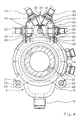
- Fig. 2 einen Querschnitt durch den Gegenstand nach Fig. 1.
- Fig. 3 einen Axialschnitt durch eine weitere Ausführungsform einer Spanneinrichtung nach der Erfindung in einer der Fig. 1 entsprechenden Darstellung, und
- Fig. 4 einen der Fig. 2 entsprechenden Querschnitt durch die Spanneinrichtung nach Fig. 3.
- Der in der Zeichnung dargestellte Spannzylinder 1 für Spanneinrichtungen an Werkzeugmaschinen besitzt ein Zylindergehäuse 3 mit einem darin verschiebbaren Spannkolben 2, der an eine nicht dargestellte Spannstange angeschlossen werden kann. Normalerweise ist das Zylindergehäuse 3 am Ende der nicht dargestellten Werkzeugmaschinenspindel befestigt und läuft einschließlich des Spannkolbens 2 mit dieser um.
- An den Spannzylinder 1 ist ein allgemein mit 4 bezeichneter Verteiler angeschlossen. Dieser Verteiler 4 besitzt ein nicht mit dem Spannzylinder 1 rotierendes Verteilergehäuse 5, das seitlich liegende Anschlüsse 6 für das den Spannzylinder 1 betätigende Arbeitsmedium trägt. Im Verteilergehäuse 5 läuft eine Verteilerwelle 7 um, die mittels Lager 8, 9 im Verteilergehäuse 5 gelagert ist. Das Lager 9 liegt axial an einer Schulter 10 der Verteilerwelle 7, das Lager 8 auf der anderen Seite an einem Sicherungsring 11 an, so daß das Verteilergehäuse 5 auf der Verteilerwelle 7 axial unverrückbar gehalten ist. Die Verteilerwelle 7 ist fest mit dem Spannkolben 2 verbunden und axial verschiebbar in der Wand des Spannzylinders 1 gelagert. Im Ergebnis wird eine Verstellung des Spannkolbens 2 in axialer Richtung unverändert über die Verteilerwelle 7 auf das Verteilergehäuse 5 übertragen.
- Die auf der Innenseite des Verteilergehäuses 5 umlaufenden Ringnuten 12, 13 dienen zur Zu- und Abführung des Arbeitsmediums und stehen mit den Anschlüssen 6 für das Arbeitsmedium in Verbindung. Zwischen der Verteilerwelle 7 und dem Verteilergehäuse 5 durchtretendes Lecköl wird im Kanal 14 gesammelt und durch den Anschluß 15 abgeleitet. Die Verteilerwelle 7 besitzt zwei in den Spannzylinder 1 zu entgegengesetzten Seiten des Spannkolbens 2 führende Wellenkanäle 18, 19, die mit den Ringnuten 12, 13 in Verbindung stehen. Die Steuerung des Arbeitsmediums durch die Wellenkanäle 18, 19 wahlweise zu einer der beiden Seiten des Spannkolbens 2 erfolgt in üblicher Weise und bedarf keiner Beschreibung.
- Zur Wegkontrolle der Axialverschiebungen des Spannkolbens 2 ist eine Kontrolleinrichtung vorgesehen, die aus mehreren Schaltgliedern 20, beispielsweise Berührungsschaltern, und einem Schaltstück 21 zur Betätigung der Schaltglieder 20 besteht. Die Schaltglieder 20 sind mit dem Verteilergehäuse 5 verbunden und nehmen an dessen Axialverschiebungen teil.
- Weiter ist in den Fig. 1 und 2 am Verteilergehäuse 5 in einer Längsführung ein Führungsstab 29 axial verschiebbar geführt, der das Schaltstück 21 trägt. Die axiale Festlegung des Führungsstabs 29 erfolgt am Spannzylinder 1 mit Hilfe eines Ringkugellagers 24. Dazu besitzt der Spannzylinder 1 an seiner dem Verteiler 4 zugewandten Stirnseite einen Ringbund 23, auf dem das zum Spannzylinder 1 koaxiale Ringkugellager 24 angeordnet ist. Es besitzt einen relativ zum Spannzylinder 1 drehbaren und axial unverschiebbaren Lagerring 22. Im einzelnen ist das Lager 24 auf dem Ringbund 23 zwischen einer Ringschulter 25 und einem Sicherungsring 26 angeordnet. Der Lagerring 22 selbst greift axial formschlüssig und radial verschiebbar zwischen zwei Flansche 27, 28, die am Führungsstab 28 an seinem dem Spannzylinder 1 zugekehrten Ende axial mit gegenseitigem freien Abstand nebeneinander angeordnet sind.
- Der Führungsstab 29 ist durch seine Längsführung am Verteilergehäuse 5 gegen drehende Mitnahme durch den Spannzylinder 1 gesichert. Im einzelnen dienen zur Bildung der Längsführung für den Führungsstab 29 zwei am Verteilergehäuse 5 ausgebildete Führungsansätze 33, die den Führungsstab 29 aufnehmende Führungsöffnungen 31 besitzen. Die Führungsöffnungen 31 sind im Querschnitt ebenso wie der Führungsstab 29 selbst kreisrund gestaltet.
- Der dem Lagerring 22 auf der Seite des Spannzylinders 21 anliegende Flansch 27 ist als den Führungsstab 29 begrenzender, mit ihm koaxialer Stirnflansch ausgebildet und fest mit dem Führungsstab verbunden. Der dem Lagerring 22 auf der Seite des Verteilergehäuses 5 anliegende Flansch 28 ist als Ringflansch ausgebildet, der auf dem Führungsstab 29 axial verschiebbar geführt und durch eine Feder 30 gegen den Lagerring 22 angedrückt ist. Der Führungsstab 29 trägt eine die Verschiebung des Flansches 28 gegen die Wirkung der Feder 30 begrenzende Ringschulter 34 und einen in eine Ringnut des Führungsstabs 29 eingelassenen Federring 35, gegen den die als Tellerfeder ausgebildete Feder 30 axial abgestützt ist. Durch diesen federnden Andruck des Flansches 28 ist der Lagerring 22 axial spielfrei mit dem Führungsstab 29 verbunden. Der Lagerring 22 ist gegen Drehung am Führungsstab 29 gesichert, wozu der Führungsstab 29 zwischen den Flanschen 27, 28 einen Stift 36 aufweist, der radial in eine am Lagerring 22 vorgesehene, taschenartig ausgebildete Ausnehmung 37 greift.
- Das Schaltstück 21 ist ein auf dem Führungsstab 29 axial verschiebbarer Schaltring. Er kann mit einer radial im Schaltring geführten Stellschraube 38 auf dem Führungsstab 29 in jeweils gewünschter Position festgestellt werden. Selbstverständlich können auch mehrere Schaltstücke 21 längs des Führungsstabs 29 vorgesehen sein. Zur Aufnahme der Schaltglieder 20 trägt das Verteilergehäuse 5 an seitlichen Flanschflächen 41 eine mit Schrauben 42 befestigte Haube 39, die den Führungsstab 29 von oben her und seitlich übergreift. In der Wand der Haube 39 sind mehrere parallel zur Verstellrichtung des Führungsstabs 29 verlaufende Montageschlitze 40 vorgesehen. Die Schaltglieder 20 sind längs dieser Montageschlitze 40 zwischen den Führungsansätzen 32 verschiebbar und an den Rändern der Montageschlitze 40 mittels Spannmuttern 42 feststellbar. Die Montageschlitze 40 befinden sich jeweils in streifenförmigen ebenen Wandbereichen der Haube 39, wobei diese Wandbereiche jeweils gegeneinander geneigt sind und im Haubenquerschnitt einem Polygonzug folgen. Durch die Neigung dieser streifenförmigen Wandbereiche der Haube 39 ist die Winkelausrichtung der Schaltglieder 20 über den Umfang des Führungsstabs 29 bestimmt. Von der Ausführungsform nach den Fig. 1 und 2 unterscheidet sich die nach den Fig. 3 und 4 im wesentlichen allein darin, daß mehrere Führungsstäbe 29, nämlich insgesamt drei Führungsstäbe, über den Umfang des Verteilergehäuses 5 verteilt angeordnet sind. Für jeden Führungsstab 29 sind zwei eigene Führungsansätze 32 mit Führungsöffnungen 31 vorgesehen. Jeder dieser Führungsstäbe 29 ist an den Lagerring 22 radial verschiebbar angeschlossen und kann als Träger von Schaltstücken 21 dienen, wenn dem Führungsstab entsprechende Hauben 39 als Schaltgliedträger zugeordnet sind. Im Ausführungsbeispiel ist dies aber wie in den Fig. 1 und 2 nur für einen einzigender Führungsstäbe 29 dargestellt.
- Die Fig. 3 und 4 zeigen weiter den Fall ,daß die vom Spannzylinder 1 abgewandten Enden der Führungsstäbe 29 axial über das Verteilgehäuse 5 vorstehen und durch eine Platte 50 verbunden sind, die durch eine zentrale Öffnung und ein Ringfutter 51 als Träger für einen nicht dargestellten Anschlagstab ausgebildet ist. Besitzt - wie in den Ausführungsbeispielen - der Spannzylinder einen freien Durchgang für die Bearbeitung stangenförmiger Werkstücke, so kann der Anschlagstab axial in die hohle Verteilerwelle 7 vorstehen und einen Anschlag für das Werkstück bilden.
- Sind, wie in den Fig. 3 und 4, die Führungsstäbe 29 durch die Platte 50 oder dergl. untereinander starr verbunden, so genügt es auch, nur einen einzigen Führungsstab 29 an den Lagerring 22 anzuschließen, um alle anderen Führungsstäbe 29 gegen Axialverschiebungen zu sichern.
Claims (12)
Priority Applications (3)
| Application Number | Priority Date | Filing Date | Title |
|---|---|---|---|
| AT89119302T ATE94442T1 (de) | 1989-09-01 | 1989-10-18 | Spanneinrichtung an werkzeugmaschinen. |
| BR9001384A BR9001384A (pt) | 1989-09-01 | 1990-03-27 | Conjunto de sujeicao em maquinas-ferramenta |
| JP22231290A JP2864284B2 (ja) | 1989-09-01 | 1990-08-22 | 工作機械のクランプ装置 |
Applications Claiming Priority (2)
| Application Number | Priority Date | Filing Date | Title |
|---|---|---|---|
| DE3929011A DE3929011A1 (de) | 1989-09-01 | 1989-09-01 | Spanneinrichtung an werkzeugmaschinen |
| DE3929011 | 1989-09-01 |
Publications (2)
| Publication Number | Publication Date |
|---|---|
| EP0414958A1 true EP0414958A1 (de) | 1991-03-06 |
| EP0414958B1 EP0414958B1 (de) | 1993-09-15 |
Family
ID=6388394
Family Applications (1)
| Application Number | Title | Priority Date | Filing Date |
|---|---|---|---|
| EP89119302A Expired - Lifetime EP0414958B1 (de) | 1989-09-01 | 1989-10-18 | Spanneinrichtung an Werkzeugmaschinen |
Country Status (4)
| Country | Link |
|---|---|
| US (1) | US4995303A (de) |
| EP (1) | EP0414958B1 (de) |
| DE (2) | DE3929011A1 (de) |
| ES (1) | ES2044015T3 (de) |
Families Citing this family (4)
| Publication number | Priority date | Publication date | Assignee | Title |
|---|---|---|---|---|
| DE4031775A1 (de) * | 1989-11-16 | 1991-05-23 | Roehm Guenter H | Spanneinrichtung an werkzeugmaschinen mit einem umlaufenden spannzylinder |
| US5617034A (en) * | 1995-05-09 | 1997-04-01 | Caterpillar Inc. | Signal improvement in the sensing of hydraulic cylinder piston position using electromagnetic waves |
| DE20012080U1 (de) * | 2000-07-12 | 2000-12-07 | Roehm Gmbh | Komplett-Spannsystem an einer Drehmaschine |
| US20080282878A1 (en) * | 2007-05-16 | 2008-11-20 | Cheng-Chung Chai | Pneumatic rotary actuator |
Citations (2)
| Publication number | Priority date | Publication date | Assignee | Title |
|---|---|---|---|---|
| GB2097707A (en) * | 1981-05-06 | 1982-11-10 | Roehm Guenter H | Clamping device for machine tools |
| EP0082968A1 (de) * | 1981-12-15 | 1983-07-06 | Paul Forkardt GmbH & Co. KG | Vorrichtung zur Einstellung der Schaltpunkte für die Wegkontrolle von umlaufenden Spanneinrichtungen |
Family Cites Families (8)
| Publication number | Priority date | Publication date | Assignee | Title |
|---|---|---|---|---|
| FR2033691A5 (de) * | 1969-03-07 | 1970-12-04 | Roehm Gmbh | |
| US4040338A (en) * | 1976-06-14 | 1977-08-09 | Logansport Machine Co., Inc. | Fluid supply distributor |
| DE2633433C3 (de) * | 1976-07-24 | 1979-03-29 | Goetze Ag, 5093 Burscheid | Vorrichtung zum zentrischen Spannen von ringförmigen Werkstücken |
| FR2396883A1 (fr) * | 1977-07-04 | 1979-02-02 | Precision Industrielle | Dispositif de verin hydraulique annulaire, notamment pour la commande d'un mandrin de serrage de piece sur une machine-outil |
| US4221160A (en) * | 1978-09-26 | 1980-09-09 | Cushman Industries, Incorporated | Fluid operating mechanism for a rotary chuck |
| DE7932853U1 (de) * | 1979-11-21 | 1980-02-21 | Roehm, Guenter Horst, 7927 Sontheim | Umlaufender spannzylinder mit spannkolben fuer spanneinrichtungen an werkzeugmaschinen |
| DE3105872C2 (de) * | 1981-02-18 | 1984-12-06 | Paul Forkardt GmbH & Co KG, 4000 Düsseldorf | Einrichtung zur Bestimmung des Arbeitshubes des Kolbens eines doppeltwirkenden Spannzylinders zur Betätigung von Spanneinrichtungen an Werkzeugmaschinen |
| ATE57117T1 (de) * | 1985-10-23 | 1990-10-15 | Aced Sa | Drehender hydraulikzylinder. |
-
1989
- 1989-09-01 DE DE3929011A patent/DE3929011A1/de not_active Withdrawn
- 1989-10-18 EP EP89119302A patent/EP0414958B1/de not_active Expired - Lifetime
- 1989-10-18 DE DE89119302T patent/DE58905642D1/de not_active Expired - Fee Related
- 1989-10-18 ES ES89119302T patent/ES2044015T3/es not_active Expired - Lifetime
-
1990
- 1990-01-08 US US07/461,987 patent/US4995303A/en not_active Expired - Fee Related
Patent Citations (2)
| Publication number | Priority date | Publication date | Assignee | Title |
|---|---|---|---|---|
| GB2097707A (en) * | 1981-05-06 | 1982-11-10 | Roehm Guenter H | Clamping device for machine tools |
| EP0082968A1 (de) * | 1981-12-15 | 1983-07-06 | Paul Forkardt GmbH & Co. KG | Vorrichtung zur Einstellung der Schaltpunkte für die Wegkontrolle von umlaufenden Spanneinrichtungen |
Also Published As
| Publication number | Publication date |
|---|---|
| US4995303A (en) | 1991-02-26 |
| ES2044015T3 (es) | 1994-01-01 |
| DE3929011A1 (de) | 1991-03-07 |
| DE58905642D1 (de) | 1993-10-21 |
| EP0414958B1 (de) | 1993-09-15 |
Similar Documents
| Publication | Publication Date | Title |
|---|---|---|
| DE2137698C3 (de) | Rundschalttisch mit einem feststehenden Grundkörper und einer darauf dreh- und winkeleinstellbar angeordneten Aufspannplatte | |
| WO2006010607A1 (de) | Wuchtring und verfahren zum auswuchten eines rotierenden bauteils | |
| EP0416610B1 (de) | Werkzeugträgeranordnung, insbesondere für Drehmaschinen, mit auswechselbaren Werkzeughaltern | |
| EP0962280B1 (de) | Ausrichteinrichtung | |
| DE3117850C2 (de) | ||
| EP0259409B1 (de) | Zum nutenfräsen verstellbarer werkzeughalter an werkzeugmaschinen | |
| EP0396876A1 (de) | Revolverschneidpresse mit drehbarem Werkzeug | |
| EP0414958B1 (de) | Spanneinrichtung an Werkzeugmaschinen | |
| EP0226177B1 (de) | Innenzahnradmaschine | |
| DE3502774A1 (de) | Linearantriebseinheit | |
| WO2001043904A1 (de) | Werkzeugantrieb für werkzeugmaschinen | |
| EP0208827A1 (de) | Greifvorrichtung | |
| EP0416611B1 (de) | Anordnung eines auswechselbaren Werkzeughalters an einem Revolverkopf einer Drehmaschine | |
| DE2821635A1 (de) | Hubvorrichtung | |
| DE102010050612B4 (de) | Drehantriebsvorrichtung | |
| DE3049423C2 (de) | Tellermagazin als Werkzeugspeicher einer Universal-Bohr-und Fräsmaschine | |
| EP0496967B1 (de) | Spanneinrichtung an Werkzeugmaschinen mit einem umlaufenden Spannzylinder | |
| EP0185170B1 (de) | Backenspannfutter für Drehmaschinen zur Bearbeitung von Werkstücken unter mehreren Bearbeitungsachsen | |
| EP0523541B1 (de) | Manuell betriebener Rundschalttisch | |
| EP0353384A2 (de) | Spanneinrichtung an Werkzeugmaschinen mit einem umlaufenden Spannzylinder | |
| DE3938099C1 (en) | Clamp on machine tool - incorporates slider mechanism moving on guide bar | |
| WO1982002011A1 (en) | Motor device for the radial displacement of a drilling tool | |
| DE4031775C2 (de) | ||
| DE3325838C1 (de) | Vorrichtung zum Spannen einer Kette | |
| DE3635470A1 (de) | Stichsaege |
Legal Events
| Date | Code | Title | Description |
|---|---|---|---|
| PUAI | Public reference made under article 153(3) epc to a published international application that has entered the european phase |
Free format text: ORIGINAL CODE: 0009012 |
|
| 17P | Request for examination filed |
Effective date: 19901116 |
|
| AK | Designated contracting states |
Kind code of ref document: A1 Designated state(s): AT CH DE ES FR GB IT LI SE |
|
| 17Q | First examination report despatched |
Effective date: 19930225 |
|
| GRAA | (expected) grant |
Free format text: ORIGINAL CODE: 0009210 |
|
| AK | Designated contracting states |
Kind code of ref document: B1 Designated state(s): AT CH DE ES FR GB IT LI SE |
|
| REF | Corresponds to: |
Ref document number: 94442 Country of ref document: AT Date of ref document: 19931015 Kind code of ref document: T |
|
| REF | Corresponds to: |
Ref document number: 58905642 Country of ref document: DE Date of ref document: 19931021 |
|
| ET | Fr: translation filed | ||
| ITF | It: translation for a ep patent filed |
Owner name: STUDIO JAUMANN |
|
| REG | Reference to a national code |
Ref country code: ES Ref legal event code: FG2A Ref document number: 2044015 Country of ref document: ES Kind code of ref document: T3 |
|
| GBT | Gb: translation of ep patent filed (gb section 77(6)(a)/1977) |
Effective date: 19931202 |
|
| PLBE | No opposition filed within time limit |
Free format text: ORIGINAL CODE: 0009261 |
|
| STAA | Information on the status of an ep patent application or granted ep patent |
Free format text: STATUS: NO OPPOSITION FILED WITHIN TIME LIMIT |
|
| 26N | No opposition filed | ||
| EAL | Se: european patent in force in sweden |
Ref document number: 89119302.1 |
|
| PGFP | Annual fee paid to national office [announced via postgrant information from national office to epo] |
Ref country code: SE Payment date: 19950929 Year of fee payment: 7 |
|
| PGFP | Annual fee paid to national office [announced via postgrant information from national office to epo] |
Ref country code: CH Payment date: 19951005 Year of fee payment: 7 |
|
| PGFP | Annual fee paid to national office [announced via postgrant information from national office to epo] |
Ref country code: AT Payment date: 19951031 Year of fee payment: 7 |
|
| PG25 | Lapsed in a contracting state [announced via postgrant information from national office to epo] |
Ref country code: AT Effective date: 19961018 |
|
| PG25 | Lapsed in a contracting state [announced via postgrant information from national office to epo] |
Ref country code: SE Effective date: 19961019 |
|
| PG25 | Lapsed in a contracting state [announced via postgrant information from national office to epo] |
Ref country code: LI Effective date: 19961031 Ref country code: CH Effective date: 19961031 |
|
| REG | Reference to a national code |
Ref country code: CH Ref legal event code: PL |
|
| EUG | Se: european patent has lapsed |
Ref document number: 89119302.1 |
|
| PGFP | Annual fee paid to national office [announced via postgrant information from national office to epo] |
Ref country code: GB Payment date: 19971007 Year of fee payment: 9 Ref country code: FR Payment date: 19971007 Year of fee payment: 9 |
|
| PGFP | Annual fee paid to national office [announced via postgrant information from national office to epo] |
Ref country code: ES Payment date: 19971010 Year of fee payment: 9 |
|
| PGFP | Annual fee paid to national office [announced via postgrant information from national office to epo] |
Ref country code: DE Payment date: 19971211 Year of fee payment: 9 |
|
| PG25 | Lapsed in a contracting state [announced via postgrant information from national office to epo] |
Ref country code: GB Free format text: LAPSE BECAUSE OF NON-PAYMENT OF DUE FEES Effective date: 19981018 |
|
| PG25 | Lapsed in a contracting state [announced via postgrant information from national office to epo] |
Ref country code: ES Free format text: LAPSE BECAUSE OF THE APPLICANT RENOUNCES Effective date: 19981019 |
|
| GBPC | Gb: european patent ceased through non-payment of renewal fee |
Effective date: 19981018 |
|
| PG25 | Lapsed in a contracting state [announced via postgrant information from national office to epo] |
Ref country code: FR Free format text: LAPSE BECAUSE OF NON-PAYMENT OF DUE FEES Effective date: 19990630 |
|
| REG | Reference to a national code |
Ref country code: FR Ref legal event code: ST |
|
| PG25 | Lapsed in a contracting state [announced via postgrant information from national office to epo] |
Ref country code: DE Free format text: LAPSE BECAUSE OF NON-PAYMENT OF DUE FEES Effective date: 19990803 |
|
| REG | Reference to a national code |
Ref country code: ES Ref legal event code: FD2A Effective date: 20001102 |
|
| PG25 | Lapsed in a contracting state [announced via postgrant information from national office to epo] |
Ref country code: IT Free format text: LAPSE BECAUSE OF NON-PAYMENT OF DUE FEES;WARNING: LAPSES OF ITALIAN PATENTS WITH EFFECTIVE DATE BEFORE 2007 MAY HAVE OCCURRED AT ANY TIME BEFORE 2007. THE CORRECT EFFECTIVE DATE MAY BE DIFFERENT FROM THE ONE RECORDED. Effective date: 20051018 |