EP0414929B1 - Appareil médical utilisable au choix en mode bipolaire ou unipolaire, ayant un connecteur pour une électrode conductrice d'un signal électrique entre l'appareil et le corps d'un être vivant - Google Patents
Appareil médical utilisable au choix en mode bipolaire ou unipolaire, ayant un connecteur pour une électrode conductrice d'un signal électrique entre l'appareil et le corps d'un être vivant Download PDFInfo
- Publication number
- EP0414929B1 EP0414929B1 EP89115851A EP89115851A EP0414929B1 EP 0414929 B1 EP0414929 B1 EP 0414929B1 EP 89115851 A EP89115851 A EP 89115851A EP 89115851 A EP89115851 A EP 89115851A EP 0414929 B1 EP0414929 B1 EP 0414929B1
- Authority
- EP
- European Patent Office
- Prior art keywords
- pole
- unipolar
- connection
- electrode
- bipolar
- Prior art date
- Legal status (The legal status is an assumption and is not a legal conclusion. Google has not performed a legal analysis and makes no representation as to the accuracy of the status listed.)
- Expired - Lifetime
Links
Images
Classifications
-
- A—HUMAN NECESSITIES
- A61—MEDICAL OR VETERINARY SCIENCE; HYGIENE
- A61N—ELECTROTHERAPY; MAGNETOTHERAPY; RADIATION THERAPY; ULTRASOUND THERAPY
- A61N1/00—Electrotherapy; Circuits therefor
- A61N1/18—Applying electric currents by contact electrodes
- A61N1/32—Applying electric currents by contact electrodes alternating or intermittent currents
- A61N1/36—Applying electric currents by contact electrodes alternating or intermittent currents for stimulation
- A61N1/372—Arrangements in connection with the implantation of stimulators
- A61N1/375—Constructional arrangements, e.g. casings
- A61N1/3752—Details of casing-lead connections
Definitions
- the invention relates to a medical device according to the preamble of claim 1, to which either a bipolar or a unipolar electrode for conducting electrical signals between the device and the body of a living being can be connected and which has a signal potential and a connection carrying a reference potential, wherein the device can be switched to either bipolar or unipolar operation and, in the case of unipolar operation, the connection carrying the reference potential is conductively connected to means for applying the reference potential to the body of the living being.
- the procedure is such that a region of the body of the living being suitable for supplying or discharging the respective electrical signals is connected to the connection carrying the signal potential by means of the unipolar electrode, while the reference potential is connected to another point on the Body of the living being is created with the aid of the means for applying the reference potential.
- a unipolar electrode therefore usually has only one conductor. If a bipolar electrode is used, both the connection which carries the signal potential and the reference potential are connected to an area of the body which is suitable for supplying or removing the respective electrical signals and for applying the reference potential by means of the bipolar electrode.
- a bipolar electrode therefore has two lines which end in relatively closely spaced contact parts intended for contacting the essentially the same area of the body of the living being.
- a device of the type mentioned at the outset is known which is designed as a pacemaker.
- This device thus has means for stimulating the heart activity of a living being and means for detecting heartbeats, wherein the means for stimulating stimulation impulses are directed to the heart of the living being by means of an electrode, while signals corresponding to the electrical activity of the heart are sent via an electrode to the heart Means for detection are directed.
- the known pacemaker is a device that can be implanted in the body of the living being, to which either a unipolar or a bipolar endocardial electrode can be connected, which lead through the patient's venous system into the corresponding atrium or ventricle of the heart and is anchored there.
- bipolar electrode Since it may be necessary to switch from bipolar to unipolar operation and vice versa even after implantation of the device, the corresponding switchover can be carried out telemetrically with the help of an external device, a so-called programmer. It goes without saying that a bipolar electrode must be connected to the pacemaker as an essential prerequisite for the transition from unipolar to bipolar operation.
- a transition from bipolar to unipolar stimulation can e.g. be expedient because in most patients the amount of energy required to achieve stimulation is less with unipolar stimulation.
- a transition from unipolar to bipolar stimulation is indicated if, in the area in which the reference potential is applied to the body of the living being, in the case of a pacemaker, normally in the area of its electrically conductive connection and with the connection of the device carrying the reference potential Conductively connected housing, unwanted stimulation effects, eg Muscle twitches occur.
- a transition from unipolar to bipolar detection can be useful if strong interference (noise) occurs with unipolar detection. Such disturbances usually occur less strongly with bipolar detection.
- the invention is therefore based on the object of designing a device of the type mentioned at the outset in such a way that errors in the type of the connected electrode remain without consequences for the patient when switching from unipolar to bipolar operation.
- a device is already known from US-A-4,532,931 which is designed as a pacemaker with unipolar stimulation and automatic switching between unipolar and bipolar detection.
- the automatic (ie without the doctor's intervention) switching between the types of detection is achieved in that a first and a second impedance, each much greater than the impedance of the body tissue and significantly lower than the impedance of the input amplifier, the first and the second impedance between the pacemaker capsule and the reference potential connection for the ring electrode or between the pacemaker housing and the Signal potential connection for the tip electrode are connected, and which, depending on whether a bipolar or a unipolar electrode is connected to the device, determine the signal that reaches the amplifier. If no bipolar electrode is connected to this device, the second impedance creates an electrically conductive connection between the reference potential connection and the housing. This conductive connection is therefore also present with unipolar detection, but without the connection being established in the first place.
- this object is achieved in that a conductive connection of the connection carrying the reference potential to the means for applying the reference potential is not established until a unipolar electrode is connected to the device.
- the measure according to the invention ensures that even if a unipolar electrode is connected to the device and, on the erroneous assumption that it is a bipolar electrode, it is switched over to bipolar operation, a conductive connection between the connection carrying the reference potential and the means for applying the reference potential is present. Malfunctions and possible adverse consequences for the patient are thus avoided with certainty.
- the invention provides that the device has electrical connection means for the optional connection of the bipolar or unipolar electrode and that the electrical connection means are designed such that only when the unipolar electrode is connected does the conductive connection of the connection carrying the reference potential to the means for applying necessarily of the reference potential is established.
- electrical connection means that are required are formed in such a way that the desired conductive connection is inevitable when a unipolar electrode is connected, so that the required technical outlay is extremely low.
- the electrical connection means can preferably be designed as a plug connection. Accordingly, a plug connection which enables a convenient and simple connection of the respective electrode is designed in such a way that when a unipolar electrode is connected, the desired conductive connection between the connection of the device carrying the reference potential and the means for applying the reference potential is inevitable. It can be provided according to a variant of the invention that the means for establishing a conductive connection can be formed by a contact section attached to the second connection part assigned to the unipolar electrode.
- the plug connection can then be designed in a technically simple and cost-effective manner as a coaxial rotationally symmetrical plug connection, the poles of the first connecting part assigned to the device being arranged axially in succession and the second and third poles being adjacent to one another.
- the device can be implanted in the body of the living being and can be switched telemetrically to unipolar or bipolar operation.
- it is particularly difficult to determine after the implantation of the device whether a bipolar electrode is actually connected, so that an erroneous switchover to bipolar operation is particularly easy and the avoidance of negative consequences for the patient is therefore particularly important.
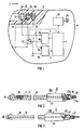
- the pacemaker according to the invention which is intended for implantation in the body of a living being, has a stimulation pulse generator (1) and a detector circuit (2), each of which is connected to a control logic (3).
- the control logic (3) causes the stimulation pulse generator (1) to emit an electrical stimulation pulse whenever a natural heartbeat detected by means of the detector circuit (2) or a stimulation pulse emitted by the stimulation pulse generator (1) after a time corresponding to a certain heart rate intervals no natural heartbeat was detected by means of the detector circuit (2).
- the stimulation pulse generator (1) has an output (4a) carrying the stimulation potential and an output connection (4b) carrying a reference potential.
- the detector circuit (2) has an input (5a) at which the potential corresponding to the electrical activity of the heart to be stimulated is present and an input connection (5b) which carries the reference potential.
- the pacemaker thus has a connection (6) which carries the signal potential, which is formed by the connection point of the output (4a) of the stimulation pulse generator (1) to the input (5a) of the detector circuit (2), and a connection which carries the reference potential ( 7), which is formed by the connection point of the output connection (4b) of the stimulation pulse generator (1) to the input connection (5b) of the detector circuit (2).
- connection (6) is therefore connected to the first pole (21) of a plug connection serving to connect both bipolar and unipolar electrodes, of which only the first connection part (8) assigned to the pacemaker is shown in FIG.
- the reference potential is applied directly to the heart via the bipolar electrode.
- the first connecting part (8) therefore has a second pole (23) which can be connected by means of a switch (22) designed as an electronic switch to the connection (7) of the pacemaker carrying the reference potential.
- the corresponding switch position of the switch (22) is shown in FIG. 1.
- a unipolar electrode is used, the reference potential is established via a hermetically sealed housing (9) which surrounds the electronic components of the pacemaker and is schematically indicated in FIG. 1 and which is made of an electrically conductive material, e.g. Titanium, formed, is applied to the body of the living being. This is done by moving the changeover switch (22) to its switching position (not shown in FIG. 1), in which there is a conductive connection between the connection (7) of the pacemaker that carries the reference potential and the housing (9).
- the first connection part (8) of the plug connection assigned to the pacemaker is attached to the housing (9).
- the line (11) has a central conductor (13) and an outer conductor (14), for example a metal braid, which surrounds the central conductor (13) and is electrically insulated from it.
- the outer conductor (14) is also insulated.
- the central conductor (13) is electrically conductively connected to a tip (15) which is brought into contact with the tissue of the heart to be stimulated.
- the center conductor (13) is used to supply the heart with stimulation pulses or the pacemaker with signals corresponding to the electrical activity of the heart.
- the outer conductor (14) is electrically conductively connected to a ring (16), which is also brought into contact with the tissue of the heart and serves to place the heart at the reference potential.
- the unipolar electrode (17) shown in FIG. 3 is constructed accordingly, but here the outer conductor (14) and the ring (16) are missing.
- the unipolar electrode (17) thus has a single-pole line (18) with a conductor (19) which ends in the tip (20) and, like the center conductor (13) of the bipolar electrode (10), for conducting the stimulation pulses and that of the electrical ones Activity of the heart corresponding signals and a second connecting part (12b).
- the unipolar electrode (17) is used, the reference potential is not applied directly to the heart to be stimulated, but via the electrically conductive housing (9) (see FIG. 1) of the pacemaker to the body of the living being.
- the second connecting parts (12a and 12b) each have a first pole (21a or 21b) corresponding to the first pole (21) of the first connecting part (8), via which, when the electrode ( 10 or 17) of the center conductor (13) or the conductor (19) is connected to the connection (6) of the pacemaker which carries the signal potential.
- the second connecting part (12a) assigned to the bipolar electrode (10) also has the second pole (23a) corresponding to the second pole (23) of the first connecting part (8), to which the ring (16) is connected in an electrically conductive manner via the outer conductor (14).
- the switching position of the changeover switch (22) shown in FIG. 1 corresponds to the bipolar operating mode, as can be seen from the above explanation, while the switching position (not shown) corresponds to the unipolar operating mode.
- the switch position (not shown) must be assumed by the changeover switch (22) even when the unipolar electrode (17) is connected to the pacemaker, since otherwise due to the lack of a connection between the terminal (7) carrying the reference potential and the body of the Living pacemaker-carrying organisms would malfunction.
- the pacemaker shown in FIG. 1 has a telemetry circuit (25) which is connected to a transmit / receive coil (24) and is connected to the control logic (3).
- an external device not shown, which also has a transmit / receive coil, there is the possibility, even after the implantation of the pacemaker, to carry out a data exchange between the pacemaker and the external device, provided the external device is relative to the body of the pacemaker supporting living being is brought into such a position that there is an inductive coupling of the transmit / receive coil of the external device with the transmit / receive coil (24) of the pacemaker.
- the possibility of actuating the changeover switch (22) telemetrically which is indicated by a control line provided between the changeover switch (22) and the control logic (3) in order to be able to switch the pacemaker from bipolar to unipolar operation and vice versa.
- the first connecting part (8) has a third pole (26) which is permanently connected in an electrically conductive manner to the housing (9) of the pacemaker, while the second connecting part (12b) the unipolar electrode (17) has a contact section (27) which is designed such that, when the unipolar electrode (17) is connected, it has an electrically conductive connection between the third pole (26) and the second pole (23) of the first connecting part (8 ) produces.
- the unipolar electrode (17) when the unipolar electrode (17) is connected, there is an electrically conductive connection between the connection (7) of the pacemaker, which carries the reference potential, on the one hand, and the housing (9) of the pacemaker, on the other, regardless of the switching position of the switch (22). Malfunctions can therefore not occur if the pacemaker is accidentally switched to bipolar operation when the unipolar electrode (17) is connected.
- the connector is designed as a coaxial rotationally symmetrical connector.
- the poles of the first connecting part (8) are formed by three annular contact parts (28, 29, 30) arranged axially at a distance from one another. These are embedded in a carrier part (31) made of an electrically insulating material, which has a bore for receiving the second connecting part (12a or 12b) associated with the bipolar electrode (10) or the unipolar electrode (17). Bore walls of the contact parts (28, 29, 30), which represent their contact surfaces and are therefore exposed, form wall sections of the bore (32). The bore diameters of the contact parts (28, 29, 30) decrease in the direction of insertion indicated by an arrow x.
- the contact part (28) forms the first pole, the contact part (29) the second pole and the contact part (30) the third pole of the first connecting part (8).
- the second connecting parts (12a and 12b) each have a base body (33 or 34) formed from an electrically insulating material.
- the base bodies (33, 34) are shaped such that they can be inserted into the bore (32) of the first connecting part (8).
- the connecting part (12a) belonging to the bipolar electrode (10) its two poles are formed by two ring-shaped contact parts (35 and 36), which are arranged and dimensioned in such a way that they with their cylindrical outer surfaces, which form the contact surfaces, and consequently are exposed, contact the contact surfaces of the contact parts (28 and 29) of the first connecting part when the second connecting part (12a) is inserted into the first connecting part (8).
- the only pole of the connecting part (12b) assigned to the unipolar electrode (17) is formed by a contact part (37) which corresponds to the contact part (35) in terms of its dimensions and arrangement.
- the second connecting part (12b) also has the contact section (27), which is arranged and shaped in such a way that it is inserted into the first connecting part (8) leads the second connecting part (12b) cooperates with the contact parts (29 and 30) so that there is a conductive connection between the two.
Claims (8)
Priority Applications (4)
| Application Number | Priority Date | Filing Date | Title |
|---|---|---|---|
| EP89115851A EP0414929B2 (fr) | 1989-08-28 | 1989-08-28 | Appareil médical utilisable au choix en mode bipolaire ou unipolaire, ayant un connecteur pour une électrode conductrice d'un signal électrique entre l'appareil et le corps d'un être vivant |
| DE58909120T DE58909120D1 (de) | 1989-08-28 | 1989-08-28 | Wahlweise bipolar oder unipolar betreibbares medizinisches Gerät mit einem Anschluss für eine elektrische Signale zwischen dem Gerät und dem Körper eines Lebewesens leitende Elektrode. |
| US07/572,416 US5095902A (en) | 1989-08-28 | 1990-08-27 | Implantable medical stimulation system optionally operable in a bipolar or a unipolar mode |
| JP2224547A JPH0399676A (ja) | 1989-08-28 | 1990-08-28 | 医用装置 |
Applications Claiming Priority (1)
| Application Number | Priority Date | Filing Date | Title |
|---|---|---|---|
| EP89115851A EP0414929B2 (fr) | 1989-08-28 | 1989-08-28 | Appareil médical utilisable au choix en mode bipolaire ou unipolaire, ayant un connecteur pour une électrode conductrice d'un signal électrique entre l'appareil et le corps d'un être vivant |
Publications (3)
| Publication Number | Publication Date |
|---|---|
| EP0414929A1 EP0414929A1 (fr) | 1991-03-06 |
| EP0414929B1 true EP0414929B1 (fr) | 1995-03-15 |
| EP0414929B2 EP0414929B2 (fr) | 1999-12-22 |
Family
ID=8201810
Family Applications (1)
| Application Number | Title | Priority Date | Filing Date |
|---|---|---|---|
| EP89115851A Expired - Lifetime EP0414929B2 (fr) | 1989-08-28 | 1989-08-28 | Appareil médical utilisable au choix en mode bipolaire ou unipolaire, ayant un connecteur pour une électrode conductrice d'un signal électrique entre l'appareil et le corps d'un être vivant |
Country Status (4)
| Country | Link |
|---|---|
| US (1) | US5095902A (fr) |
| EP (1) | EP0414929B2 (fr) |
| JP (1) | JPH0399676A (fr) |
| DE (1) | DE58909120D1 (fr) |
Families Citing this family (11)
| Publication number | Priority date | Publication date | Assignee | Title |
|---|---|---|---|---|
| US5197468A (en) * | 1990-02-13 | 1993-03-30 | Proctor Paul W | Device for protecting an electronic prosthesis from adverse effects of RF and/or electrostatic energy |
| US5374279A (en) * | 1992-10-30 | 1994-12-20 | Medtronic, Inc. | Switchable connector block for implantable defibrillator |
| JP3312531B2 (ja) * | 1994-07-18 | 2002-08-12 | 日本精工株式会社 | 回転速度検出装置付ハブユニット |
| US6003375A (en) * | 1994-07-18 | 1999-12-21 | Nsk Ltd. | Hub unit with rotation speed sensor |
| JP3189624B2 (ja) * | 1994-08-11 | 2001-07-16 | 日本精工株式会社 | 回転速度検出装置付転がり軸受ユニット |
| JPH08200355A (ja) | 1995-01-23 | 1996-08-06 | Nippon Seiko Kk | 回転速度検出装置付転がり軸受ユニット |
| US6892092B2 (en) * | 2001-10-29 | 2005-05-10 | Cardiac Pacemakers, Inc. | Cardiac rhythm management system with noise detector utilizing a hysteresis providing threshold |
| US7062329B2 (en) * | 2002-10-04 | 2006-06-13 | Cameron Health, Inc. | Implantable cardiac system with a selectable active housing |
| US20070265662A1 (en) * | 2006-04-27 | 2007-11-15 | Ufford Keith A | Implantable electromagnetic interference tolerant, wired sensors and methods for implementing same |
| US10339081B2 (en) | 2015-05-09 | 2019-07-02 | Medtronic, Inc. | Methods and devices that utilize hardware to move blocks of operating parameter data from memory to a register set |
| US11216370B2 (en) | 2018-02-20 | 2022-01-04 | Medtronic, Inc. | Methods and devices that utilize hardware to move blocks of operating parameter data from memory to a register set |
Family Cites Families (6)
| Publication number | Priority date | Publication date | Assignee | Title |
|---|---|---|---|---|
| US4236525A (en) * | 1978-11-22 | 1980-12-02 | Intermedics, Inc. | Multiple function lead assembly |
| US4301805A (en) * | 1980-07-30 | 1981-11-24 | Cordis Corporation | Cardiac pacer connector system |
| JPS5736790A (fr) * | 1980-08-13 | 1982-02-27 | Olympus Optical Co | |
| US4558702A (en) * | 1983-01-21 | 1985-12-17 | Cordis Corporation | Cardiac pacer having input/output circuit programmable for use with unipolar and bipolar pacer leads |
| US4532931A (en) * | 1984-06-29 | 1985-08-06 | Cardiac Pacemakers, Inc. | Pacemaker with adaptive sensing means for use with unipolar or bipolar leads |
| US4741342A (en) * | 1986-03-11 | 1988-05-03 | Intermedics, Inc. | Cardiac pacemaker with selective unipolar/bipolar pacing |
-
1989
- 1989-08-28 DE DE58909120T patent/DE58909120D1/de not_active Expired - Fee Related
- 1989-08-28 EP EP89115851A patent/EP0414929B2/fr not_active Expired - Lifetime
-
1990
- 1990-08-27 US US07/572,416 patent/US5095902A/en not_active Expired - Lifetime
- 1990-08-28 JP JP2224547A patent/JPH0399676A/ja active Pending
Also Published As
| Publication number | Publication date |
|---|---|
| EP0414929A1 (fr) | 1991-03-06 |
| JPH0399676A (ja) | 1991-04-24 |
| US5095902A (en) | 1992-03-17 |
| EP0414929B2 (fr) | 1999-12-22 |
| DE58909120D1 (de) | 1995-04-20 |
Similar Documents
| Publication | Publication Date | Title |
|---|---|---|
| DE602004009585T2 (de) | Verbindungsstücke zur verbindung einer leitung mit einem implantierbaren medizinischen gerät | |
| EP1062969B1 (fr) | Ensemble électrode | |
| DE69824258T2 (de) | Herzschrittmacherleitung mit poröser Elektrode | |
| EP1062970B1 (fr) | Ensemble électrode | |
| DE60303244T2 (de) | Implantierbare Herzstimulationsvorrichtung und System, das diese Vorrichtung umfasst | |
| EP0559932A1 (fr) | Ensemble implantable pour la défibrillation ou la cardioversion d'un coeur | |
| DE4231600B4 (de) | Implantierbares Defibrillationssystem | |
| EP0414929B1 (fr) | Appareil médical utilisable au choix en mode bipolaire ou unipolaire, ayant un connecteur pour une électrode conductrice d'un signal électrique entre l'appareil et le corps d'un être vivant | |
| EP0559933A1 (fr) | Configuration d'électrodes pour un défibrillateur/cardioverteur implantable | |
| DE2358883A1 (de) | Einadrige kathetervorrichtung und schrittmachverfahren | |
| DE2218981A1 (de) | Funktionssteuerschalter fur Korper organ Stimulator | |
| EP3278836B1 (fr) | Implant électromédical comprenant un passage électrique | |
| EP3284516B1 (fr) | Implant et procédé d'identification d'une ligne d'électrodes | |
| DE602005006364T2 (de) | Stimulations-Lead-Elektrode mit automatischem Capturing | |
| EP0813886B1 (fr) | Système d'électrodes de défibrillation | |
| DE3914677C2 (fr) | ||
| EP0490985B1 (fr) | Appareil medical pour stimuler les contractions tissulaires | |
| DE3248009A1 (de) | Schrittmach/abtast-herzschrittmacher mit drei elektroden | |
| EP3332836B1 (fr) | Traversée d'un appareil médical électronique implantable | |
| EP3284510B1 (fr) | Ligne d'electrodes, implant et procede d'identification d'une ligne d'electrodes | |
| DE10302319B4 (de) | Bipolare Stimulationselektrode | |
| DE3722829C2 (de) | Verfahren und Anordnung zur Steuerung der Impulsabgabe eines implantierbaren elektromedizinischen Gerätes | |
| EP0306443B1 (fr) | Prise coaxiale pour stimulateur cardiaque | |
| EP2465569A2 (fr) | Appareil implantable | |
| EP2465570B1 (fr) | Appareil implantable |
Legal Events
| Date | Code | Title | Description |
|---|---|---|---|
| PUAI | Public reference made under article 153(3) epc to a published international application that has entered the european phase |
Free format text: ORIGINAL CODE: 0009012 |
|
| 17P | Request for examination filed |
Effective date: 19901205 |
|
| AK | Designated contracting states |
Kind code of ref document: A1 Designated state(s): DE FR GB IT NL SE |
|
| 17Q | First examination report despatched |
Effective date: 19930422 |
|
| RAP1 | Party data changed (applicant data changed or rights of an application transferred) |
Owner name: PACESETTER AB |
|
| GRAA | (expected) grant |
Free format text: ORIGINAL CODE: 0009210 |
|
| AK | Designated contracting states |
Kind code of ref document: B1 Designated state(s): DE FR GB IT NL SE |
|
| PG25 | Lapsed in a contracting state [announced via postgrant information from national office to epo] |
Ref country code: NL Free format text: LAPSE BECAUSE OF FAILURE TO SUBMIT A TRANSLATION OF THE DESCRIPTION OR TO PAY THE FEE WITHIN THE PRESCRIBED TIME-LIMIT Effective date: 19950315 |
|
| REF | Corresponds to: |
Ref document number: 58909120 Country of ref document: DE Date of ref document: 19950420 |
|
| ET | Fr: translation filed | ||
| ITF | It: translation for a ep patent filed |
Owner name: STUDIO JAUMANN |
|
| PG25 | Lapsed in a contracting state [announced via postgrant information from national office to epo] |
Ref country code: SE Effective date: 19950615 |
|
| GBT | Gb: translation of ep patent filed (gb section 77(6)(a)/1977) |
Effective date: 19950608 |
|
| PLBQ | Unpublished change to opponent data |
Free format text: ORIGINAL CODE: EPIDOS OPPO |
|
| PLBI | Opposition filed |
Free format text: ORIGINAL CODE: 0009260 |
|
| PLBF | Reply of patent proprietor to notice(s) of opposition |
Free format text: ORIGINAL CODE: EPIDOS OBSO |
|
| 26 | Opposition filed |
Opponent name: BIOTRONIK MESS- UND THERAPIEGERAETE GMBH & CO INGE Effective date: 19951213 |
|
| NLR1 | Nl: opposition has been filed with the epo |
Opponent name: BIOTRONIK MESS- UND THERAPIEGERAETE GMBH & CO INGE |
|
| PLBF | Reply of patent proprietor to notice(s) of opposition |
Free format text: ORIGINAL CODE: EPIDOS OBSO |
|
| PLBF | Reply of patent proprietor to notice(s) of opposition |
Free format text: ORIGINAL CODE: EPIDOS OBSO |
|
| RAP2 | Party data changed (patent owner data changed or rights of a patent transferred) |
Owner name: PACESETTER AB |
|
| NLT2 | Nl: modifications (of names), taken from the european patent patent bulletin |
Owner name: PACESETTER AB |
|
| PGFP | Annual fee paid to national office [announced via postgrant information from national office to epo] |
Ref country code: GB Payment date: 19980710 Year of fee payment: 10 |
|
| PLBQ | Unpublished change to opponent data |
Free format text: ORIGINAL CODE: EPIDOS OPPO |
|
| PLAB | Opposition data, opponent's data or that of the opponent's representative modified |
Free format text: ORIGINAL CODE: 0009299OPPO |
|
| PLAW | Interlocutory decision in opposition |
Free format text: ORIGINAL CODE: EPIDOS IDOP |
|
| R26 | Opposition filed (corrected) |
Opponent name: BIOTRONIK MESS- UND THERAPIEGERAETE GMBH & CO INGE Effective date: 19951213 |
|
| NLR1 | Nl: opposition has been filed with the epo |
Opponent name: BIOTRONIK MESS- UND THERAPIEGERAETE GMBH & CO INGE |
|
| PLAW | Interlocutory decision in opposition |
Free format text: ORIGINAL CODE: EPIDOS IDOP |
|
| PG25 | Lapsed in a contracting state [announced via postgrant information from national office to epo] |
Ref country code: GB Free format text: LAPSE BECAUSE OF NON-PAYMENT OF DUE FEES Effective date: 19990828 |
|
| PGFP | Annual fee paid to national office [announced via postgrant information from national office to epo] |
Ref country code: NL Payment date: 19990830 Year of fee payment: 11 |
|
| PUAH | Patent maintained in amended form |
Free format text: ORIGINAL CODE: 0009272 |
|
| STAA | Information on the status of an ep patent application or granted ep patent |
Free format text: STATUS: PATENT MAINTAINED AS AMENDED |
|
| 27A | Patent maintained in amended form |
Effective date: 19991222 |
|
| AK | Designated contracting states |
Kind code of ref document: B2 Designated state(s): DE FR GB IT NL SE |
|
| NLR2 | Nl: decision of opposition | ||
| ITF | It: translation for a ep patent filed |
Owner name: STUDIO JAUMANN P. & C. S.N.C. |
|
| ET3 | Fr: translation filed ** decision concerning opposition | ||
| GBPC | Gb: european patent ceased through non-payment of renewal fee |
Effective date: 19990828 |
|
| NLV1 | Nl: lapsed or annulled due to failure to fulfill the requirements of art. 29p and 29m of the patents act | ||
| PGFP | Annual fee paid to national office [announced via postgrant information from national office to epo] |
Ref country code: FR Payment date: 20060731 Year of fee payment: 18 |
|
| PGFP | Annual fee paid to national office [announced via postgrant information from national office to epo] |
Ref country code: IT Payment date: 20060831 Year of fee payment: 18 |
|
| PGFP | Annual fee paid to national office [announced via postgrant information from national office to epo] |
Ref country code: DE Payment date: 20060901 Year of fee payment: 18 |
|
| REG | Reference to a national code |
Ref country code: FR Ref legal event code: ST Effective date: 20080430 |
|
| PG25 | Lapsed in a contracting state [announced via postgrant information from national office to epo] |
Ref country code: DE Free format text: LAPSE BECAUSE OF NON-PAYMENT OF DUE FEES Effective date: 20080301 |
|
| PG25 | Lapsed in a contracting state [announced via postgrant information from national office to epo] |
Ref country code: FR Free format text: LAPSE BECAUSE OF NON-PAYMENT OF DUE FEES Effective date: 20070831 |
|
| PG25 | Lapsed in a contracting state [announced via postgrant information from national office to epo] |
Ref country code: IT Free format text: LAPSE BECAUSE OF NON-PAYMENT OF DUE FEES Effective date: 20070828 |