EP0414697B1 - Einwärts schwingende drehbare türvorrichtung - Google Patents
Einwärts schwingende drehbare türvorrichtung Download PDFInfo
- Publication number
- EP0414697B1 EP0414697B1 EP19890903929 EP89903929A EP0414697B1 EP 0414697 B1 EP0414697 B1 EP 0414697B1 EP 19890903929 EP19890903929 EP 19890903929 EP 89903929 A EP89903929 A EP 89903929A EP 0414697 B1 EP0414697 B1 EP 0414697B1
- Authority
- EP
- European Patent Office
- Prior art keywords
- door assembly
- door
- weatherstrip
- cooperatively connected
- frame
- Prior art date
- Legal status (The legal status is an assumption and is not a legal conclusion. Google has not performed a legal analysis and makes no representation as to the accuracy of the status listed.)
- Expired - Lifetime
Links
Images


Classifications
-
- E—FIXED CONSTRUCTIONS
- E06—DOORS, WINDOWS, SHUTTERS, OR ROLLER BLINDS IN GENERAL; LADDERS
- E06B—FIXED OR MOVABLE CLOSURES FOR OPENINGS IN BUILDINGS, VEHICLES, FENCES OR LIKE ENCLOSURES IN GENERAL, e.g. DOORS, WINDOWS, BLINDS, GATES
- E06B7/00—Special arrangements or measures in connection with doors or windows
- E06B7/16—Sealing arrangements on wings or parts co-operating with the wings
-
- E—FIXED CONSTRUCTIONS
- E06—DOORS, WINDOWS, SHUTTERS, OR ROLLER BLINDS IN GENERAL; LADDERS
- E06B—FIXED OR MOVABLE CLOSURES FOR OPENINGS IN BUILDINGS, VEHICLES, FENCES OR LIKE ENCLOSURES IN GENERAL, e.g. DOORS, WINDOWS, BLINDS, GATES
- E06B1/00—Border constructions of openings in walls, floors, or ceilings; Frames to be rigidly mounted in such openings
- E06B1/04—Frames for doors, windows, or the like to be fixed in openings
- E06B1/32—Frames composed of parts made of different materials
-
- E—FIXED CONSTRUCTIONS
- E06—DOORS, WINDOWS, SHUTTERS, OR ROLLER BLINDS IN GENERAL; LADDERS
- E06B—FIXED OR MOVABLE CLOSURES FOR OPENINGS IN BUILDINGS, VEHICLES, FENCES OR LIKE ENCLOSURES IN GENERAL, e.g. DOORS, WINDOWS, BLINDS, GATES
- E06B1/00—Border constructions of openings in walls, floors, or ceilings; Frames to be rigidly mounted in such openings
- E06B1/70—Sills; Thresholds
-
- E—FIXED CONSTRUCTIONS
- E06—DOORS, WINDOWS, SHUTTERS, OR ROLLER BLINDS IN GENERAL; LADDERS
- E06B—FIXED OR MOVABLE CLOSURES FOR OPENINGS IN BUILDINGS, VEHICLES, FENCES OR LIKE ENCLOSURES IN GENERAL, e.g. DOORS, WINDOWS, BLINDS, GATES
- E06B7/00—Special arrangements or measures in connection with doors or windows
- E06B7/14—Measures for draining-off condensed water or water leaking-in frame members for draining off condensation water, throats at the bottom of a sash
-
- E—FIXED CONSTRUCTIONS
- E06—DOORS, WINDOWS, SHUTTERS, OR ROLLER BLINDS IN GENERAL; LADDERS
- E06B—FIXED OR MOVABLE CLOSURES FOR OPENINGS IN BUILDINGS, VEHICLES, FENCES OR LIKE ENCLOSURES IN GENERAL, e.g. DOORS, WINDOWS, BLINDS, GATES
- E06B7/00—Special arrangements or measures in connection with doors or windows
- E06B7/16—Sealing arrangements on wings or parts co-operating with the wings
- E06B7/22—Sealing arrangements on wings or parts co-operating with the wings by means of elastic edgings, e.g. elastic rubber tubes; by means of resilient edgings, e.g. felt or plush strips, resilient metal strips
- E06B7/23—Plastic, sponge rubber, or like strips or tubes
- E06B7/2305—Plastic, sponge rubber, or like strips or tubes with an integrally formed part for fixing the edging
Definitions
- This invention relates generally to an inwardly swinging door and more specifically to an inwardly swinging door that is constructed using a multi-point lock, weatherstripping in one plane and a pressure equalization member to provide for an improved weatherproof door.
- Most doors utilize a single point lock.
- a single point lock When a single point lock is utilized, the door is cooperatively connected to the frame of the door only by means of the hinges and the single point lock.
- the hinges are typically multi-point and connect the door to the frame at the top, middle and bottom of the door.
- the multi-point connection helps in the preventing of bowing and hence leakage along the section that is open.
- bowing of the top and bottom of the door itself is more prevalent.
- multi-point locks have been utilized for doors. However, these locks have most often been incorporated into doors for increased security. For example, U.S.-A.-4,548,342 discloses such a lock and is hereby incorporated by reference.
- the prior art doors have been of a "sweep type" design. That is, the weatherstripping on the bottom of the door extended downward and generally came in contact with the threshold. Still further, no pressure equalization chambers were utilized to aid in the prevention of water seeping through the door. Such pressure equalization chambers are in existence for windows. However, the windows are generally outwardly swinging and also the designer of windows is not concerned with stepping up and over threshold as is the designer of doors.
- the National Wood Window and Door Association is developing a standard for wood swinging patio doors. As part of the standard with respect to air infiltration, the Association requires that the unit shall be tested for air leakage in accordance with the latest revision of ASTM E-283 "Standard test method for air leakage through exterior windows, curtain, walls and doors.” Air infiltration shall not exceed 0.10 cubic metres per minute per square metre (0.34 cubic feet per minute per square foot) overall area when tested at a uniform static air pressure difference of 74.7 Pa (1.56 pounds per square feet).
- the water penetration resistance in test standard is that the unit shall be tested for water penetration resistance in accordance with ASTM E-547 "Standard test method for penetration of exterior windows, curtain walls and doors by cyclic air pressure differential."
- the unit shall be tested under a static pressure difference of 137 Pa (2.86 PSF).
- a minimum of three cycles of no less than 5 minutes each shall be used during the test.
- no water shall have passed beyond the interior face of the door unit and overflowed into the room or flowed into the wall area.
- the present invention is able to well surpass these standards and in fact air infiltration does not exceed 0.06 cubic metres per minute per square metre (0.20 cubic feet per minute) and the water penetration can be tested under a static air pressure difference of up to 299 Pa (6.24 PSF).
- the present invention will take a 2874 Pa (60 PSF) positive/negative load using ASTM E-330 with no breakage or unit failure after loads are removed. Residual deflection is less than 0.4% of its span.
- US-A-4 716 683 discloses a door weatherstripping assembly including a first compressible weatherstripping member mounted on and extending continuously around a door with a compressive bulbous body for compressive sealing engagement between the door and the stop member of the door frame upon closure of the door within the frame.
- a second flexible weatherstripping member is mounted on and extends around the door forwardly of the first weatherstripping member for providing a rain screen effect upon closure of the door within the frame.
- the present invention addresses the problems associated with the prior art and provides for an improved door having increased resistance to air infiltration and water penetration and having better structural characteristics.
- the present invention provides an inwardly swinging door assembly for mounting in a frame, the door assembly comprising:
- the weatherstrips are all in a single plane and the weatherstrip is cooperatively connected at intersections of the surfaces, whereby a continuous weatherstrip is formed around the door member.
- Fig. 1 is a front plan view of the door assembly embodying the present invention.
- Fig. 2a is a cross sectional area of the door assembly of Fig. 1, taken generally along the line Fig. 2a-2a.
- Fig. 2b is a cross sectional view of the assembly of Fig. 1, taken generally along the lines 2b-2b.
- Fig. 2c is a cross sectional view of the assembly of Fig. 1, taken generally along the lines 2c-2c.
- Fig. 3a is a cross sectional area of the door assembly of Fig. 1, taken generally along the line Fig. 3a-3a.
- Fig. 3b is a cross sectional view of the assembly of Fig. 1, taken generally along the lines 3b-3b.
- Fig. 3c is a cross sectional view of the assembly of Fig. 1, taken generally along the lines 3c-3c.
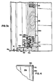
- Fig. 4 is an enlarged partial front plan view of a corner of the door member showing the joining of the weatherstrips.
- an inwardly swinging door assembly there is generally illustrated at 10 an inwardly swinging door assembly.
- the door assembly 10 is mounted in a frame 11. As shown in Fig. 1, the frame 11 is sized to receive not only the inwardly swinging door assembly 10 but also a stationary panel member, generally designated as 12. However, it is understood that the door assembly 10 may be mounted alone in a smaller frame or alternately, the frame may be larger to accommodate a plurality of stationary panel members 12. Still further, the position of the door assembly 10 may be varied within the frame 11. For example, where the frame 11 is sized sufficiently to accommodate two stationary panels and a door assembly 10, the door assembly 10 may be on either ends or in the center.
- the stationary panel member 12 which is optional to the present invention, may be of any suitable type well known in the industry.
- the panel member 12 includes a double pane window assembly 12a which consists of an inner glass panel and an outer glass panel cooperatively connected together and mounted to a first side rail 12b, second side rail 12c, top rail 12d and bottom rail 12e. Moldings 13 are cooperatively connected and in turn fastened into the side rails 12b-e by means of nails 14.
- the molding cooperatively connected to the first side rail 12b is fastened to the portion of the frame 11, as shown in Fig. 2b.
- the molding 13 cooperatively connected to the second side rail 12c is fastened by means of the nail 14 into the center support member 15.
- the sill member 16 who cross section is best seen in Fig. 3c, extends between the two generally vertical members of the frame 11.
- the sill member 16 comprises a wooden portion 16a cooperatively connected to a metal portion 16b to form the sill 16.
- a threshold 16c is cooperatively connected to the top of the sill 16.
- the center support member 15 extends between the sill member 16 and the top horizontal member of the frame 11.
- a first side jamb assembly 17 is cooperatively connected adjacent the first side rail 12b and extends between the frame 11 and sill 16.
- the first side jamb assembly 17 includes a first member 17a cooperatively connected to a second member 17b which forms the outer surface of the door opening.
- the second member 17b has a C-shaped section 17c which is adapted to receive an optional sliding screen door.
- Suitable weather stripping 18 is utilized between the first siderail 12b and the second member 17b of the first jamb assembly 17.
- a first astragal assembly 19 is cooperatively connected to the center support member 15 and extends between the horizontal upper member of the frame 11 and the sill 16.
- the astragal assembly 19 includes a first member 19a which is cooperatively connected to the center support member 15 and has a generally planar bottom member which extends beyond the edges of the center support member 15. The ends of the planar bottom 19b are angled slightly upward.
- the first member also has two upwardly extending members 19c which have a top portion which extends generally outward.
- the second member 19d of the astragal assembly 19 has a configuration, shown in cross section in Fig. 2a, which is symmetrical on both sides of the center support member 15.
- the second member 19d engages the outwardly extending portion of the upwardly extending member 19c and also the stationary panel 12.
- Suitable weatherstripping 20 may be utilized to weatherproof the stationary panel 12. While the above-described construction of the stationary panel 12 is preferred, it is understood that any suitably constructed stationary panel 12 may be utilized.
- the inwardly swinging door assembly 10 includes a door member 10a comprising a double pane assembly 21 mounted in a door panel 22.
- the door panel 22 has a first side rail 22a, second side rail 22b, top rail 22c, and bottom rail 22d, all cooperatively connected by means well known in the art to form the door panel.
- Suitable molding strips 23 may be utilized, where appropriate, around the double pane assembly 21.
- the construction of a door member 20, as described so far, is well known in the art.
- the first side rail 22a has an edge surface 24.
- the second rail 22b has an edge surface 25.
- the top rail 22c has a top edge surface 26 and the bottom rail 22d has a bottom edge surface 27.
- none of the edge surfaces 24 through 27 are planar. However, the designations for the edge surfaces generally designate the edges of the door member 20. However, as will be discussed more fully hereafter, the edge surfaces have cutouts to accommodate weatherstripping.
- Three hinges 28 are cooperatively connected to the center support member 15 and the door member 20, proximate the edge surface 24 by means well known in the art.
- the door assembly 10 is hingedly mounted for swinging inward into a building.
- the door assembly 10 also includes a multi-point closing and locking latch assembly generally designated as 29.
- the locking assembly 29, as shown, includes three separate locking sub assemblies 30, 31 and 32.
- the locking sub assemblies are interconnected by means of an espagnolette bar 33. Rotation of the handle 34 will cause the locking assembly 29 to move between a latched and unlatched position. Rotation of the handle 34 causes all three sub assemblies to move between the latched and unlatched position.
- Locking assemblies 29 are well-known in the art, but to date have essentially been used for improved security.
- the multi-point locking assembly 29, with the three locking sub assemblies 30 through 32 provide for increased protection against a forced entry.
- such a locking assembly 29 also has significant advantages with respect to the weather integrity of the door. By latching the door at 30 and 32 as well as at 31, the door is secured along three points. This will prevent bowing of the door at the top and bottom as well as maintain the integrity of the weatherseal proximate the locking sub assemblies 30 through 32.
- Such a latch assembly is described in U.S.-A-4,548,432, and is hereby incorporated by reference. Further, such a locking assembly 29 is available for purchase from Fixfabriken in Gotenberg, Sweden.
- the oval lines shown in phantom 60, 61 and 62 in Figs. 3a, 3b and 3c, respectively, show the locations of where the locking sub assemblies 30, 31 and 32 are positioned.
- the weatherstripping is cooperatively connected to the edge surfaces 24 through 27 on the door member 20.
- the weatherstripping 36 comprises four sections 36a through d and are carried entirely by the door member 20 and further are in one plane. Still further, the sections are cooperatively connected at the intersections to form one continuous weatherstrip around the door.
- the weatherstripping 36 can be seen in detail in Figs. 2a, 2c, 3a and 3c. As seen in Fig. 2a, the first edge surface 24 has a notched area in which the weatherstrip 36a is fastened.
- Weatherstrip section 36a as with the other sections, is a bulb type weatherstrip and has a first end 36e secured in a cavity 37 in door panel 22a.
- the section 36a has a protruding bulb section 36f, which is shown in a compressed configuration in Fig. 2a.
- the bulb section then continues and is again cooperatively connected into the cavity 37.
- the astragal assembly 19 has a weatherstrip engaging surface 19e that comes in contact with the bulb portion 36f of the section 36a.
- the second edge surface 25 has a notched area in which the weatherstrip 36b is fastened.
- Weatherstrip section 36b is a bulb-type weatherstrip and has a first end 36g secured in a cavity 38 in door panel 22b.
- the section 36b has a protruding bulb section 36h, which is shown in a compressed configuration in Fig. 2c.
- the bulb section then continues and is again cooperatively connected into the cavity 38.
- a second side jamb assembly 48 is similar to the first side jamb assembly 17.
- the second side jamb assembly 48 is cooperatively connected to the frame 11 and is proximate the side rail 22b and extends between the frame 11 and sill 16.
- the second side jamb assembly 48 includes a first member 48a cooperatively connected to a second member 48b which forms the outer surface of the door opening.
- the second member 48b has a C-shaped section 48c which is adapted to receive an optional sliding screen door.
- the second side jamb assembly 48 also includes a flange 48d which in turn has a generally perpendicular cross section piece 48e.
- the cross section piece 48e forms a weatherstrip engaging surface which contacts the bulb portion 36h of the weatherstrip section 36b.
- the edge surface 26 has a notched area in which the weatherstrip 36c is fastened.
- Weatherstrip section 36c is a bulb-type weatherstrip and has a first end 36i secured in a cavity 39 in the door panel 22c.
- the section 36c has a protruding bulb section 36j, which is shown in a compressed configuration in Fig. 3a.
- the bulb section then continues and is again cooperatively connected into the cavity 39.
- a top jamb assembly 50 as shown is Fig. 3a is cooperatively connected to the frame 11 and is proximate the top rail 22c and extends between the generally vertical upright members of the frame 11.
- the top jamb assembly 50 includes a first member 51 cooperatively connected to a second member 52.
- the second member 52 is adjacent and cooperatively connected to the frame 11, as previously discussed.
- the second member 52 includes a downwardly depending member 52a which forms a weatherstrip engaging surface which contacts the bulb portion 36j of weatherstrip section 36i.
- An optional assembly 53 may be attached to the top jamb assembly 50 when an optional screen is utilized.
- Weatherstrip section 36d is a bulb-type weatherstrip and has a first end 36k secured in a cavity 40 in the door panel 22d.
- the section 36d has a protruding bulb section 361, which is shown in a compressed configuration in Fig. 3c. The bulb section then continues and is again cooperatively connected into the cavity 40.
- the metal sill portion 16b has a downwardly sloping top surface 16d and two generally upright support members 16e and 16f. Further, the sill portion 16b extends past the support member 16e and has a further top surface 16g on which a guide 41 for a screen door may optionally be secured. At one end of the top surface 16d, an upwardly extending mounting member 16h is formed.
- a pressure equalization member, generally designated as 42, is cooperatively connected to the mounting member 16h of the middle sill 16b.
- the pressure equalization chamber extends the entire width between the frame 11 and the center support member 15.
- the pressure equalization member 42 has a first vertical member 43. The bottom end of the first vertical member 43 rests on the sill 16b.
- the height of the member 43 is greater than the pressure head that has to be withstood, approximately 38mm (1-1/2 inches).
- a second generally vertical member 44 has a bottom portion which engages the mounting member 16h.
- a horizontal section 45 is cooperatively connected between the first and second vertical sections 43 and 44.
- the second vertical member 44 has a weatherstrip engaging surface 44a that comes in contact with the weatherstrip 36d and forms the weatherseal.
- the top portion of the pressure equalization member 42 forms a generally U-shaped trough. This U-shaped trough has a plurality of drain holes 46 spaced along its length.
- the pressure equalization member 42 also an inverted U-shaped area which has a plurality of drain holes 47 spaced along its length.
- a water shed member 55 has a first member 55a which extends across the width of the door member 10a and is cooperatively connected to the bottom rail 22d and an outwardly and downwardly extending section 55b which acts as a water shed for any water which cascades down the outer surface of the door 10a, to prevent access of the cascading water into the pressure equalization member 42.
- Fig. 4 is a front plan view of one corner section of the door 10a.
- the four weatherstrip segments are cooperatively connected at the intersections to form a continuous weatherstrip around the door member. Only one corner of the door 10a is shown in detail, but the other four sections are similarly constructed.
- Fig. 4 shows that the bulb sections 36j and 36h are cooperatively connected along a seam 70 to form one continuous weatherstrip.
- the weatherstrip of the present invention is kept up off the ground and accordingly stays dryer than the weatherstrip of the prior art.
- the prior art often puts weatherstrip on the outside and the weatherstrip then becomes wet and air infiltration and water are then more easily able to pass through the weatherstrip barrier.
Landscapes
- Engineering & Computer Science (AREA)
- Civil Engineering (AREA)
- Structural Engineering (AREA)
- Specific Sealing Or Ventilating Devices For Doors And Windows (AREA)
Claims (14)
- Einwärts schwingende drehbare Türvorrichtung (10) zur Montage in einem Rahmen (11), wobei die Türvorrichtung umfaßt:(a) einen Türkörper (10a) mit einer oberen Randfläche (26), einer unteren Randfläche (27), und einer ersten und zweiten seitlichen Randfläche (24, 25);(b) Mittel (28) zur schwenkbaren Montage des besagten Türkörpers (10a) am Rahmen (11), wobei die besagten Montagemittel (28) nahe der besagten ersten und zweiten seitlichen Randflächen (24, 25) liegen;(c) ein Schloß (29), das in der Nähe der anderen der besagten ersten und zweiten seitlichen Randflächen (24, 25) montiert ist; und(d) eine ununterbrochene Einpunkt-Wetterleiste (36), die um den Türkörper (10a) herumläuft und Andruckflächen hat, die in einer Ebene liegen; dadurch gekennzeichnet, daß
das Schloß (29) ein Mehrpunktschloß ist, das so eingerichtet ist, daß es an mehr als einem Punkt in den Rahmen (11) eingreift;
die Wetterleiste (36) aus Streifen (36a, 36b, 36c, 36d) von Einpunkt-Wetterleisten besteht, die in zusammenwirkender Weise mit der besagten oberen Randfläche (26), unteren Randfläche (27) und der ersten und zweiten seitlichen Randfläche (24, 25) verbunden sind;
die besagten Streifen (36a, 36b, 36c, 36d) die einzig vorhandene Wetterleiste bilden;
ein Druckausgleichsteil (42) zusammenwirkend mit dem Rahmen (11) verbunden ist, um mit der besagten Wetterleiste (36d) zusammenzuwirken, die mit der besagten unteren Randfläche verbunden ist;
der Luftdurchzug der besagten Türvorrichtung (10), wie durch ASTM E-283 gemessen, 0,10 Kubikmeter pro Minute und pro Quadratmeter (0,34 Kubikfuß pro Minute und pro Quadratfuß) der besagten Türvorrichtung nicht überschreitet; und
besagte Türvorrichtung (10) das Durchdringen von Wasser verhindert, wie in ASTM E-547 bei 137 Pa (2,86 Pounds pro Quadratfuß) gemessen. - Türvorrichtung nach Anspruch 1, dadurch gekennzeichnet, daß das Schloß (29) ein Dreipunktschloß ist.
- Türvorrichtung nach Anspruch 1 oder 2, dadurch gekennzeichnet, daß die besagten Wetterleisten (36a, 36b, 36c, 36d) in einer Ebene liegen.
- Türvorrichtung nach einem der vorangehenden Ansprüche, dadurch gekennzeichnet, daß die besagte Wetterleiste (36) an den Schnittpunkten der besagten Flächen (24, 25, 26, 27) zusammenwirkend verbunden ist, um dadurch die besagte, ununterbrochene Wetterleiste (36) um den besagten Türkörper (10a) herum auszubilden.
- Türvorrichtung nach einem der vorangehenden Ansprüche, dadurch gekennzeichnet, daß das besagte Druckausgleichsteil (42) erste (43) und zweite (44) senkrechte Abschnitte und einen horizontalen Abschnitt (45) hat, der mit den besagten senkrechten Abschnitten (43, 44) zusammenwirkend verbunden ist.
- Türvorrichtung nach Anspruch 5, dadurch gekennzeichnet, daß der besagte horizontale Abschnitt (45) darin ausgebildete Abflußlöcher (46) aufweist und daß der besagte erste horizontale Abschnitt (43) darin ausgebildete Abflußlöcher (47) aufweist.
- Türvorrichtung nach Anspruch 6, dadurch gekennzeichnet, daß die besagten ersten (43) und zweiten (44) senkrechten Abschnitte mit Abstand von der besagten unteren Randfläche (27) angeordnet sind.
- Türvorrichtung nach Anspruch 6 oder 7, dadurch gekennzeichnet, daß die besagte untere Randfläche (27) eine obere und eine untere Seite hat, die durch eine im wesentlichen senkrechte Fläche zusammenwirkend verbunden sind, und besagte Wetterleiste (36) zusammenwirkend mit der besagten senkrechten Fläche und der besagten unteren Randfläche (27) zusammenwirkend verbunden ist, und besagte Wetterleiste (36), die mit der besagten senkrechten Fläche verbunden ist, an den besagten zweiten senkrechten Abschnitt (44) greift.
- Türvorrichtung nach einem der vorangehenden Ansprüche, dadurch gekennzeichnet, daß ein Wasserschutzteil (55b) zusammenwirkend mit dem Türkörper (10a) verbunden ist, um zu verhindern, daß Wasser, das am Türkörper (10a) herunterlaufen kann, in das Druckausgleichsteil (42) eintritt.
- Türvorrichtung nach einem der vorangehenden Ansprüche, dadurch gekennzeichnet, daß die Türvorrichtung (10) einer positiven/negativen Last von 2873 PA (60 PSF) bei Messung nach ASTM E-330 gemessen wird.
- Türvorrichtung nach einem der vorangehenden Ansprüche, dadurch gekennzeichnet, daß der besagte Luftdurchzug 0,06 Kubikmeter pro Minute und pro Quadratmeter (0,20 Kubikfuß pro Minute) nicht überschreitet.
- Türvorrichtung nach einem der vorangehenden Ansprüche, dadurch gekennzeichnet, daß die besagte Türvorrichtung (10) eine Prüfung nach ASTM E-547 bei 299 Pa (6,24 Pounds pro Quadratfuß) besteht.
- Türvorrichtung nach einem der vorangehenden Ansprüche, dadurch gekennzeichnet, daß der besagte Wetterstreifen (36) wulstförmige Wetterstreifen (36a, 36b, 36c, 36d) umfaßt.
- Türvorrichtung nach einem der vorangehenden Ansprüche, dadurch gekennzeichnet, daß das Schloß (29) durch die besagte andere der besagten ersten und zweiten seitlichen Randflächen (24, 25) in den Rahmen (11) eingreift.
Applications Claiming Priority (2)
| Application Number | Priority Date | Filing Date | Title |
|---|---|---|---|
| US16662188A | 1988-03-11 | 1988-03-11 | |
| US166621 | 2002-08-29 |
Publications (3)
| Publication Number | Publication Date |
|---|---|
| EP0414697A1 EP0414697A1 (de) | 1991-03-06 |
| EP0414697A4 EP0414697A4 (en) | 1991-06-19 |
| EP0414697B1 true EP0414697B1 (de) | 1993-06-09 |
Family
ID=22604043
Family Applications (1)
| Application Number | Title | Priority Date | Filing Date |
|---|---|---|---|
| EP19890903929 Expired - Lifetime EP0414697B1 (de) | 1988-03-11 | 1989-03-10 | Einwärts schwingende drehbare türvorrichtung |
Country Status (3)
| Country | Link |
|---|---|
| EP (1) | EP0414697B1 (de) |
| CA (1) | CA1320393C (de) |
| WO (1) | WO1989008765A1 (de) |
Families Citing this family (4)
| Publication number | Priority date | Publication date | Assignee | Title |
|---|---|---|---|---|
| JPH09184368A (ja) * | 1995-10-30 | 1997-07-15 | Ykk Corp Of America | 耐水ドア組立体 |
| JP3205858B2 (ja) * | 1995-10-31 | 2001-09-04 | ワイケイケイアーキテクチュラルプロダクツ株式会社 | サッシの下横枠材取付構造 |
| DE29708214U1 (de) * | 1997-05-07 | 1998-09-10 | Niemann, Hans Dieter, 50169 Kerpen | Türrahmen |
| CN2672245Y (zh) * | 2003-09-19 | 2005-01-19 | 南亚塑胶工业股份有限公司 | 内开式门扇的门槛结构 |
Family Cites Families (8)
| Publication number | Priority date | Publication date | Assignee | Title |
|---|---|---|---|---|
| CH192317A (de) * | 1937-01-27 | 1937-08-15 | Fermetal A G Fuer Metalldichtu | Fenster bezw. Türe. |
| CH415002A (de) * | 1964-05-26 | 1966-06-15 | Andreae & Dallmaier Ag | Wetterschenkel-Profil |
| FR2113767A1 (de) * | 1970-11-13 | 1972-06-30 | Foulon Roger | |
| US3777424A (en) * | 1972-10-19 | 1973-12-11 | Pullman Inc | Weather seal for railway car door |
| FR2300205A1 (fr) * | 1975-02-06 | 1976-09-03 | Gregoire Jean Claude | Appui pour fenetre, ou porte-fenetre, en bois |
| CA1164278A (en) * | 1980-11-12 | 1984-03-27 | William R. St. Aubin | Inswing door bottom and sill assembly |
| US4716683A (en) * | 1985-05-13 | 1988-01-05 | Rolscreen Company | Door weatherstripping assembly |
| DE8803661U1 (de) * | 1988-03-17 | 1988-05-19 | Schenk Fenster GmbH, 6973 Boxberg | Regenschutzschiene für die Türschwellen von Balkontüren |
-
1989
- 1989-03-10 EP EP19890903929 patent/EP0414697B1/de not_active Expired - Lifetime
- 1989-03-10 WO PCT/US1989/000982 patent/WO1989008765A1/en not_active Ceased
- 1989-03-10 CA CA000593390A patent/CA1320393C/en not_active Expired - Lifetime
Also Published As
| Publication number | Publication date |
|---|---|
| CA1320393C (en) | 1993-07-20 |
| EP0414697A4 (en) | 1991-06-19 |
| WO1989008765A1 (en) | 1989-09-21 |
| EP0414697A1 (de) | 1991-03-06 |
Similar Documents
| Publication | Publication Date | Title |
|---|---|---|
| US4999950A (en) | Inwardly swinging hinged door assembly | |
| US6367201B1 (en) | Width adaptable threshold assembly | |
| CA2342941C (en) | Swing adaptable astragal with lockable unitary flush bolt assemblies | |
| US3600854A (en) | Counterbalanced windows for curtain wall system | |
| US6243999B1 (en) | Blow-out prevention mechanism for windows | |
| US4167088A (en) | Doors for patios and the like | |
| US3888046A (en) | Automatic astragal | |
| US7624539B2 (en) | Combined sealing systems for pivoting door/window | |
| US5042199A (en) | Prefabricated window system | |
| US3460290A (en) | Sectional door | |
| US5822923A (en) | Door with swinging side light panel | |
| US20240209680A1 (en) | Fenestration unit including slidable glass panels | |
| US4570381A (en) | Single plane window or door structure | |
| US20090199495A1 (en) | Weatherstrip for double-hung window assembly | |
| US2917792A (en) | Window construction | |
| US3720025A (en) | Curtain wall system with vents | |
| CA1320393C (en) | Inwardly swinging door assembly | |
| US3173179A (en) | Metal window construction | |
| US2795306A (en) | Window structure | |
| US4420907A (en) | Shallow double hung window | |
| US4376353A (en) | Building structure | |
| US3469347A (en) | Window construction | |
| US3442049A (en) | Hinged double-hung windows | |
| JP2747870B2 (ja) | 高さの異なるサッシの連窓 | |
| US2875479A (en) | Sashless window structure |
Legal Events
| Date | Code | Title | Description |
|---|---|---|---|
| PUAI | Public reference made under article 153(3) epc to a published international application that has entered the european phase |
Free format text: ORIGINAL CODE: 0009012 |
|
| 17P | Request for examination filed |
Effective date: 19900905 |
|
| AK | Designated contracting states |
Kind code of ref document: A1 Designated state(s): CH DE GB IT LI NL SE |
|
| A4 | Supplementary search report drawn up and despatched |
Effective date: 19910426 |
|
| AK | Designated contracting states |
Kind code of ref document: A4 Designated state(s): CH DE GB IT LI NL SE |
|
| 17Q | First examination report despatched |
Effective date: 19911128 |
|
| GRAA | (expected) grant |
Free format text: ORIGINAL CODE: 0009210 |
|
| AK | Designated contracting states |
Kind code of ref document: B1 Designated state(s): CH DE GB IT LI NL SE |
|
| PG25 | Lapsed in a contracting state [announced via postgrant information from national office to epo] |
Ref country code: IT Free format text: LAPSE BECAUSE OF FAILURE TO SUBMIT A TRANSLATION OF THE DESCRIPTION OR TO PAY THE FEE WITHIN THE PRESCRIBED TIME-LIMIT;WARNING: LAPSES OF ITALIAN PATENTS WITH EFFECTIVE DATE BEFORE 2007 MAY HAVE OCCURRED AT ANY TIME BEFORE 2007. THE CORRECT EFFECTIVE DATE MAY BE DIFFERENT FROM THE ONE RECORDED. Effective date: 19930609 |
|
| REF | Corresponds to: |
Ref document number: 68907055 Country of ref document: DE Date of ref document: 19930715 |
|
| PLBE | No opposition filed within time limit |
Free format text: ORIGINAL CODE: 0009261 |
|
| STAA | Information on the status of an ep patent application or granted ep patent |
Free format text: STATUS: NO OPPOSITION FILED WITHIN TIME LIMIT |
|
| 26N | No opposition filed | ||
| EAL | Se: european patent in force in sweden |
Ref document number: 89903929.1 |
|
| PGFP | Annual fee paid to national office [announced via postgrant information from national office to epo] |
Ref country code: SE Payment date: 19960221 Year of fee payment: 8 |
|
| PGFP | Annual fee paid to national office [announced via postgrant information from national office to epo] |
Ref country code: DE Payment date: 19960223 Year of fee payment: 8 Ref country code: NL Payment date: 19960223 Year of fee payment: 8 |
|
| PGFP | Annual fee paid to national office [announced via postgrant information from national office to epo] |
Ref country code: CH Payment date: 19960312 Year of fee payment: 8 |
|
| PG25 | Lapsed in a contracting state [announced via postgrant information from national office to epo] |
Ref country code: SE Effective date: 19970311 |
|
| PG25 | Lapsed in a contracting state [announced via postgrant information from national office to epo] |
Ref country code: LI Effective date: 19970331 Ref country code: CH Effective date: 19970331 |
|
| PG25 | Lapsed in a contracting state [announced via postgrant information from national office to epo] |
Ref country code: NL Effective date: 19971001 |
|
| REG | Reference to a national code |
Ref country code: CH Ref legal event code: PL |
|
| NLV4 | Nl: lapsed or anulled due to non-payment of the annual fee |
Effective date: 19971001 |
|
| PG25 | Lapsed in a contracting state [announced via postgrant information from national office to epo] |
Ref country code: DE Effective date: 19971202 |
|
| EUG | Se: european patent has lapsed |
Ref document number: 89903929.1 |
|
| REG | Reference to a national code |
Ref country code: GB Ref legal event code: IF02 |
|
| PGFP | Annual fee paid to national office [announced via postgrant information from national office to epo] |
Ref country code: GB Payment date: 20030204 Year of fee payment: 15 |
|
| PG25 | Lapsed in a contracting state [announced via postgrant information from national office to epo] |
Ref country code: GB Free format text: LAPSE BECAUSE OF NON-PAYMENT OF DUE FEES Effective date: 20040310 |
|
| GBPC | Gb: european patent ceased through non-payment of renewal fee |
Effective date: 20040310 |