EP0412852A2 - Portable radio transceiver system having improved adaptor for transceiver and/or improved receive signal control arrangement - Google Patents
Portable radio transceiver system having improved adaptor for transceiver and/or improved receive signal control arrangement Download PDFInfo
- Publication number
- EP0412852A2 EP0412852A2 EP90308869A EP90308869A EP0412852A2 EP 0412852 A2 EP0412852 A2 EP 0412852A2 EP 90308869 A EP90308869 A EP 90308869A EP 90308869 A EP90308869 A EP 90308869A EP 0412852 A2 EP0412852 A2 EP 0412852A2
- Authority
- EP
- European Patent Office
- Prior art keywords
- signal
- switch means
- adaptor
- switch
- radio transceiver
- Prior art date
- Legal status (The legal status is an assumption and is not a legal conclusion. Google has not performed a legal analysis and makes no representation as to the accuracy of the status listed.)
- Granted
Links
Images

Classifications
-
- H—ELECTRICITY
- H04—ELECTRIC COMMUNICATION TECHNIQUE
- H04B—TRANSMISSION
- H04B1/00—Details of transmission systems, not covered by a single one of groups H04B3/00 - H04B13/00; Details of transmission systems not characterised by the medium used for transmission
- H04B1/38—Transceivers, i.e. devices in which transmitter and receiver form a structural unit and in which at least one part is used for functions of transmitting and receiving
- H04B1/3827—Portable transceivers
- H04B1/3877—Arrangements for enabling portable transceivers to be used in a fixed position, e.g. cradles or boosters
-
- H—ELECTRICITY
- H04—ELECTRIC COMMUNICATION TECHNIQUE
- H04B—TRANSMISSION
- H04B7/00—Radio transmission systems, i.e. using radiation field
- H04B7/02—Diversity systems; Multi-antenna system, i.e. transmission or reception using multiple antennas
- H04B7/04—Diversity systems; Multi-antenna system, i.e. transmission or reception using multiple antennas using two or more spaced independent antennas
- H04B7/08—Diversity systems; Multi-antenna system, i.e. transmission or reception using multiple antennas using two or more spaced independent antennas at the receiving station
- H04B7/0802—Diversity systems; Multi-antenna system, i.e. transmission or reception using multiple antennas using two or more spaced independent antennas at the receiving station using antenna selection
- H04B7/0805—Diversity systems; Multi-antenna system, i.e. transmission or reception using multiple antennas using two or more spaced independent antennas at the receiving station using antenna selection with single receiver and antenna switching
-
- H—ELECTRICITY
- H04—ELECTRIC COMMUNICATION TECHNIQUE
- H04B—TRANSMISSION
- H04B7/00—Radio transmission systems, i.e. using radiation field
- H04B7/02—Diversity systems; Multi-antenna system, i.e. transmission or reception using multiple antennas
- H04B7/04—Diversity systems; Multi-antenna system, i.e. transmission or reception using multiple antennas using two or more spaced independent antennas
- H04B7/08—Diversity systems; Multi-antenna system, i.e. transmission or reception using multiple antennas using two or more spaced independent antennas at the receiving station
- H04B7/0802—Diversity systems; Multi-antenna system, i.e. transmission or reception using multiple antennas using two or more spaced independent antennas at the receiving station using antenna selection
- H04B7/0825—Diversity systems; Multi-antenna system, i.e. transmission or reception using multiple antennas using two or more spaced independent antennas at the receiving station using antenna selection with main and with auxiliary or diversity antennas
Landscapes
- Engineering & Computer Science (AREA)
- Computer Networks & Wireless Communication (AREA)
- Signal Processing (AREA)
- Mobile Radio Communication Systems (AREA)
- Radio Transmission System (AREA)
Abstract
Description
- The present invention relates generally to a portable radio transceiver system, and more specifically to such a system which is provided with an improved adaptor for a portable radio transceiver and/or improved receive signal control arrangements.
- A portable radio transceiver, such as a portable radiotelephone or the like, is designed with primary importance placed on transportability and, accordingly, is required to be small in size and light in weight.
- A mobile transceiver is susceptible to so-called fading which is the variation of radio field intensity caused by changes in the transmission medium, and transmission path, with time. In order to minimize the effects of fading, a diversity scheme has been proposed. The diversity scheme is a method that is used to develop information from several signals transmitted over independently fading paths.
- In order to obtain wider usage of a portable radiotelephone, viz., enable the use both outside and inside of an automotive vehicle or the like, it is a current tendency that a portable radio transceiver is designed to be attachable to a vehicle mounted adaptor when used in a passenger compartment of a vehicle.
- However, a conventional vehicular adaptor is designed simply for coupling a portable radio transceiver to a car battery, a handset provided in the vehicle compartment, etc. More specifically, no prior art technique has suggested the concept of equipping a vehicular adaptor of the above mentioned type with circuitry for diversity reception.
- According to a known technique, an arrangement for diversity reception is provided in the portable radio transceiver itself. However, this results in an undesirable increase in size and weight of the device.
- Further, it is a common practice to provide a mobile telephone (i.e. portable radio transceiver or radiotelephone as it will be referred to hereinafter) with an indicator which shows the strength of the signal being received. An input signal to the indictor may further be used to indicate whether or not a portable radiotelephone is within a service area or not. However, a known portable radiotelephone is only provided with a single threshold level with which the receive signal strength is compared to indicate magnitude of electric field in which it is located. As a result, the known portable radiotelephone has encountered the problem that the receive signal strength varies notably between a portable mode and an in-car (vehicle mounted) mode.
- This difficulty is accentuated when a portable radiotelephone is coupled to a vehicular adaptor. That is to say, upon a portable telephone being set into the adaptor, a car battery energizes some portions of the portable telephone such as a radio frequency (RF) amplifier, a mixer, etc. Since a car battery voltage is higher than a rechargeable battery installed in the portable telephone, the indicator undesirably exhibits a higher value irrespective of the fact that the electric field strength has not changed. (By way of example, a car battery is 12.5 volts while a rechargeable battery 6 volts.)
- It is an object of the present invention to provide a portable radio transceiver system which includes an improved vehicular adaptor, to which diversity antennas are coupled and which includes a diversity switch and a diversity switch controller.
- Another object of the present invention is to provide a portable radio transceiver system wherein a portable transceiver is provided with an improved arrangement for exhibiting a correct receive signal strength.
- In brief, the above objects are achieved by a vehicle mounted adaptor which is provided with a diversity switch and a diversity switch controller. The adaptor is coupled to diversity antennas and removably receives a portable radiotelephone in an in-car mode. The portable radiotelephone is arranged to switch over from its own antenna to the diversity antennas upon insertion into the adaptor. The portable radiotelephone is further provided with an arrangement for exhibiting a correct receive signal strength irrespective of the fact it is set in the adaptor or used in a portable mode.
- More specifically a first aspect of the present invention comes in a portable radio transceiver system which includes a portable radio transceiver and an adaptor, said adaptor being mounted in a vehicle and removably receiving said portable radio transceiver, said adaptor comprising: diversity switch means, said diversity switch means being coupled to diversity antennas and adapted to select one of said diversity antennas and output a first signal to said portable radio transceiver; and switch control means, said switch control means being coupled to said diversity switch means, said switch control means receiving a second signal from said portable radio transceiver indicative of the strength of said first signal, and outputting a third signal in the event that a level of said second signal falls below a predetermined level, said third signal being applied to said diversity switch means and controlling the switching thereof.
- A second aspect of the present invention comes in a portable radio transceiver system which includes a portable radio transceiver and an adaptor, said adaptor being mounted in a vehicle and removably receiving said portable radio transceiver, said portable transceiver comprising: control signal generating means, said control signal generating means outputting a control signal which assumes a control level in response to attachment of said portable radio transceiver to said adaptor; first switch means, said first switch means being responsive to said control signal and switching from a battery installed therein to a vehicle mounted battery by way of said adaptor; a first signal generator, said first signal generator outputting a first reference signal; a second signal generator, said second signal generator outputting a second reference signal, said second reference signal having a level which is lower than a level of said first reference signal; second switch means, said second switch means being responsive to said control signal and switching between said first and second signal generators; and a comparator, said comparator being coupled to receive one of said first and second reference signals via said third switch, said comparator comparing a signal indicative of the strength of an antenna received signal with one of said first and second reference signals.
- A third aspect of the present invention comes in a portable radio transceiver system which includes a portable radio transceiver and an adaptor, said adaptor being mounted in a vehicle and removably receiving said portable radio transceiver, said adaptor comprising: diversity switch means, said diversity switch means being coupled to diversity antennas and adapted to select one of said diversity antennas and output a first signal to said portable radio transceiver; and switch control means, said switch control means being coupled to said diversity switch means, said switch control means receiving a second signal from said portable radio transceiver indicative of the strength of said first signal, and outputting a third signal in the event that a level of said second signal falls below a predetermined level, said third signal being applied to said diversity switch means and controlling the switching thereof, said portable radio transceiver comprising: control signal generating means, said control signal generating means outputting a control signal which assumes a control level in response to attachment of said portable radio transceiver to said adaptor; and first switch means, said first switch means being responsive to said control signal and switching from an antenna coupled to said portable transceiver to said diversity antennas.
- A fourth aspect of the present invention comes in a portable raido transceiver system which includes a portable radio transceiver and an adaptor, said adaptor being mounted in a vehicle and removably receiving said portable radio transceiver, said adaptor comprising: diversity switch means, said diversity switch means being coupled to diversity antennas and adapted to select one of said diversity antennas and output a first signal to said portable radio transceiver; and switch control means, said switch control means being coupled to said diversity switch means, said switch control means receiving a second signal from said portable radio transceiver indicative of the strength of said first signal, and outputting a third signal in the event that a level of said second signal falls below a predetermined level, said third signal being applied to said diversity switch means and controlling the switching thereof, said portable radio transceiver comprising: control signal generating means, said control signal generating means outputting a control signal which assumes a control level in response to attachment of said portable radio transceiver to said adaptor; first switch means, said first switch means being responsive to said control signal and switching from an antenna coupled to said portable transceiver to said diversity antennas; second switch means, said second switch means being responsive to said control signal and switching from a battery installed therein to a vehicle mounted battery coupled to said adaptor; a first signal generator, said first signal generator outputting a first reference signal; a second signal generator, said second signal generator outputting a second reference signal, said second reference signal having a level which is lower than a level of said first reference signal; third switch means, said third switch means being responsive to said control signal and switching between said first and second signal generators; and a comparator, said comparator being coupled to receive one of said first and second reference signals via said third switch, said comparator comparing said second signal with said one of said first and second reference signals.
- The features and advantages of the present invention will become more clearly appreciated from the following description taken in conjunction with the accompanying drawings in which like elements are denoted by like reference numerals and in which:
- Fig. 1 is a schematic perspective view of a portable radio transceiver system according to the present invention;
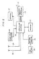
- Fig. 2 is a block diagram showing a portable radio transceiver system shown in Fig. 1;
- Fig. 3 is a block diagram showing a vehicular adaptor of the present invention together with a portable radiotelephone set;
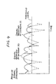
- Fig. 4 is a graph showing variations of signal strength received by diversity antennas; and
- Fig. 5 is a block diagram showing a portable radiotelephone and a vehicular adaptor which are arranged in accordance with the concept of the present invention.
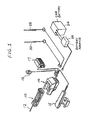
- Reference is now made to Fig. 1, wherein there is shown in perspective, a portable radiotelephone system according to the present invention.
- This system comprises a portable
subscriber type radiotelephone 10 which when used outside of the vehicle makes use of anantenna 12 which is included therein. On the other hand, when the device is used within the vehicle it is set in anadaptor 14. As shown, thisadaptor 14 is arranged to be coupled not only to ahandset 15 but to a "hands free"microphone 16 and aspeaker 17. - The
adaptor 14 is connected to first andsecond diversity antennas car battery 24 via asuitable battery adaptor 26. - Fig. 2 depicts the portable radiotelephone system shown in Fig. 1 in block diagram form. Description of this arrangement is deemed unnecessary.
- A first embodiment of this invention will be discussed with reference to Fig. 3.
- As shown, the
vehicular adaptor 14 is coupled to theportable radiotelephone 10 viaterminals adaptor 14 is equipped with adiversity switch 30 which switches over betweenterminals diversity switch controller 32. Theterminals switch 30 are respectively coupled to theantennas terminals 36a, 36b, while aterminal 30c of theswitch 30 is coupled to a duplexer (not shown in the Figure) of theportable set 10 via theterminals controller 32 has an output coupled to theswitch 30 and an input coupled to an intermediate frequency (IF) amplifier (not shown in this Figure) of theportable set 10 via theterminals portable radiotelephone 10 will be discussed in detail with reference to Fig. 5. - The
adaptor 14 has aset interface terminals blocks - When the
portable set 10 is coupled to thevehicular adaptor 14 as illustrated in Fig. 3, it is automatically switched over from theantenna 12 to thediversity antennas adaptor 14. The automatic switching will be described later with reference to Fig. 5. Thediversity switch controller 32 is supplied with a direct current signal derived from the IF amplifier, which is proportional to a radio frequency signal received at either of thediversity antennas controller 32 compares the inputted signal with a threshold level. In the event that thecontroller 22 detects that the signal inputted from theportable set 12 falls below the threshold level, the controller applies a control signal to thediversity switch 30. In response to the control signal, theswitch 30 selects the other antenna. - Fig. 4 is a graph showing variations of signal strength received by the
diversity antennas portable radiotelephone set 10. It will be understood from the drawing that theantennas - As will be appreciated from the foregoing, the
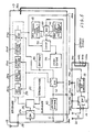
portable set 10 can effectively be reduced in size and weight in that the arrangement for diversity reception is provided in the vehicle mountedadaptor 14. - Reference is now made to Fig. 5, wherein a second embodiment of this invention is shown in block diagram form.
- The portable radiotelephone set 10 is provided with a
receiver 50 and atransmitter 52, both of which are interconnected to anantenna switch 54 via aduplexer 56. Theswitch 54 is coupled to theantenna 12 via a terminal 58, while coupled to thevehicular adaptor 14 via theswitches adaptor 14 has been described in detail in connection with Fig. 3. Theantenna switch 54 is controlled by a control signal C applied from avoltage divider 60 which is provided for lowering a car battery voltage appearing at the terminal 38d. The control signal C is also applied to twoswitches 62 and 64 which are respectively provided for switching power sources and for switching reference signals, as will be described. - The
receiver 50 takes the form of a double-superheterodyne arrangement in this particular embodiment, and includes anRF amplifier 50a, a first filter 50b, afirst mixer 50c, a second filter 50d and anIF amplifier 50e. Merely for the sake of simplifying the drawing, thereceiver 50 is not shown as being provided with a local oscillator to be coupled to themixer 50c and a second mixer preceded by theIF amplifier 50e together with another local oscillator connected thereto. Further, thetransmitter 52 is not shown in detail in that the present invention is not concerned therewith. - As shown, the
power supply switch 62 is coupled to theRF amplifier 50a and themixer 50c in this particular embodiment, the reason of which is to increase the output of themixer 50c in the case where theportable set 10 is coupled to thecar battery 24 when placed in theadaptor 14. Theportable set 10 is provided with abattery 66. Although not shown in detail in the drawing, it should be noted that thebattery 66 is recharged when theportable set 12 is set in thevehicular adaptor 14. As will be appreciated this circuit arrangement is omitted for the sake of simplicity. - The switch 64 is coupled to two
reference signal generators generator 68 is switched to acomparator 72 when theportable set 10 is coupled to the adaptor 14 (in-car mode), while thegenerator 70 is coupled to thecomparator 72 upon theportable set 10 being detached from the adaptor 14 (viz., used in the portable mode). Thecomparator 72 compares the output of the switch 64 with the above-mentioned DC voltage which is proportional to the receive signal strength. It should be noted that the DC voltage is obtained at the stage of theIF amplifier 50e by a conventional technique. - Returning to the
generators comparator 72 outputs a signal whose level is substantially identical independently of the above-mentioned two modes. Accordingly, anindicator 74 is able to exhibit substantially the same level irrespective of the fact it is set in theadaptor 14 or used in the portable mode. In the above description, each of thegenerators generators - The operation of the Fig. 5 arrangement will further be discussed in more detail.
- When the
portable set 10 is coupled to thevehicular adaptor 14 as illustrated, a car battery voltage appearing at the terminal 34d is applied to thevoltage divider 60 and theswitch 62 by way of the terminal 38d. Thevoltage divider 60 lowers the car battery voltage to a level appropriate to control theswitches switch 54 selects thediversity antennas portable set 12, now coupled to theadaptor 14, is ready for diversity reception. - Further, in response to the control signal C assuming a high level, the
switch 62 selects the car battery voltage while the switch 64 selects thereference generator 68. - In the event the
portable set 10 is detached from the adaptor, theswitches antenna 12, thebattery 66 and thereference generator 70, respectively. - It should be noted that throughout the instant specification a term "radiotelephone" is predominantly used. However, the scope of this invention is such as to include any type of mobile radio transceiver.
- While the foregoing description describes two embodiments according to the present invention, the various alternatives and modifications possible without departing from the scope of the present invention, which is limited only by the appended claims, will be apparent to those skilled in the art.
Claims (8)
diversity switch means, said diversity switch means being coupled to diversity antennas and adapted to select one of said diversity antennas and output a first signal to said portable radio transceiver; and
switch control means, said switch control means being coupled to said diversity switch means, said switch control means receiving a second signal from said portable radio transceiver indicative of the strength of said first signal, and outputting a third signal in the event that a level of said second signal falls below a predetermined level, said third signal being applied to said diversity switch means and controlling the switching thereof.
control signal generating means, said control signal generating means outputting a control signal which assumes a control level in response to attachment of said portable radio transceiver to said adaptor; and
first switch means, said first switch means being responsive to said control signal and switching from an antenna coupled to said portable transceiver to said diversity antennas.
second switch means, said second switch means being responsive to said control signal and switching from a battery installed therein to a vehicle mounted battery coupled to said adaptor;
a first signal generator, said first signal generator outputting a first reference signal;
a second signal generator, said second signal generator outputting a second reference signal, said second reference signal having a level which is lower than a level of said first reference signal;
third switch means, said third switch means being responsive to said control signal and switching between said first and second signal generators; and
a comparator, said comparator being coupled to receive one of said first and second reference signals via said third switch means, said comparator comparing said second signal with one of said first and second reference signals.
control signal generating means, said control signal generating means outputting a control signal which assumes a control level in response to attachment of said portable radio transceiver to said adaptor;
first switch means, said first switch means being responsive to said control signal and switching from a battery installed therein to a vehicle mounted battery by way of said adaptor;
a first signal generator, said first signal generator outputting a first reference signal;
a second signal generator, said second signal generator outputting a second reference signal, said second reference signal having a level which is lower than a level of said first reference signal;
second switch means, said second switch means being responsive to said control signal and switching between said first and second signal generators; and
a comparator, said comparator being coupled to receive one of said first and second reference signals via said second switch, said comparator comparing a signal indicative of the strength of an antenna received signal with one of said first and second reference signals.
diversity switch means, said diversity switch means being coupled to diversity antennas and adapted to select one of said diversity antennas and output a first signal to said portable radio transceiver;
switch control means, said switch control means being coupled to said diversity switch means, said switch control means receiving a second signal from said portable radio transceiver indicative of the strength of said first signal, and outputting a third signal in the event that a level of said second signal falls below a predetermined level, said third signal being applied to said diversity switch means and controlling the switching thereof, and
wherein said portable transceiver further comprises:
third switch means, said third switch means being responsive to said control signal and switching from an antenna coupled to said portable transceiver to said diversity antennas.
diversity switch means, said diversity switch means being coupled to diversity antennas and adapted to select one of said diversity antennas and output a first signal to said portable radio transceiver; and
switch control means, said switch control means being coupled to said diversity switch means, said switch control means receiving a second signal from said portable radio transceiver indicative of the strength of said first signal, and outputting a third signal in the event that a level of said second signal falls below a predetermined level, said third signal being applied to said diversity switch means and controlling the switching thereof,
said portable radio transceiver comprising:
control signal generating means, said control signal generating means outputting a control signal which assumes a control level in response to attachment of said portable radio transceiver to said adaptor; and
first switch means, said first switch means being responsive to said control signal and switching from an antenna coupled to said portable transceiver to said diversity antennas.
second switch means, said second switch means being responsive to said control signal and switching from a battery installed therein to a vehicle mounted battery coupled to said adaptor;
a first signal generator, said first signal generator outputting a first reference signal;
a second signal generator, said second signal generator outputting a second reference signal, said second reference signal having a level which is lower than a level of said first reference signal;
third switch means, said third switch means being responsive to said control signal and switching between said first and second signal generators; and
a comparator, said comparator being coupled to receive one of said first and second reference signals via said third switch, said comparator comparing said second signal with said one of said first and second reference signals.
diversity switch means, said diversity switch means being coupled to diversity antennas and adapted to select one of said diversity antennas and output a first signal to said portable radio transceiver; and
switch control means, said switch control means being coupled to said diversity switch means, said switch control means receiving a second signal from said portable radio transceiver indicative of the strength of said first signal, and outputting a third signal in the event that a level of said second signal falls below a predetermined level, said third signal being applied to said diversity switch means and controlling the switching thereof,
said portable radio transceiver comprising:
control signal generating means, said control signal generating means outputting a control signal which assumes a control level in response to attachment of said portable radio transceiver to said adaptor;
first switch means, said first switch means being responsive to said control signal and switching from an antenna coupled to said portable transceiver to said diversity antennas;
second switch means, said second switch means being responsive to said control signal and switching from a battery installed therein to a vehicle mounted battery coupled to said adaptor;
a first signal generator, said first signal generator outputting a first reference signal;
a second signal generator, said second signal generator outputting a second reference signal, said second reference signal having a level which is lower than a level of said first reference signal;
third switch means, said third switch means being responsive to said control signal and switching between said first and second signal generators; and
a comparator, said comparator being coupled to receive one of said first and second reference signals via said third switch, said comparator comparing said second signal with said one of said first and second reference signals.
Applications Claiming Priority (4)
| Application Number | Priority Date | Filing Date | Title |
|---|---|---|---|
| JP206699/89 | 1989-08-11 | ||
| JP1206699A JP2752713B2 (en) | 1989-08-11 | 1989-08-11 | Adapter for portable radio |
| JP23081589A JP2751455B2 (en) | 1989-09-05 | 1989-09-05 | Receive electric field strength judgment method |
| JP230815/89 | 1989-09-05 |
Publications (3)
| Publication Number | Publication Date |
|---|---|
| EP0412852A2 true EP0412852A2 (en) | 1991-02-13 |
| EP0412852A3 EP0412852A3 (en) | 1992-04-15 |
| EP0412852B1 EP0412852B1 (en) | 1997-01-08 |
Family
ID=26515805
Family Applications (1)
| Application Number | Title | Priority Date | Filing Date |
|---|---|---|---|
| EP90308869A Expired - Lifetime EP0412852B1 (en) | 1989-08-11 | 1990-08-13 | Portable radio transceiver system having improved adaptor for transceiver and/or improved receive signal control arrangement |
Country Status (5)
| Country | Link |
|---|---|
| US (1) | US5261121A (en) |
| EP (1) | EP0412852B1 (en) |
| AU (1) | AU639010B2 (en) |
| CA (1) | CA2022605C (en) |
| DE (1) | DE69029619T2 (en) |
Cited By (9)
| Publication number | Priority date | Publication date | Assignee | Title |
|---|---|---|---|---|
| DE9303657U1 (en) * | 1993-03-12 | 1993-05-13 | Imhof, Augustin, 7619 Steinach, De | |
| EP0586827A1 (en) * | 1992-09-10 | 1994-03-16 | Roke Manor Research Limited | Portable radio communication apparatus |
| EP0641088A1 (en) * | 1992-05-01 | 1995-03-01 | Kabushiki Kaisha Toshiba | Wireless device |
| WO1995020271A1 (en) * | 1994-01-25 | 1995-07-27 | Bjorn Karl Emil Jondelius | Mobile telephone extension units |
| AT449U1 (en) * | 1994-01-21 | 1995-10-25 | Telebox Autotelefon Zubehoer G | ADAPTER FOR A HAND RADIO COMMUNICATION DEVICE |
| WO1997024624A1 (en) * | 1995-12-27 | 1997-07-10 | Qualcomm Incorporated | Antenna adapter |
| WO1997048147A1 (en) * | 1996-06-10 | 1997-12-18 | Ericsson Inc. | Mobile cradle antenna and heat sink combination |
| WO1998025322A1 (en) * | 1996-12-02 | 1998-06-11 | Qualcomm Incorporated | Antenna adapter |
| WO2013150346A1 (en) * | 2011-10-25 | 2013-10-10 | Poynting Antennas (Pty) Limited | Communications aid for end user cellular device |
Families Citing this family (48)
| Publication number | Priority date | Publication date | Assignee | Title |
|---|---|---|---|---|
| JP2570582B2 (en) * | 1993-07-23 | 1997-01-08 | 日本電気株式会社 | Portable radio |
| US5488649A (en) | 1994-05-06 | 1996-01-30 | Motorola, Inc. | Method for validating a communication link |
| GB2292022B (en) * | 1994-01-06 | 1997-07-30 | Motorola Inc | Power adaptor with integral radio frequency port |
| US5423083A (en) * | 1994-02-14 | 1995-06-06 | Stellmach; Robert N. | Selector adaptor for converting a cellular phone to a bag phone |
| JP3360703B2 (en) * | 1994-11-08 | 2002-12-24 | ソニー株式会社 | Mobile phone |
| US5574987A (en) * | 1994-12-20 | 1996-11-12 | Qualcomm Incorporated | Antenna switching apparatus |
| US5588041A (en) * | 1995-01-05 | 1996-12-24 | Motorola, Inc. | Cellular speakerphone and method of operation thereof |
| AU693350B2 (en) * | 1995-04-11 | 1998-06-25 | Mold-Tech Plastics Limited Partnership | Interface for portable communications device |
| JPH08293846A (en) * | 1995-04-19 | 1996-11-05 | Sony Corp | Transmission/reception device |
| US5732335A (en) * | 1995-04-28 | 1998-03-24 | Telefonaktiebolaget Lm Ericsson | Externally controlled output power by means of antenna keying |
| US6732077B1 (en) * | 1995-05-12 | 2004-05-04 | Trimble Navigation Limited | Speech recognizing GIS/GPS/AVL system |
| US5754962A (en) * | 1995-07-27 | 1998-05-19 | Ericsson Inc. | Method and apparatus for indicating an operable or non-operable connection between a portable radio and a vehicle kit |
| JP3612632B2 (en) * | 1995-08-11 | 2005-01-19 | 富士通株式会社 | In-vehicle adapter for mobile phones |
| US5710984A (en) * | 1995-10-20 | 1998-01-20 | Sharp Microelectronics Technology, Inc. | Radio transceiver with impedance matched test port |
| JP3382764B2 (en) * | 1995-10-27 | 2003-03-04 | 松下電器産業株式会社 | Wireless mobile |
| US5797088A (en) * | 1995-10-30 | 1998-08-18 | Stamegna; Ivano | Vehicular audio system incorporating detachable cellular telephone |
| US6085078A (en) * | 1995-10-30 | 2000-07-04 | Stamegna; Ivano | Vehicular audio system incorporating detachable cellular telephone |
| US20080207197A1 (en) | 1997-07-30 | 2008-08-28 | Steven Tischer | Apparatus, method, and computer-readable medium for interfacing devices with communications networks |
| US7194083B1 (en) | 2002-07-15 | 2007-03-20 | Bellsouth Intellectual Property Corporation | System and method for interfacing plain old telephone system (POTS) devices with cellular networks |
| US7149514B1 (en) | 1997-07-30 | 2006-12-12 | Bellsouth Intellectual Property Corp. | Cellular docking station |
| US6072993A (en) * | 1997-08-12 | 2000-06-06 | Sony Corporation | Portable radio transceiver with diplexer-switch circuit for dual frequency band operation |
| US6216012B1 (en) * | 1997-11-07 | 2001-04-10 | Conexant Systems, Inc. | Dualband power amplifier control using a single power amplifier controller |
| USD419160S (en) * | 1998-05-14 | 2000-01-18 | Northrop Grumman Corporation | Personal communications unit docking station |
| USD421002S (en) * | 1998-05-15 | 2000-02-22 | Northrop Grumman Corporation | Personal communications unit handset |
| US6304559B1 (en) | 1998-05-15 | 2001-10-16 | Northrop Grumman Corporation | Wireless communications protocol |
| US6041243A (en) * | 1998-05-15 | 2000-03-21 | Northrop Grumman Corporation | Personal communications unit |
| US6223062B1 (en) | 1998-05-15 | 2001-04-24 | Northrop Grumann Corporation | Communications interface adapter |
| US6243573B1 (en) | 1998-05-15 | 2001-06-05 | Northrop Grumman Corporation | Personal communications system |
| US6169730B1 (en) | 1998-05-15 | 2001-01-02 | Northrop Grumman Corporation | Wireless communications protocol |
| US6141426A (en) * | 1998-05-15 | 2000-10-31 | Northrop Grumman Corporation | Voice operated switch for use in high noise environments |
| US6304764B1 (en) | 1999-01-06 | 2001-10-16 | Priority Tech, Inc. | Hands-free cellular phone kit |
| US6493546B2 (en) * | 1999-03-05 | 2002-12-10 | Xm Satellite Radio Inc. | System for providing signals from an auxiliary audio source to a radio receiver using a wireless link |
| US6411802B1 (en) | 1999-03-15 | 2002-06-25 | Bellsouth Intellectual Property Management Corporation | Wireless backup telephone device |
| US6529746B1 (en) * | 2000-10-02 | 2003-03-04 | Motorola, Inc. | Wireless device cradle with spatial antenna diversity capability |
| US7120454B1 (en) * | 2001-12-26 | 2006-10-10 | Bellsouth Intellectual Property Corp. | Auto sensing home base station for mobile telephone with remote answering capabilites |
| US6973291B1 (en) * | 2001-12-28 | 2005-12-06 | Symbol Technologies, Inc. | Vehicle cradle system and methodology for hand held devices |
| US7010325B1 (en) | 2002-06-11 | 2006-03-07 | Sprint Spectrum L.P. | Wireless repeater with wireless telephone adapter |
| US8554187B2 (en) | 2002-07-15 | 2013-10-08 | At&T Intellectual Property I, L.P. | Apparatus and method for routing communications between networks and devices |
| US8543098B2 (en) | 2002-07-15 | 2013-09-24 | At&T Intellectual Property I, L.P. | Apparatus and method for securely providing communications between devices and networks |
| US8000682B2 (en) | 2002-07-15 | 2011-08-16 | At&T Intellectual Property I, L.P. | Apparatus and method for restricting access to data |
| US8416804B2 (en) | 2002-07-15 | 2013-04-09 | At&T Intellectual Property I, L.P. | Apparatus and method for providing a user interface for facilitating communications between devices |
| US7200424B2 (en) | 2002-07-15 | 2007-04-03 | Bellsouth Intelectual Property Corporation | Systems and methods for restricting the use and movement of telephony devices |
| US8526466B2 (en) | 2002-07-15 | 2013-09-03 | At&T Intellectual Property I, L.P. | Apparatus and method for prioritizing communications between devices |
| US8275371B2 (en) | 2002-07-15 | 2012-09-25 | At&T Intellectual Property I, L.P. | Apparatus and method for providing communications and connection-oriented services to devices |
| US7571102B2 (en) * | 2003-04-29 | 2009-08-04 | Ford Motor Company | Controller for use with a motor vehicle |
| JP4098159B2 (en) | 2003-05-28 | 2008-06-11 | オリンパス株式会社 | Actuator drive |
| US7079015B2 (en) * | 2003-06-24 | 2006-07-18 | Ford Motor Company | System for connecting wireless devices to a vehicle |
| US20050245234A1 (en) * | 2004-04-28 | 2005-11-03 | Michael Stopek | Antenna and headset for a wireless device |
Citations (5)
| Publication number | Priority date | Publication date | Assignee | Title |
|---|---|---|---|---|
| EP0206775A2 (en) * | 1985-06-21 | 1986-12-30 | Toyota Jidosha Kabushiki Kaisha | Automobile antenna system |
| US4633519A (en) * | 1983-03-31 | 1986-12-30 | Tokyo Shibaura Denki Kabushiki Kaisha | Diversity reception system in a portable radio apparatus |
| JPS6451723A (en) * | 1987-08-22 | 1989-02-28 | Hitachi Ltd | Lighting system for cellular system radio telephone set |
| EP0310318A2 (en) * | 1987-09-28 | 1989-04-05 | Kabushiki Kaisha Toshiba | Radio telephone apparatus |
| US4845505A (en) * | 1987-02-13 | 1989-07-04 | Toyota Jidosha Kabushiki Kaisha | Automobile antenna system for diversity reception |
Family Cites Families (8)
| Publication number | Priority date | Publication date | Assignee | Title |
|---|---|---|---|---|
| JPS6187434A (en) * | 1984-10-04 | 1986-05-02 | Nec Corp | Portable radio equipment |
| DE3517247A1 (en) * | 1985-05-13 | 1986-11-13 | Gerhard Prof. Dr.-Ing. 8012 Ottobrunn Flachenecker | ANTENNA DIVERSITY RECEIVING SYSTEM FOR ELIMINATION OF RECEIVING ERRORS |
| JP2702109B2 (en) * | 1985-08-29 | 1998-01-21 | 日本電気株式会社 | Portable radio |
| US4673861A (en) * | 1986-04-03 | 1987-06-16 | General Electric Company | Battery charger/remote control for portable radio devices |
| JPH0779299B2 (en) * | 1986-08-30 | 1995-08-23 | 日本電気株式会社 | Portable radio |
| JPH0650825B2 (en) * | 1988-01-29 | 1994-06-29 | 日本電気株式会社 | Wireless telephone |
| JPH01208915A (en) * | 1988-02-16 | 1989-08-22 | Sanyo Electric Co Ltd | Fm receiver |
| JP2552928B2 (en) * | 1990-01-31 | 1996-11-13 | 三菱電機株式会社 | Antenna selection diversity receiver |
-
1990
- 1990-08-13 DE DE69029619T patent/DE69029619T2/en not_active Expired - Fee Related
- 1990-08-13 CA CA002022605A patent/CA2022605C/en not_active Expired - Fee Related
- 1990-08-13 AU AU60952/90A patent/AU639010B2/en not_active Ceased
- 1990-08-13 EP EP90308869A patent/EP0412852B1/en not_active Expired - Lifetime
- 1990-08-13 US US07/566,672 patent/US5261121A/en not_active Expired - Fee Related
Patent Citations (5)
| Publication number | Priority date | Publication date | Assignee | Title |
|---|---|---|---|---|
| US4633519A (en) * | 1983-03-31 | 1986-12-30 | Tokyo Shibaura Denki Kabushiki Kaisha | Diversity reception system in a portable radio apparatus |
| EP0206775A2 (en) * | 1985-06-21 | 1986-12-30 | Toyota Jidosha Kabushiki Kaisha | Automobile antenna system |
| US4845505A (en) * | 1987-02-13 | 1989-07-04 | Toyota Jidosha Kabushiki Kaisha | Automobile antenna system for diversity reception |
| JPS6451723A (en) * | 1987-08-22 | 1989-02-28 | Hitachi Ltd | Lighting system for cellular system radio telephone set |
| EP0310318A2 (en) * | 1987-09-28 | 1989-04-05 | Kabushiki Kaisha Toshiba | Radio telephone apparatus |
Non-Patent Citations (3)
| Title |
|---|
| * abstract; figure 1 * * |
| IEEE TRANSACTIONS ON VEHICULAR TECHNOLOGY. vol. 22, no. 4, November 1973, NEW YORK US pages 173 - 184; RUSTAKO ET AL.: 'Performance of feedback and switch space diversity 900Mhz mobile radio systems with rayleigh fading.' * |
| PATENT ABSTRACTS OF JAPAN vol. 13, no. 254 (E-772)(3602) 13 June 1989 & JP-A-1 051 723 ( HITACHI ) 28 February 1989 * |
Cited By (16)
| Publication number | Priority date | Publication date | Assignee | Title |
|---|---|---|---|---|
| US5659888A (en) * | 1992-05-01 | 1997-08-19 | Kabushiki Kaisha Toshiba | Radio telecommunication apparatus |
| EP0641088A1 (en) * | 1992-05-01 | 1995-03-01 | Kabushiki Kaisha Toshiba | Wireless device |
| EP0641088A4 (en) * | 1992-05-01 | 1995-11-08 | Toshiba Kk | Wireless device. |
| EP0586827A1 (en) * | 1992-09-10 | 1994-03-16 | Roke Manor Research Limited | Portable radio communication apparatus |
| DE9303657U1 (en) * | 1993-03-12 | 1993-05-13 | Imhof, Augustin, 7619 Steinach, De | |
| AT449U1 (en) * | 1994-01-21 | 1995-10-25 | Telebox Autotelefon Zubehoer G | ADAPTER FOR A HAND RADIO COMMUNICATION DEVICE |
| WO1995020271A1 (en) * | 1994-01-25 | 1995-07-27 | Bjorn Karl Emil Jondelius | Mobile telephone extension units |
| US6043780A (en) * | 1995-12-27 | 2000-03-28 | Funk; Thomas J. | Antenna adapter |
| US5959583A (en) * | 1995-12-27 | 1999-09-28 | Qualcomm Incorporated | Antenna adapter |
| WO1997024624A1 (en) * | 1995-12-27 | 1997-07-10 | Qualcomm Incorporated | Antenna adapter |
| AU724193B2 (en) * | 1995-12-27 | 2000-09-14 | Qualcomm Incorporated | Antenna adapter |
| WO1997048147A1 (en) * | 1996-06-10 | 1997-12-18 | Ericsson Inc. | Mobile cradle antenna and heat sink combination |
| US6031492A (en) * | 1996-06-10 | 2000-02-29 | Ericsson Inc. | Mobile cradle antenna and heat sink enhancement |
| WO1998025322A1 (en) * | 1996-12-02 | 1998-06-11 | Qualcomm Incorporated | Antenna adapter |
| AU737100B2 (en) * | 1996-12-02 | 2001-08-09 | Qualcomm Incorporated | Antenna adapter |
| WO2013150346A1 (en) * | 2011-10-25 | 2013-10-10 | Poynting Antennas (Pty) Limited | Communications aid for end user cellular device |
Also Published As
| Publication number | Publication date |
|---|---|
| CA2022605A1 (en) | 1991-02-12 |
| EP0412852B1 (en) | 1997-01-08 |
| US5261121A (en) | 1993-11-09 |
| EP0412852A3 (en) | 1992-04-15 |
| DE69029619T2 (en) | 1997-05-22 |
| DE69029619D1 (en) | 1997-02-20 |
| CA2022605C (en) | 1995-01-03 |
| AU6095290A (en) | 1991-02-14 |
| AU639010B2 (en) | 1993-07-15 |
Similar Documents
| Publication | Publication Date | Title |
|---|---|---|
| US5261121A (en) | Portable radio transceiver system having improved adaptor and/or improved receiver signal control arrangement | |
| KR960004319B1 (en) | An adapter unit for adaptively supplying a portable radio telephone with power | |
| EP0326413B1 (en) | Radio telephone set used as portable set and vehicle-mounted set | |
| US5033109A (en) | Pocket transceiver | |
| US5461262A (en) | Vehicle mounted adaptor for a portable radio transceiver | |
| CA2035425C (en) | Overdischarge and overvoltage protection circuit for a battery in a portable and mobile communication system | |
| US5898908A (en) | RF gain enhancement for cellular telephone | |
| US5497507A (en) | Portable wireless telephone apparatus with use specific power monitoring | |
| EP0692885A1 (en) | Wireless telephone | |
| EP0326184A2 (en) | Charge control circuit for cordless telephone system | |
| JPH04239251A (en) | Radio telephony equipment adaptor | |
| EP0771082A2 (en) | Mobile station without a transmission/reception duplexer | |
| CA2021066C (en) | Apparatus for controlling a power supply of an electric machine in a vehicle | |
| US6449499B1 (en) | Dual-mode radio connected to an apparatus for communicating through in analog mode | |
| US5149985A (en) | Two-battery supply for operating and waiting modes of a carphone | |
| CA2037050C (en) | Portable telephone with power source/mode change during calls | |
| EP0388895A2 (en) | Variable transmission power type transmitter | |
| US6009316A (en) | Receiver with an antenna switch, in which sensitivity and quality of reception is improved | |
| US6377826B1 (en) | Charging system of mobile telephone | |
| US5438696A (en) | Method and apparatus for controlling radio frequency interference generated by a voltage multiplier | |
| JP2699865B2 (en) | Power supply system for in-vehicle portable wireless telephone | |
| KR100222428B1 (en) | Battery charging current control device and method by portable unit | |
| JPH11299116A (en) | Power supply adaptor, electronic apparatus and signal transmission system | |
| JPH06112877A (en) | Portable radio telephone set | |
| JP3063891B2 (en) | mobile phone |
Legal Events
| Date | Code | Title | Description |
|---|---|---|---|
| PUAI | Public reference made under article 153(3) epc to a published international application that has entered the european phase |
Free format text: ORIGINAL CODE: 0009012 |
|
| 17P | Request for examination filed |
Effective date: 19900831 |
|
| AK | Designated contracting states |
Kind code of ref document: A2 Designated state(s): DE GB NL |
|
| PUAL | Search report despatched |
Free format text: ORIGINAL CODE: 0009013 |
|
| AK | Designated contracting states |
Kind code of ref document: A3 Designated state(s): DE GB NL |
|
| 17Q | First examination report despatched |
Effective date: 19930929 |
|
| GRAG | Despatch of communication of intention to grant |
Free format text: ORIGINAL CODE: EPIDOS AGRA |
|
| GRAH | Despatch of communication of intention to grant a patent |
Free format text: ORIGINAL CODE: EPIDOS IGRA |
|
| GRAH | Despatch of communication of intention to grant a patent |
Free format text: ORIGINAL CODE: EPIDOS IGRA |
|
| GRAA | (expected) grant |
Free format text: ORIGINAL CODE: 0009210 |
|
| AK | Designated contracting states |
Kind code of ref document: B1 Designated state(s): DE GB NL |
|
| REF | Corresponds to: |
Ref document number: 69029619 Country of ref document: DE Date of ref document: 19970220 |
|
| PGFP | Annual fee paid to national office [announced via postgrant information from national office to epo] |
Ref country code: NL Payment date: 19970831 Year of fee payment: 8 |
|
| PLBE | No opposition filed within time limit |
Free format text: ORIGINAL CODE: 0009261 |
|
| STAA | Information on the status of an ep patent application or granted ep patent |
Free format text: STATUS: NO OPPOSITION FILED WITHIN TIME LIMIT |
|
| 26N | No opposition filed | ||
| PG25 | Lapsed in a contracting state [announced via postgrant information from national office to epo] |
Ref country code: NL Free format text: LAPSE BECAUSE OF NON-PAYMENT OF DUE FEES Effective date: 19990301 |
|
| NLV4 | Nl: lapsed or anulled due to non-payment of the annual fee |
Effective date: 19990301 |
|
| REG | Reference to a national code |
Ref country code: GB Ref legal event code: IF02 |
|
| PGFP | Annual fee paid to national office [announced via postgrant information from national office to epo] |
Ref country code: GB Payment date: 20040811 Year of fee payment: 15 |
|
| PGFP | Annual fee paid to national office [announced via postgrant information from national office to epo] |
Ref country code: DE Payment date: 20040826 Year of fee payment: 15 |
|
| PG25 | Lapsed in a contracting state [announced via postgrant information from national office to epo] |
Ref country code: GB Free format text: LAPSE BECAUSE OF NON-PAYMENT OF DUE FEES Effective date: 20050813 |
|
| PG25 | Lapsed in a contracting state [announced via postgrant information from national office to epo] |
Ref country code: DE Free format text: LAPSE BECAUSE OF NON-PAYMENT OF DUE FEES Effective date: 20060301 |
|
| GBPC | Gb: european patent ceased through non-payment of renewal fee |
Effective date: 20050813 |