EP0412468A1 - Synthetische Sägezahnsteuerung für Faserkreisel - Google Patents
Synthetische Sägezahnsteuerung für Faserkreisel Download PDFInfo
- Publication number
- EP0412468A1 EP0412468A1 EP90115015A EP90115015A EP0412468A1 EP 0412468 A1 EP0412468 A1 EP 0412468A1 EP 90115015 A EP90115015 A EP 90115015A EP 90115015 A EP90115015 A EP 90115015A EP 0412468 A1 EP0412468 A1 EP 0412468A1
- Authority
- EP
- European Patent Office
- Prior art keywords
- output
- digital
- output signal
- input
- electrically connected
- Prior art date
- Legal status (The legal status is an assumption and is not a legal conclusion. Google has not performed a legal analysis and makes no representation as to the accuracy of the status listed.)
- Granted
Links
- 239000000835 fiber Substances 0.000 title description 14
- 230000003287 optical effect Effects 0.000 claims abstract description 27
- 239000013307 optical fiber Substances 0.000 claims abstract description 26
- 230000001902 propagating effect Effects 0.000 claims abstract description 5
- 230000009977 dual effect Effects 0.000 claims 11
- 230000003247 decreasing effect Effects 0.000 claims 2
- 238000010586 diagram Methods 0.000 description 9
- 238000013459 approach Methods 0.000 description 8
- 230000010363 phase shift Effects 0.000 description 6
- 240000007320 Pinus strobus Species 0.000 description 4
- 230000005540 biological transmission Effects 0.000 description 4
- 230000008859 change Effects 0.000 description 3
- 238000000034 method Methods 0.000 description 2
- 230000000737 periodic effect Effects 0.000 description 2
- 230000000750 progressive effect Effects 0.000 description 2
- 230000009471 action Effects 0.000 description 1
- 239000011149 active material Substances 0.000 description 1
- 230000032683 aging Effects 0.000 description 1
- 230000003321 amplification Effects 0.000 description 1
- 230000002457 bidirectional effect Effects 0.000 description 1
- 238000006243 chemical reaction Methods 0.000 description 1
- 230000008878 coupling Effects 0.000 description 1
- 238000010168 coupling process Methods 0.000 description 1
- 238000005859 coupling reaction Methods 0.000 description 1
- 230000001419 dependent effect Effects 0.000 description 1
- 230000008021 deposition Effects 0.000 description 1
- 230000001066 destructive effect Effects 0.000 description 1
- 230000008713 feedback mechanism Effects 0.000 description 1
- 238000003199 nucleic acid amplification method Methods 0.000 description 1
- 230000005855 radiation Effects 0.000 description 1
- 230000004044 response Effects 0.000 description 1
- 230000035945 sensitivity Effects 0.000 description 1
- 238000001228 spectrum Methods 0.000 description 1
- 238000009987 spinning Methods 0.000 description 1
- 230000001052 transient effect Effects 0.000 description 1
- 230000007704 transition Effects 0.000 description 1
Images


Classifications
-
- G—PHYSICS
- G01—MEASURING; TESTING
- G01C—MEASURING DISTANCES, LEVELS OR BEARINGS; SURVEYING; NAVIGATION; GYROSCOPIC INSTRUMENTS; PHOTOGRAMMETRY OR VIDEOGRAMMETRY
- G01C19/00—Gyroscopes; Turn-sensitive devices using vibrating masses; Turn-sensitive devices without moving masses; Measuring angular rate using gyroscopic effects
- G01C19/58—Turn-sensitive devices without moving masses
- G01C19/64—Gyrometers using the Sagnac effect, i.e. rotation-induced shifts between counter-rotating electromagnetic beams
- G01C19/72—Gyrometers using the Sagnac effect, i.e. rotation-induced shifts between counter-rotating electromagnetic beams with counter-rotating light beams in a passive ring, e.g. fibre laser gyrometers
- G01C19/726—Phase nulling gyrometers, i.e. compensating the Sagnac phase shift in a closed loop system
Definitions
- This invention relates to a synthetic serrodyne controller according to the preamble of the independent claims.
- a controller preferably is used in a fiber optic gyro wherein a serrodyne waveform is applied to a single phase-modulator in a closed-loop.
- this feedback consists of applying a precision torque to the gyro's spinning rotor to maintain the alignment with the gyro case, the current needed to apply the correct torque thus becoming a measure of gyro input rotation.
- the appropriate photodetector output current component is continuously maintained at null by the action of a differential phase shift transducer which exactly cancels the phase shift induced by the applied input rate (the "Sagnac" shift) to the two counterpropagation light beams within the fiber.
- the frequency of the signal voltage to the tranducer becomes the measure of gyro input rate.
- phase-shifting a light beam involves the use of acousto-optic frequency shifters (e.g. Bragg cells) which directly change the optical carrier frequency of an input light beam by the amount of the applied signal voltage frequency.
- acousto-optic frequency shifters e.g. Bragg cells
- phase shifter which can vary or modulate the optical path length within itself by application of a signal voltage to it.
- phase-shifters (which are several) may be fabricated so as to be an integral part of the fiber coil or formed with vibrating mirrors, or made in integrated optic form or formed by deposition of optically active material on optical fiber.
- a special electrical periodic signal in the shape of a sawtooth (a serrodyne waveform) is applied to the phase shifter.
- the repetition rate of this periodic waveform then becomes the gyro output, along with an additional output to specify the direction of input rate (polarity).
- a problem that arises with such a serrodyne modulator when gyro input rates are low is that it becomes difficult to generate the serrodyne voltage waveform.
- Another problem that arises is the gyro's ability to track rapid variations in input rates is limited. Both difficulties ultimately result in inaccurate gyro scale factor performance.
- Another approach to avoid the need to generate serrodyne waveforms at low gyro input rates is to apply a relatively high bias frequency serrodyne voltage to the phase modulator.
- a disadvantage is one earlier mentioned that in regard to maximum input rate limitation.
- this approach generates a large difference in interbeam optical carrier frequency at low gyro input rates resulting in poor gyro bias drift stability.
- a digitally synthesized serrodyne waveform is applied to a single phase modulator in a closed-loop fiber optic gyroscope.
- the one phase modulator is operated as a baseband serrodyne frequency shifter.
- the applied serrodyne signal is synthesized from the digital summation of two binary words which are digital-to-analog converted and amplified. Only one op-amp is required. Reset time is minimized.
- the digital synthetic serrodyne for fiber optic gyroscope of this invention there is a simplification of the system block diagram in that the output signals of the "up" counter and of the "down" counter of the positive and negative serrodyne generators, respectively, are connected to inputs of adder means.
- the output of the adder means is connected to a high speed digital-to-analog converter (DAC) and then to an amplifier having its output connected to drive the phase modulator.
- DAC digital-to-analog converter
- the advantages of this improved circuit include that only one high speed DAC and AMP are required. This gives faster reset times than any analog duplex or analog synthetic single serrodyne. Also it is all digital except for the phase sensitive demodulator, integrator and DAC.
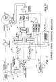
- FIG. 1 there is shown a system diagram of a fiber optic gyroscope system according to the invention.
- a fiber optic coil 10 is wound on a spool with a typical length of the optical fiber coil on the order of 100 meters to 2000 meters.
- Electromagnetic (light) waves which propagate in opposite directions through coil 10 are provided from a light source 11.
- This light source is typically a broad-line width ( ⁇ 20 nm) superradiant (sometimes called superluminescent) diode, typically emitting in the near-infrared portion of the spectrum (for example at a wavelength of 830 nm to 1500 nm).
- optical path arrangement formed by an extension of the ends of coil 10 to several optical coupling components 12, 13, 14, 15, 16, 17, 18 and 20 to be described below.
- a portion of the same kind of polarization-maintaining optical fiber as in coil 10 is positioned at source 11 to receive the light emission therefrom and extends to a first port of an optical directional coupler 12.
- Optical directional coupler 12 is of a type which has four ports, two on each end.
- a further optical fiber positioned against it and which extends to be positioned against a photodiode 13 which is electrically connected to a photodiode system 14.
- the photodiode 13 detects the light waves impinging thereon from the adjacent optical fiber and propagating from the coupler 12, and provides a photocurrent, which is a function of the impinging radiation.
- Optical directional coupler 12 has another optical fiber against a port at the other end thereof which extends to a polarizer 15. At the other port on that same side of coupler 12 there is a nonreflective termination 16 including another portion of an optical fiber.
- Directional optical coupler 12 in receiving light waves in any of its ports transmits such light so that approximately half appears at each of the two ports of coupler 12 on the end thereof opposite that end having the incoming port. No light is transmitted to the port which is on the same end of the coupler 12 as is the incoming light port.
- Polarizer 15 has a port on either end thereof with light transmission media continued therein. Positioned against the port on the opposite end thereof opposite that connected to optical directional coupler 12 is another optical fiber portion which extends to a further optical bidirectional coupler 17 which has the same light transmission properties as does coupler 12.
- the other port on the same end of coupler 17 from which a port is coupled to polarizer 15 is connected in a non-reflective termination 18 using a further optical fiber section.
- the two ports on the other end of coupler 17 one is directly coupled to one end of the optical fiber in coil 10.
- the other port is connected to a phase modulator 20 in the optical path extending to the other end of the optical fiber in coil 10.
- the phase modulator 20 has two ports, one on either end of transmission media contained therein.
- the optical fiber from coil 10 is positioned against one port of phase modulator 20 and the optical fiber extending from coupler 17 is positioned against the opposite port to complete the optical path followed by light waves from source 11.
- the phase modulator, loop coupler and polarizer can take the form of a multifunction integrated optic chip if desired.
- Phase modulator 20 is capable of receiving electrical signals from the phase difference controller to cause it to introduce a phase difference in light transmitted therethrough by changing the index of refraction of the transmission media therein to change the optical path length.
- Coupler 17 serves as a beam-splitter in that the light entering the port thereof received from polarizer 15 splits in half with one portion thereof passing out of each of the two ports on the opposite end. From the one port light passes through coil 10, through modulator 20 and back to coupler 17. There a portion of that returning light is lost in non-reflective arrangement 18, but the rest of that light passes through the other port of coupler 17 to polarizer 15 and to coupler 12 where a portion of it is transmitted to photodiode 13.
- Photodiode 13 provides an output photocurrent proportional to the intensity of the two light waves impinging thereon to the phase difference controller circuit.
- the output photocurrent depends on the resulting optical intensity of the two waves incident on photodiode 13, which intensity will vary depending on the degree of constructive or destructive interference which occurs between the two light waves. This interference of waves will change with rotation of the coiled optical fiber 10 about its axis as such rotation introduces a phase difference between the waves.
- FIG. 1 shows in block diagram form a novel electrical system portion which forms a phase difference controller feedback loop from photodiode 13 to the optical path at optical phase modulator 20.
- the output signal from photodetector system 14, including photodiode 13 is provided to a transimpedance amplifier 22, where it is amplified and passed to a phase sensitive demodulator (PSD) 24 serving as a phase detector.
- PSD phase sensitive demodulator
- the PSD provides an indication of the relative phase of light waves impinging on the photodiode 13.
- Integrator 25 receives the output of PSD 24 and stores all error excursions at the output of the PSD and provides a countering output signal based upon the time integral of those errors.
- the integrator output signal causes a sufficient phase shift in the optical path through modulator 20 to provide zero error, or zero phase difference in the steady state resulting from a constant rotation rate.
- the output signal from the integrator 25 is applied to the inputs of a positive serrodyne generator 26 and a negative serrodyne generator 27.
- the generator 26 comprises a voltage controlled oscillator (VCO) 31 and an "up" counter 33.
- the generator 27 comprises an inverter 32′, a voltage controlled oscillator 32 and a "down" counter 34. Initial frequencies of both of the VCO's may be at 15 MHz, for example.
- the output of the two counters 33 and 34 is connected to the inputs of an 8-bit adder means 35.
- the adder means may comprise an adder or may comprise an adder #1 followed by an adder #2.
- the output of the adder means is connected to a digital-to-analog converter (DAC) 40.
- the output of the DAC 40 is connected through an amplifier 41 to the phase modulator 20.
- the bias modulator 21 provides proper signals to the PSD 24 and to the adder #2. If adder #2 is not included then the bias modulator signal is instead summed at summing amplifier 41.
- a strobe circuit 42 is connected to the DAC 40 to strobe the DAC anytime a transition occurs.
- the operation of the electrical circuit operates as follows.
- the output of the integrator 25 which is nonzero when the gyro is rotated, is fed with opposite polarity to VCO 32 compared to VCO 31. This results in VCO 31 outputting a higher frequency than VCO 32.
- counter 33 counts sequentially up faster than counter 34 counts sequentially down.
- the binary words out of the counters 33 and 34 ( ⁇ u (t), ⁇ a (t)) are applied to adder #1.
- the output of adder #1 ( ⁇ 1(t)) is summed with the binary square wave modulation (w b (t)) in adder #2.
- the output of adder #2 ( ⁇ 2(t)) is converted in the digital-to-analog converter 40 to the analog serrodyne signal ⁇ 3(t). Amplification is normally required with the more customary serrodyne signal ⁇ (t) being applied to the phase modulator 20. Loop closure obtains since a phase ramp with the proper slope is applied.
- FIG. 3 there are shown symbolic waveforms of the up-counter 33 digital output, the down-counter 34 digital output and the adder 35 digital output into the digital-to-analog converter (DAC) 40.
- the waveforms are referred to as symbolic because it will be appreciated that the serrodyne signals are digital words until the final digital to analog conversion.
- the equivalent analog signal is shown for representation only.
- the up and down counters may preferably be 8-bit (or higher) counters, however in the representative waveforms A, B and C of Figure 3 a 3-bit digital synthetic serrodyne system has been shown.
- waveform A representing the "up" counter output, the progressive eight bits in the count from 000 up through 111 are shown and repeated five times.
- waveform B representing the down counter output
- the progressive eight bits stepping downward are shown and repeated about three times.
- These two counter outputs are added together in the adder means 35 and wavef orm C represents the adder means digital output into the DAC 40.
- the strobe circuit 42 causes the DAC to convert anytime an event occurs in the VCO's or bias modulation.
- This DAC timing pulse which is necessarily of short duration, strobes the DAC the minimum times needed in order to prevent extra DAC glitches.
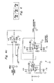
- Figure 2 shows an embodiment having two adders with the outputs of the counters 33 and 34 feeding the adder #1.
- the output of the adder #1 feeds one input of adder #2 and a bias modulation signal is inputted to the other input of adder #2, however, it is possible to eliminate adder #2 and the digital squarewave modulation.
- the bias which can be sinusoidal or squarewave is summed into the amplifier 41 as shown in the embodiment of Figure 1.
- This bias modulation can be applied in several equivalent ways using our basic approach.
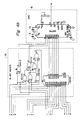
- Figure 4 comprising Figs. 4a, b and c is one example of a schematic diagram of part of the electrical portion of the block diagram of Figure 1.
- Figure 4 includes a schematic of the VCO1 and VCO2, the up counter 33, the down counter 34, the 8-bit adder 35, the digital-to-analog converter 40 and the summing amplifier 41. Each of these sections of the circuit has been outlined with dashed line enclosures and numbered the same as in Figure 1.
Landscapes
- Engineering & Computer Science (AREA)
- Physics & Mathematics (AREA)
- Power Engineering (AREA)
- Optics & Photonics (AREA)
- Electromagnetism (AREA)
- General Physics & Mathematics (AREA)
- Radar, Positioning & Navigation (AREA)
- Remote Sensing (AREA)
- Gyroscopes (AREA)
Applications Claiming Priority (2)
| Application Number | Priority Date | Filing Date | Title |
|---|---|---|---|
| US39100289A | 1989-08-09 | 1989-08-09 | |
| US391002 | 1989-08-09 |
Publications (2)
| Publication Number | Publication Date |
|---|---|
| EP0412468A1 true EP0412468A1 (de) | 1991-02-13 |
| EP0412468B1 EP0412468B1 (de) | 1994-03-30 |
Family
ID=23544821
Family Applications (1)
| Application Number | Title | Priority Date | Filing Date |
|---|---|---|---|
| EP19900115015 Expired - Lifetime EP0412468B1 (de) | 1989-08-09 | 1990-08-04 | Synthetische Sägezahnsteuerung für Faserkreisel |
Country Status (4)
| Country | Link |
|---|---|
| EP (1) | EP0412468B1 (de) |
| JP (1) | JPH0378613A (de) |
| CA (1) | CA2020379C (de) |
| DE (1) | DE69007704T2 (de) |
Cited By (2)
| Publication number | Priority date | Publication date | Assignee | Title |
|---|---|---|---|---|
| WO1997024580A1 (en) * | 1995-12-29 | 1997-07-10 | Honeywell Inc. | Coherent pickup error cancellation device |
| CN109974684A (zh) * | 2019-04-03 | 2019-07-05 | 北京航空航天大学 | 一种超高精度干涉式光纤陀螺仪的信号处理方法及装置 |
Citations (2)
| Publication number | Priority date | Publication date | Assignee | Title |
|---|---|---|---|---|
| DE3104786A1 (de) * | 1981-02-11 | 1982-09-02 | Licentia Patent-Verwaltungs-Gmbh, 6000 Frankfurt | "verfahren und anordnung zur messung absoluter drehungen" |
| EP0359666A1 (de) * | 1988-09-14 | 1990-03-21 | Photonetics S.A. | Fiberoptische Messeinrichtung, Gyrometer, Navigations- und Stabilisationssystem |
-
1990
- 1990-07-04 CA CA 2020379 patent/CA2020379C/en not_active Expired - Fee Related
- 1990-08-01 JP JP20261190A patent/JPH0378613A/ja active Pending
- 1990-08-04 EP EP19900115015 patent/EP0412468B1/de not_active Expired - Lifetime
- 1990-08-04 DE DE1990607704 patent/DE69007704T2/de not_active Expired - Fee Related
Patent Citations (2)
| Publication number | Priority date | Publication date | Assignee | Title |
|---|---|---|---|---|
| DE3104786A1 (de) * | 1981-02-11 | 1982-09-02 | Licentia Patent-Verwaltungs-Gmbh, 6000 Frankfurt | "verfahren und anordnung zur messung absoluter drehungen" |
| EP0359666A1 (de) * | 1988-09-14 | 1990-03-21 | Photonetics S.A. | Fiberoptische Messeinrichtung, Gyrometer, Navigations- und Stabilisationssystem |
Cited By (3)
| Publication number | Priority date | Publication date | Assignee | Title |
|---|---|---|---|---|
| WO1997024580A1 (en) * | 1995-12-29 | 1997-07-10 | Honeywell Inc. | Coherent pickup error cancellation device |
| CN109974684A (zh) * | 2019-04-03 | 2019-07-05 | 北京航空航天大学 | 一种超高精度干涉式光纤陀螺仪的信号处理方法及装置 |
| CN109974684B (zh) * | 2019-04-03 | 2019-12-27 | 北京航空航天大学 | 一种超高精度干涉式光纤陀螺仪的信号处理方法及装置 |
Also Published As
| Publication number | Publication date |
|---|---|
| CA2020379C (en) | 2001-01-16 |
| JPH0378613A (ja) | 1991-04-03 |
| DE69007704T2 (de) | 1994-08-11 |
| CA2020379A1 (en) | 1991-02-10 |
| DE69007704D1 (de) | 1994-05-05 |
| EP0412468B1 (de) | 1994-03-30 |
Similar Documents
| Publication | Publication Date | Title |
|---|---|---|
| US5090810A (en) | Ring resonator gyroscope controlling two servo control loops based on the output of a single interference detector | |
| JPH03210417A (ja) | ファイバー光測定装置、ジャイロメータ、セントラルナビゲーション、及び安定化システム | |
| JP3990450B2 (ja) | 光ファイバ感知コイル用の固有周波数トラッカ | |
| US5349441A (en) | Fiber optic gyroscope refractive index induced error compensation | |
| US5018859A (en) | Fiber optic gyroscope balanced plural serrodyne modulators phase difference control | |
| EP0431474B1 (de) | Optischer Faserkreisel | |
| US4382681A (en) | Measurement of rotation rate using Sagnac effect | |
| US4717256A (en) | Fiber optic rate sensor | |
| JP2780141B2 (ja) | 固有周波数位相シフトコントロールループ | |
| EP0511684B1 (de) | Phasenmodulierter faseroptischer Kreisel | |
| US20030169428A1 (en) | Saw tooth bias modulation and loop closure for an interferometric fiber optic gyroscope | |
| JP2819434B2 (ja) | 光フアイバジヤイロスコープが組合わせた信号の位相差制御装置 | |
| EP0412468B1 (de) | Synthetische Sägezahnsteuerung für Faserkreisel | |
| US5182611A (en) | Digital synthetic serrodyne for fiber optic gyroscope | |
| US4998822A (en) | Rotation rate nulling servo and method for fiber optic rotation sensor | |
| US5098188A (en) | Method and apparatus for eliminating kerr effects in a ring gyro | |
| US4906096A (en) | Apparatus and method for phase modulating optical signals in a fiber optic rotation sensor | |
| EP0565603B1 (de) | Amplitudenbestimmung der bias-modulation in einem optischen faserkreisel | |
| EP0501461B1 (de) | Optischer Faserkreisel | |
| JPS6212811A (ja) | 光干渉角速度計 | |
| RU2160885C1 (ru) | Способ стабилизации масштабного коэффициента волоконно-оптического гироскопа | |
| EP0946858B1 (de) | Genauigkeit eines faseroptischen kreisels | |
| RU2194246C1 (ru) | Способ обработки сигнала кольцевого интерферометра волоконно-оптического гироскопа | |
| JP2619015B2 (ja) | 光ファイバジャイロ | |
| RU2194247C1 (ru) | Способ фазовой модуляции в кольцевом интерферометре волоконно-оптического гироскопа |
Legal Events
| Date | Code | Title | Description |
|---|---|---|---|
| PUAI | Public reference made under article 153(3) epc to a published international application that has entered the european phase |
Free format text: ORIGINAL CODE: 0009012 |
|
| AK | Designated contracting states |
Kind code of ref document: A1 Designated state(s): DE FR GB IT SE |
|
| 17P | Request for examination filed |
Effective date: 19910201 |
|
| 17Q | First examination report despatched |
Effective date: 19911028 |
|
| GRAA | (expected) grant |
Free format text: ORIGINAL CODE: 0009210 |
|
| AK | Designated contracting states |
Kind code of ref document: B1 Designated state(s): DE FR GB IT SE |
|
| REF | Corresponds to: |
Ref document number: 69007704 Country of ref document: DE Date of ref document: 19940505 |
|
| ET | Fr: translation filed | ||
| PGFP | Annual fee paid to national office [announced via postgrant information from national office to epo] |
Ref country code: SE Payment date: 19940620 Year of fee payment: 5 |
|
| ITF | It: translation for a ep patent filed | ||
| EAL | Se: european patent in force in sweden |
Ref document number: 90115015.1 |
|
| PLBE | No opposition filed within time limit |
Free format text: ORIGINAL CODE: 0009261 |
|
| STAA | Information on the status of an ep patent application or granted ep patent |
Free format text: STATUS: NO OPPOSITION FILED WITHIN TIME LIMIT |
|
| 26N | No opposition filed | ||
| PG25 | Lapsed in a contracting state [announced via postgrant information from national office to epo] |
Ref country code: SE Effective date: 19950805 |
|
| EUG | Se: european patent has lapsed |
Ref document number: 90115015.1 |
|
| PGFP | Annual fee paid to national office [announced via postgrant information from national office to epo] |
Ref country code: GB Payment date: 20010629 Year of fee payment: 12 |
|
| PGFP | Annual fee paid to national office [announced via postgrant information from national office to epo] |
Ref country code: FR Payment date: 20010802 Year of fee payment: 12 |
|
| PGFP | Annual fee paid to national office [announced via postgrant information from national office to epo] |
Ref country code: DE Payment date: 20010831 Year of fee payment: 12 |
|
| REG | Reference to a national code |
Ref country code: GB Ref legal event code: IF02 |
|
| PG25 | Lapsed in a contracting state [announced via postgrant information from national office to epo] |
Ref country code: GB Free format text: LAPSE BECAUSE OF NON-PAYMENT OF DUE FEES Effective date: 20020804 |
|
| PG25 | Lapsed in a contracting state [announced via postgrant information from national office to epo] |
Ref country code: DE Free format text: LAPSE BECAUSE OF NON-PAYMENT OF DUE FEES Effective date: 20030301 |
|
| GBPC | Gb: european patent ceased through non-payment of renewal fee |
Effective date: 20020804 |
|
| PG25 | Lapsed in a contracting state [announced via postgrant information from national office to epo] |
Ref country code: FR Free format text: LAPSE BECAUSE OF NON-PAYMENT OF DUE FEES Effective date: 20030430 |
|
| REG | Reference to a national code |
Ref country code: FR Ref legal event code: ST |
|
| PG25 | Lapsed in a contracting state [announced via postgrant information from national office to epo] |
Ref country code: IT Free format text: LAPSE BECAUSE OF NON-PAYMENT OF DUE FEES;WARNING: LAPSES OF ITALIAN PATENTS WITH EFFECTIVE DATE BEFORE 2007 MAY HAVE OCCURRED AT ANY TIME BEFORE 2007. THE CORRECT EFFECTIVE DATE MAY BE DIFFERENT FROM THE ONE RECORDED. Effective date: 20050804 |
|
| P01 | Opt-out of the competence of the unified patent court (upc) registered |
Effective date: 20230525 |