EP0412344B1 - Device for withdrawing the thread-end from the surface of cops - Google Patents
Device for withdrawing the thread-end from the surface of cops Download PDFInfo
- Publication number
- EP0412344B1 EP0412344B1 EP90114033A EP90114033A EP0412344B1 EP 0412344 B1 EP0412344 B1 EP 0412344B1 EP 90114033 A EP90114033 A EP 90114033A EP 90114033 A EP90114033 A EP 90114033A EP 0412344 B1 EP0412344 B1 EP 0412344B1
- Authority
- EP
- European Patent Office
- Prior art keywords
- hunting
- cop
- yarn
- sensor
- winding
- Prior art date
- Legal status (The legal status is an assumption and is not a legal conclusion. Google has not performed a legal analysis and makes no representation as to the accuracy of the status listed.)
- Expired - Lifetime
Links
- 238000004804 winding Methods 0.000 claims description 55
- 230000004888 barrier function Effects 0.000 claims description 10
- 238000001514 detection method Methods 0.000 claims description 5
- 238000012544 monitoring process Methods 0.000 claims description 2
- 238000002360 preparation method Methods 0.000 description 15
- 238000000034 method Methods 0.000 description 5
- 238000007378 ring spinning Methods 0.000 description 4
- 230000000149 penetrating effect Effects 0.000 description 3
- 230000003111 delayed effect Effects 0.000 description 2
- 230000005540 biological transmission Effects 0.000 description 1
- 239000000969 carrier Substances 0.000 description 1
- 230000001419 dependent effect Effects 0.000 description 1
- 230000000694 effects Effects 0.000 description 1
- 238000004519 manufacturing process Methods 0.000 description 1
- 239000000463 material Substances 0.000 description 1
- 238000003860 storage Methods 0.000 description 1
Images


Classifications
-
- B—PERFORMING OPERATIONS; TRANSPORTING
- B65—CONVEYING; PACKING; STORING; HANDLING THIN OR FILAMENTARY MATERIAL
- B65H—HANDLING THIN OR FILAMENTARY MATERIAL, e.g. SHEETS, WEBS, CABLES
- B65H67/00—Replacing or removing cores, receptacles, or completed packages at paying-out, winding, or depositing stations
- B65H67/08—Automatic end-finding and material-interconnecting arrangements
- B65H67/086—Preparing supply packages
-
- B—PERFORMING OPERATIONS; TRANSPORTING
- B65—CONVEYING; PACKING; STORING; HANDLING THIN OR FILAMENTARY MATERIAL
- B65H—HANDLING THIN OR FILAMENTARY MATERIAL, e.g. SHEETS, WEBS, CABLES
- B65H2701/00—Handled material; Storage means
- B65H2701/30—Handled filamentary material
- B65H2701/31—Textiles threads or artificial strands of filaments
Definitions
- the invention relates to a device for releasing the rear winding thread from the surface of cops according to the preamble of the first claim.
- the cop production it is customary, for example on ring spinning machines, to form a rear winding with the end of the yarn, which runs from the tip of the head towards the cop base.
- the ring bench is moved relatively quickly from top to bottom, for example, when spindles are already running out.
- the back winding can end in a reserve winding at the base of the sleeve.
- this reserve winding is no longer present in the case of fully automatic doffing processes on the ring spinning machines.
- the reserve and / or backwinding thread is first loosened by a suction tube cutter, then the beginning of the thread is wound on the surface of the bobbin and then searched for on the entire bobbin surface by means of a suction slot arranged in a suction tube Slit led to the next station, cut there and placed in the head sleeve.
- Such devices are very expensive. In particular, due to the high air consumption, there is a considerable energy requirement.
- the US-PS 26 75 971 also describes a preparation device for cops that are fed to the winding units of a winding machine.
- the rear winding is loosened by means of a suction slot arranged along a suction tube by means of a hook formed from a bent wire.
- This hook is mounted in a hinge and is also displaced parallel to the longitudinal axis of the cops by the thread pull of the detected thread, thereby preventing the hook from penetrating into the thread layers.
- the hook is in engagement with the cop surface until the cop has moved a certain amount along the transport route.
- the hook grasps the rear winding thread immediately after it has come into contact with the surface of the cop, it pulls the thread part running in the direction of the tip of the head tightly onto the surface of the winding of the cop. It is also to be expected that the detected thread will break relatively late due to the downward movement of the hook, as a result of which additional relatively flat, very firm turns will be applied to the surface of the cop. The detection of the thread by subsequent devices is thus made considerably more difficult.
- a cop preparation device in which one or more thread looseners are present in a station of this device, which can be applied to a cop positioned on the transport route. Means for rotating the cop in the thread winding direction are also present in order to bring the thread loosener in the form of a finder knife under the rear winding. Also with this device, there is the possibility already described in connection with US Pat. No. 2,675,971 that additional, relatively flat and very strong turns which are no longer detectable in a subsequent device are applied to the cop surface after the winding thread is detected when the cop is rotated further are. The treatment time on this device must be set so high that the rear winding is released with as many cops as possible. This results in an unnecessary time delay in the event that the rear winding is detected early by the respective finder knife.
- the object of the invention is to propose a device for loosening the thread on the surface of cops, which has a high efficiency.
- the arrangement of a sensor which detects when the detected winding thread slides onto the thread loosener designed as a finder knife, makes it possible to initiate further steps directly via command signals.
- the shape of the finder knife ensures a gentler treatment of the cop surface compared to the known hook consisting of a bent wire.
- this drive can also be deactivated by a command signal generated by the sensor.
- the arrangement of a finder guide in the area of the finder knife also has an advantageous effect on the protection of the cop surface, since the finder knife is positioned exactly and is prevented from penetrating into the thread turns.
- the sensors are advantageously formed by light barriers, which consist of different arrangements of light sources and photocells.
- the thread sliding onto the finder knife breaks through the respective light barrier at one or more points.
- the success rate of cop preparation can be further increased if several finder knives that come into operation one after the other are arranged one above the other. After the sensor arranged at the lowest finder knife has recognized the thread, this finder knife is lifted from the surface of the cop and the finder knife arranged above it is pivoted to the surface of the cop. This prevents the thread from first tearing through the upper finder knife when the rear winding thread is detected, and the lower part of the rear winding remains on the outer surface of the cop, which can subsequently lead to considerable difficulties during the winding process.
- the beginning of the thread is placed loosely on the upper part of the bobbin surface, which makes it very easy to loosen the beginning of the thread in the area of the winding point, for example, if the thread from the winding point
- the bobbin surface is released by an upward air flow surrounding the bobbin and fed to a feeder device.
- the additional arrangement of a suction nozzle in the region of the bobbin foot of the preparation device according to the invention may be necessary. In this case, however, the switching off of the drive for the bobbin rotation would have to be delayed after the sensor recognizes the winding thread. If several finder knives are arranged one above the other, it may be sufficient if the cop is rotated until the upper finder knife has also grasped the remaining part of the rear winding.
- a cop 3 is fed upright on the arbor of a pallet 1 on the conveyor belt 5 of a conveyor track 2 of a preparation device according to the invention and positioned there.
- the pallet 1 is guided along the transport path 2 by guide plates 6 and 6 '.
- the Arrival of a pallet 1 is reported by a sensor 28 via a control line 28 'to a central control unit 60 which actuates a rotary solenoid 27 via a control line 27'.
- a pivot rod 14 is rotated counterclockwise by the rotary solenoid 27.
- a roller holder 13 with pressure roller 12 is also pivoted in such a way that the pressure roller 12 bears against the base plate 1 'of the pallet 1.
- the guide plate 6 has a recess 7.
- the pressure roller 12 presses the base plate 1 'of the pallet 1 against two pulleys 11 on the opposite side of the transport path 2, of which only one can be seen in FIG. 1.
- a recess 7 ' is provided in the opposite guide plate 6'.
- the flat belt 10 is driven by a motor 9 via a drive roller 8.
- the motor 9 receives its control command signals from the central control unit 60 via a control line 9 ′.
- the plate 61 on which both pulleys 11 and the drive roller 8 are mounted can also be pivoted. It is pivoted in synchronism with the swivel rod 14 and thus with the roll holder 13 for positioning the pallet.
- a bracket 41 is also attached to the pivot rod 14 by means of a bracket 42 by means of a fastening screw 43. After swiveling the bracket presses so against the sleeve tip 3 'of the cop 3 that it is tilted slightly against the tilting direction of the pallet 1, whereby the frictional force on the Pallet 1 mandrel increased. As a result, the rotational movement from the driven pallet 1 is also transmitted to the cop 3 in the direction of the arrow 4 when it is not seated tightly on the arbor.
- an adjusting screw 44 it is possible to adjust the height of the bracket 41 to different cop lengths.
- the angular position of the bracket 41 can be changed either by means of the fastening screw 43 or the adjusting screw 44.
- the lower finder guide 15 is rotatably mounted in a holder 23 by means of a pivot pin 21.
- the bracket 23 is fastened to the swivel rod 14 by means of a fastening screw 25.
- the finder knife 16 is attached to the finder guide 15 with fastening screws 19.
- 15 elongated holes can be provided in the finder guide, in which the fastening screws 19 can be displaced, as a result of which the finder knife 16 can be adjusted according to the scope diameter.
- a pivot lever 29 is attached on the viewfinder guide 15 opposite side of the pivot pin 21, a pivot lever 29 is attached.
- This pivot lever 29 is connected to the piston 31 of a pneumatic cylinder 33 via a swivel joint 29 '.
- This cylinder 33 is fastened to the swivel lever 14 via a holder 39.
- Air lines 35 and 36 open at the two ends of the pneumatic cylinder 33. These air lines 35 and 36 are connected to a compressed air source, not shown. They can be pressurized with compressed air alternately via valves, also not shown. The valves are controlled via the central control unit 60.
- the piston 31 is shifted to the left.
- the viewfinder guide 15 is pivoted clockwise by the transmission via the pivot joint 29 ', pivot lever 29 and pivot pin 21.
- the finder knife 16 lifts off the surface of the cop. This process is initiated after the rear winding thread 47, which is picked up by the finder knife 16 and pushed onto its back, has interrupted the light barrier formed by a light source 48 and a photodiode 49.
- the photodiode 49 has a connection 49 'to the central control unit 60, which then opens the valve leading to the air line 35.
- a further viewfinder guide 17 with viewfinder knife 18 is attached to the pivot rod 14.
- the structure corresponds to that of the lower arrangement of the finder guide 15.
- the finder knife 18 with fastening screws 20 is fastened to the finder guide 17 analogously to the finder knife 16.
- At the end of the finder guide 17 there is also a pivot pin 22 which is connected on the opposite side to a pivot lever 30 which in turn has a pivot joint 30 '.
- the swivel joint 30 ' is connected to a piston 32 which is guided in a pneumatic cylinder 34.
- the pneumatic cylinder 34 is fastened to the swivel lever 14 by means of a holder 40.
- Air lines 37 and 38 are arranged at the two ends of the pneumatic cylinder 34 and are also connected to a compressed air source via valves, not shown.
- the pivot pin 22 is mounted in a holder 24 which is secured by a fastening screw 26 is attached to the pivot rod 14.
- the valves leading to the air lines 37 and 38 are also controlled by the central control unit 60.
- the winding thread 47 has just been recognized by the sensor formed by the light source 48 and the photodiode 49, which is why the central control unit, which has received the success signal from the sensor, opens the valve to the air line 35, thereby guiding the viewfinder 15 with the finder knife 16 off the surface of the cop.
- the valve which leads to the air line 38 is opened via the central control unit 60.
- the piston 32 is displaced to the right in the pneumatic cylinder 34, as a result of which the finder guide 17 with the finder knife 18 is pivoted to the surface of the cop. This ensures that the thread search on the upper part of the head jacket only begins when the rear winding thread 47 has been detached from the lower finder knife 16.
- the upper viewfinder guide 17 is also equipped with a sensor, the success of the thread search is also recorded there. Depending on this, the viewfinder guide 17 is then lifted off via the central control unit by a valve which leads to the air line 37.
- a swiveling suction nozzle 50 is additionally arranged.
- This suction nozzle 50 has a suction air connection 51.
- this suction nozzle 50 could also be attached directly to the swivel arm 14. It would be sufficient if the suction nozzle 50 is only pivoted to the bobbin foot when the lower finder knife 16 has gripped the winding thread 47. Because with a longer reserve winding on the cops foot in most cases If the winding thread 47 is torn, the suction nozzle 50 can grasp the lower end of the torn thread and, while maintaining the cop rotation, unwind and suck in the reserve thread.
- the central control unit 60 deactivates the motor 9, as a result of which the rotational movement of the cop 3 is stopped.
- the central unit 60 controls the rotary solenoid 27, which pivots the pivot rod 14 with all the devices attached to it in a clockwise direction, as a result of which all these devices are removed from the transport path 2.
- the plate 61 is also pivoted. As a result, the pallet 1 with cops 3 of the conveyor belt 5 is moved further in the direction of the arrow.
- the motor 9 can also be put out of operation directly by the pivoting mechanism for the finder guides 15 and 17 after reaching the end position via a switch (not shown).
- another preparation device can also be arranged on the same transport route following the device according to the invention, which, for example, searches for the thread on the entire surface of the cop by means of suction air. This device would only be active if the search for the tail thread 47 on the device according to the invention was unsuccessful.
- the central unit 60 there is a timer in which a maximum search time is stored. This ensures that even in exceptional cases, in which the finder knife 16 cannot catch the winding thread 47 quickly enough, no jam is caused on the transport path 2 by the cop positioned at the treatment station. After the maximum search time has elapsed, even if no successful thread search was indicated by the sensor, all actuating units and the components of the positioning and drive device are pivoted away from the cop 3 so that it is released again. This is necessary in order to continuously supply the bobbin with fresh cops for unwinding.
- pneumatic cylinders 33 and 34 instead of the pneumatic cylinders 33 and 34, other actuating devices can also be used, with the aid of which the finder guides 15 and 17 can be pivoted.
- rotary solenoids are conceivable, which are fastened to the brackets 23 and 24 and which rotate the rotary bolts 21 and 22 by a certain amount about their longitudinal axis on the basis of control commands from the central control unit 60.
- finder guides 15 and 17 it is also possible within the scope of the invention to replace the torsion bar 14 by a fixed bar.
- the search guides 15 and 17 are then exclusive pivoted by means of the pivot pins 21 and 22.
- the roll holder 13 then also requires a separate pivoting device.
- the rounded shape of the bracket 41 also allows it to be arranged stationary.
- the sleeve tip 3 'of the cop 3 then slides over the bracket 41 when the cop enters the preparation station, whereby the cop is also tilted in such a way that the frictional force on the mandrel of the pallet 1 increases sufficiently to prevent the pallet from rotating on the cop transferred to.
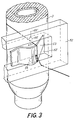
- Fig. 2 contains the variant shown in Fig. 1 in an enlarged form.
- the viewfinder guide 15 or 17 has a window 15 'or 17'.
- a viewfinder knife 16, 18 protrudes through this window.
- the wedge-shaped shape of the viewfinder knife is clearly recognizable.
- the front edge of the finder knife 16, 18 projects beyond the side of the finder guide 15, 17 facing the cop surface.
- the finder guide 15, 17 prevents the finder knife from penetrating into the thread layers of the cop 3.
- the trailing thread 47 slides on the back of the finder knife 16, 18.
- the finder knife 53 is curved so that it has a light barrier, which is formed by the light source 54 and the photodiode 55, releases within the window 52 'of the viewfinder guide 52.
- the photodiode 55 has a line 55 'which leads to the central control unit 60.
- the light barrier is interrupted by thread triangles formed between the back of the finder knife 53 and the finder guide 52.
- a light source 58 is attached to the finder knife 57 itself, which, together with the photodiode 59 attached to the finder guide 56, represents the light barrier forming the sensor.
- the winding thread 47 interrupts the light barrier when the search is successful while it is sliding open.
- the photodiode 59 has a line 59 ', via which the success of the thread search is transmitted to the central control unit 60.
Landscapes
- Replacing, Conveying, And Pick-Finding For Filamentary Materials (AREA)
- Coiling Of Filamentary Materials In General (AREA)
Description
Die Erfindung betrifft eine Vorrichtung zum Lösen des Hinterwindungsfadens von der Oberfläche von Kopsen gemäß dem Oberbegriff des ersten Anspruches.The invention relates to a device for releasing the rear winding thread from the surface of cops according to the preamble of the first claim.
Beim Beenden der Kopsherstellung ist es beispielsweise an Ringspinnmaschinen üblich, mit dem Garnende eine Hinterwindung zu bilden, die von der Kopsspitze in Richtung auf den Kopsfuß verläuft. Hierzu wird beispielsweise bei schon auslaufenden Spindeln die Ringbank verhältnismäßig rasch von oben nach unten bewegt. Die Hinterwindung kann am Hülsenfuß in einer Reservewindung enden. Diese Reservewindung ist jedoch bei vollautomatischen Doffvorgängen an den Ringspinnmaschinen nicht mehr vorhanden.At the end of the cop production, it is customary, for example on ring spinning machines, to form a rear winding with the end of the yarn, which runs from the tip of the head towards the cop base. For this purpose, the ring bench is moved relatively quickly from top to bottom, for example, when spindles are already running out. The back winding can end in a reserve winding at the base of the sleeve. However, this reserve winding is no longer present in the case of fully automatic doffing processes on the ring spinning machines.
Beim Vorbereiten derartiger Kopse für den Abspulprozeß in einer Spulmaschine kommt es darauf an, möglichst ohne Beschädigung der Oberfläche des Wickels das Garnende so freizulegen, daß es in der Abspulposition erfaßbar und den entsprechenden Aggregaten der Spulstelle vorlegbar ist.When preparing such cops for the unwinding process in a winding machine, it is important to expose the end of the yarn so as to avoid damage to the surface of the winding so that it can be detected in the unwinding position and presented to the corresponding units of the winding unit.
Vorrichtungen, die den Fadenanfang auf der Oberfläche von Kopsen suchen und dann für den Abspulvorgang an einer definierten Stelle bereitlegen, sind bereits bekannt. In den meisten dieser Vorrichtungen werden die Kopse in einer Kreisbahn an mehreren verschiedenen Behandlungsstationen vorbeigeführt, wodurch sich ein schrittweiser Vorbereitungsprozeß ergibt.Devices which search for the beginning of the thread on the surface of cops and then prepare them for the unwinding process at a defined point are already known. In most of these devices, the cops are in a circular path on several passed different treatment stations, which results in a step-by-step preparation process.
Zum Beispiel gemäß der DE-A 36 02 002 wird zuerst durch einen Saugrohrschneider der Reserve- und/oder Hinterwindungsfaden gelöst, anschließend der Fadenanfang auf die Kopsoberfläche gewickelt und darauffolgend auf der gesamten Kopsoberfläche mittels eines in einem Saugrohr angeordneten Saugschlitzes gesucht, eingesaugt, in dem Schlitz bis zu nächsten Station geführt, dort geschnitten und in die Kopshülse verbracht. Derartige Vorrichtungen sind sehr aufwendig. Insbesondere ist durch den hohen Luftverbrauch ein erheblicher Energiebedarf zu verzeichnen.For example, according to DE-A 36 02 002, the reserve and / or backwinding thread is first loosened by a suction tube cutter, then the beginning of the thread is wound on the surface of the bobbin and then searched for on the entire bobbin surface by means of a suction slot arranged in a suction tube Slit led to the next station, cut there and placed in the head sleeve. Such devices are very expensive. In particular, due to the high air consumption, there is a considerable energy requirement.
Die US-PS 26 75 971 beschreibt ebenfalls eine Vorbereitungseinrichtung für Kopse, die den Spulstellen einer Spulmaschine zugeführt werden. Dabei wird vor dem Suchen des Fadenanfanges mittels eines entlang eines Saugrohres angeordneten Saugschlitzes die Hinterwindung durch einen aus einem gebogenen Draht gebildeten Haken gelöst. Dieser Haken ist in einem Gelenk gelagert und wird durch den Fadenzug des erfaßten Fadens unter anderem auch parallel zur Kopslängsachse verlagert, wodurch ein Eindringen des Hakens in die Fadenlagen verhindert werden soll. Der Haken steht dabei mit der Kopsoberfläche solange im Eingriff, bis sich der Kops entlang der Transportstrecke um einen bestimmten Betrag weiterbewegt hat. Erfaßt der Haken den Hinterwindungsfaden unmittelbar, nachdem er Kontakt zur Kopsoberfläche bekommen hat, zieht er den in Richtung Kopsspitze verlaufenden Fadenteil straff auf die Oberfläche der Kopswindungen. Es ist auch damit zu rechnen, daß durch das Ausweichen des Hakens nach unten der erfaßte Faden relativ spät reißt, wodurch auf der Kopsoberfläche zusätzliche relativ flache, sehr feste Windungen aufgebracht werden. Das Erfassen des Fadens durch nachfolgende Einrichtungen wird damit erheblich erschwert.The US-
Durch die gattungsgemäße DE-OS 15 60 427 ist eine Kopsvorbereitungseinrichtung bekannt, bei der in einer Station dieser Einrichtung ein oder mehrere Fadenlöser vorhanden sind, die an einen auf der Transportstrecke positionierten Kops anlegbar sind. Weiterhin sind Mittel zum Drehen des Kopses in Fadenwickelrichtung vorhanden, um den Fadenlöser in Form eines Suchermessers unter die Hinterwindung zu bringen. Auch bei dieser Einrichtung besteht die bereits im Zusammenhang mit der US-PS 2,675,971 beschriebene Möglichkeit, daß nach dem Erfassen des Hinterwindungsfadens beim Weiterdrehen des Kopses zusätzliche, relativ flache und sehr feste Windungen auf der Kopsoberfläche aufgebracht werden, die in einer nachfolgenden Einrichtung nicht mehr erfaßbar sind. Die Behandlungszeit an dieser Vorrichtung muß so hoch eingestellt sein, daß bei möglichst vielen Kopsen die Hinterwindung gelöst wird. Dadurch ergibt sich eine unnötige Zeitverzögerung im Falle des frühzeitigen Erfassens der Hinterwindung durch das jeweilige Suchermesser.From the generic DE-OS 15 60 427 a cop preparation device is known in which one or more thread looseners are present in a station of this device, which can be applied to a cop positioned on the transport route. Means for rotating the cop in the thread winding direction are also present in order to bring the thread loosener in the form of a finder knife under the rear winding. Also with this device, there is the possibility already described in connection with US Pat. No. 2,675,971 that additional, relatively flat and very strong turns which are no longer detectable in a subsequent device are applied to the cop surface after the winding thread is detected when the cop is rotated further are. The treatment time on this device must be set so high that the rear winding is released with as many cops as possible. This results in an unnecessary time delay in the event that the rear winding is detected early by the respective finder knife.
Aufgabe der Erfindung ist es, eine Vorrichtung zum Lösen des Fadens auf der Oberfläche von Kopsen vorzuschlagen, die einen hohen Wirkungsgrad besitzt.The object of the invention is to propose a device for loosening the thread on the surface of cops, which has a high efficiency.
Diese Aufgabe wird erfindungsgemäß durch die Merkmale des Anspruches 1 gelöst.This object is achieved by the features of claim 1.
Die Erfindung ist durch die Merkmale der Ansprüche 2 bis 13 vorteilhaft weitergebildet.The invention is advantageously developed by the features of
Die Anordnung eines Sensors, der erkennt, wenn der erfaßte Hinterwindungsfaden auf den als Suchermesser ausgebildeten Fadenlöser aufgleitet, ermöglicht es, über Befehlssignale unmittelbar weitere Schritte einzuleiten. Durch das Abheben des Suchermessers sofort nach erkanntem Faden wird dieser gelöst oder zerrissen. Dadurch ist es nicht möglich, daß sich oberhalb des Suchermessers der Faden in straffen Windungen auf der Kopsoberfläche fixiert. Es wird außerdem vermieden, daß der bereits gelöste Faden in Höhe des Suchermessers in die Kopsoberfläche durch das Suchermesser eingebügelt wird. Dabei sichert die Form des Suchermessers gegenüber dem bekannten aus einem gebogenen Draht bestehenden Haken eine schonendere Behandlung der Kopsoberfläche.The arrangement of a sensor, which detects when the detected winding thread slides onto the thread loosener designed as a finder knife, makes it possible to initiate further steps directly via command signals. By lifting the finder knife immediately after the thread is recognized, it is loosened or torn. As a result, it is not possible for the thread to be fixed in tight turns on the surface of the cop above the finder knife. It is also avoided that the thread already loosened at the level of the finder knife is ironed into the cop surface by the finder knife. The shape of the finder knife ensures a gentler treatment of the cop surface compared to the known hook consisting of a bent wire.
Durch das lockere Ablegen des Fadenanfanges auf der Kopsoberfläche in Verbindung mit der Überwachung des Erfolges der Fadensuche und der davon abhängigen Steuerung des Kopses auf seinem weiteren Transportweg ist es möglich, in Abhängigkeit vom Fadenmaterial auf weitere Vorbereitungsstationen zu verzichten, insbesondere wenn in der Spulstelle der Faden von der Kopsoberfläche durch eine den Kops umgebende aufwärts gerichtete Luftströmung gelöst und einer Zubringereinrichtung zugeführt wird. Dabei entspricht die Erfolgswahrscheinlichkeit einer so vereinfachten Vorbereitung dem bekannter Vorbereitungseinrichtungen, die mehrere Vorbereitungsstationen aufweisen.By loosely placing the thread start on the bobbin surface in connection with monitoring the success of the thread search and the dependent control of the bobbin on its further transport path, it is possible, depending on the thread material, to dispense with further preparation stations, especially if the thread is in the winding station is released from the surface of the cop by an upward air flow surrounding the cop and is fed to a feeder device. The likelihood of success of such a simplified preparation corresponds to the familiar one Preparation facilities that have several preparation stations.
Da nach dem Erfassen und Lösen des Fadenanfanges normalerweise eine weitere Drehbewegung des Kopses nicht erforderlich ist, kann dieser Antrieb auch durch ein vom Sensor erzeugtes Befehlssignal außer Betrieb gesetzt werden.Since after the thread start has been detected and released, a further rotary movement of the cop is normally not necessary, this drive can also be deactivated by a command signal generated by the sensor.
Neben der Gestaltung des Fadenlösers als Suchermesser wirkt sich auch noch die Anordnung einer Sucherführung im Bereich des Suchermessers vorteilhaft auf die Schonung der Kopsoberfläche aus, da das Suchermesser exakt positioniert und am Eindringen in die Fadenwindungen gehindert wird.In addition to the design of the thread remover as a finder knife, the arrangement of a finder guide in the area of the finder knife also has an advantageous effect on the protection of the cop surface, since the finder knife is positioned exactly and is prevented from penetrating into the thread turns.
Die Sensoren werden vorteilhaft durch Lichtschranken gebildet, die aus verschiedenen Anordnungen von Lichtquellen und Fotozellen bestehen. Der auf das Suchermesser aufgleitende Faden durchbricht dabei an einer oder mehreren Stellen die jeweilige Lichtschranke.The sensors are advantageously formed by light barriers, which consist of different arrangements of light sources and photocells. The thread sliding onto the finder knife breaks through the respective light barrier at one or more points.
Die Erfolgsquote der Kopsvorbereitung kann weiter gesteigert werden, wenn übereinander mehrere nacheinander in Funktion tretende Suchermesser angeordnet werden. Nachdem der am untersten Suchermesser angeordnete Sensor den Faden erkannt hat, wird dieses Suchermesser von der Kopsoberfläche abgehoben und das darüber angeordnete Suchermesser an die Kopsoberfläche angeschwenkt. Dadurch wird verhindert, daß bei Erfassung des Hinterwindungsfadens zuerst durch das obere Suchermesser der Faden oben reißt und damit der untere Teil der Hinterwindung auf der Mantelfläche des Kopses verbleibt, was anschließend beim Spulprozeß zu erheblichen Schwierigkeiten führen kann. Durch das obere Suchermesser wird nach dem Lösen des unteren Teiles der Hinterwindung der Fadenanfang auf dem oberen Teil der Kopsoberfläche locker abgelegt, wodurch sich der Fadenanfang im Bereich der Spulstelle sehr leicht lösen läßt, wenn zum Beispiel in der Spulstelle der Faden von der Kopsoberfläche durch eine den Kops umgebende aufwärts gerichtete Luftströmung gelöst und einer Zubringereinrichtung zugeführt wird.The success rate of cop preparation can be further increased if several finder knives that come into operation one after the other are arranged one above the other. After the sensor arranged at the lowest finder knife has recognized the thread, this finder knife is lifted from the surface of the cop and the finder knife arranged above it is pivoted to the surface of the cop. This prevents the thread from first tearing through the upper finder knife when the rear winding thread is detected, and the lower part of the rear winding remains on the outer surface of the cop, which can subsequently lead to considerable difficulties during the winding process. Through the upper finder knife, after loosening the lower part of the rear winding, the beginning of the thread is placed loosely on the upper part of the bobbin surface, which makes it very easy to loosen the beginning of the thread in the area of the winding point, for example, if the thread from the winding point The bobbin surface is released by an upward air flow surrounding the bobbin and fed to a feeder device.
Werden an der Ringspinnmaschine im Anschluß an die Hinterwindung noch Reservewicklungen am Kopsfuß gebildet, kann die zusätzliche Anordnung einer Saugdüse im Bereich des Kopsfußes der erfindungsgemäßen Vorbereitungseinrichtung erforderlich sein. Dabei müßte allerdings das Abschalten des Antriebes für die Kopsumdrehung nach dem Erkennen des Hinterwindungsfadens durch den Sensor verzögert werden. Bei der Anordnung mehrerer Suchermesser übereinander kann es ausreichen, wenn der Kops noch so lange gedreht wird, bis das obere Suchermesser den verbleibenden Teil der Hinterwindung ebenfalls erfaßt hat.If reserve windings are formed on the bobbin foot on the ring spinning machine following the rear winding, the additional arrangement of a suction nozzle in the region of the bobbin foot of the preparation device according to the invention may be necessary. In this case, however, the switching off of the drive for the bobbin rotation would have to be delayed after the sensor recognizes the winding thread. If several finder knives are arranged one above the other, it may be sufficient if the cop is rotated until the upper finder knife has also grasped the remaining part of the rear winding.
Die Erfindung soll nachstehend anhand von Ausführungsbeispielen näher erläutert werden. In den Zeichnungen zeigen:
- Fig. 1
- eine perspektivische Gesamtansicht einer erfindungsgemäßen Vorbereitungseinrichtung,
- Fig. 2
- eine stark vergrößerte Darstellung der Einzelheit X aus Fig. 1,
- Fig. 3
- eine stark vergrößerte Darstellung einer Variante der Gestaltung des Suchermessers und
- Fig. 4
- eine weitere stark vergrößerte Darstellung einer Variante der Ausgestaltung von Suchermesser und Sucherführung.
- Fig. 1
- an overall perspective view of a preparation device according to the invention,
- Fig. 2
- 2 shows a greatly enlarged illustration of the detail X from FIG. 1,
- Fig. 3
- a greatly enlarged representation of a variant of the design of the finder knife and
- Fig. 4
- another greatly enlarged illustration of a variant of the design of the finder knife and finder guidance.
Ein Kops 3 wird aufrechtstehend auf dem Aufsteckdorn einer Palette 1 auf dem Transportband 5 einer Transportbahn 2 einer erfindungsgemäßen Vorbereitungseinrichtung zugeführt und dort positioniert. Die Führung der Palette 1 entlang der Transportbahn 2 erfolgt durch Führungsplatten 6 und 6'. Die Ankunft einer Palette 1 wird durch einen Sensor 28 über eine Steuerleitung 28' an eine zentrale Steuereinheit 60 gemeldet, die einen Drehsolenoid 27 über eine Steuerleitung 27' betätigt. Entsprechend zeitverzögert wird durch den Drehsolenoid 27 ein Schwenkstab 14 entgegen dem Uhrzeigersinn gedreht. Dabei wird auch ein Rollenhalter 13 mit Andruckrolle 12 so verschwenkt, daß sich die Andruckrolle 12 an die Grundplatte 1' der Palette 1 anlegt. Dafür weist die Führungsplatte 6 eine Aussparung 7 auf. Durch eine Gestaltung der Andruckrolle 12 als Spurkranzrolle kann außerdem die Palette 1 geringfügig gekippt werden, wodurch die Grundplatte 1' nicht mehr mit der gesamten Fläche ihrer Unterseite auf dem Transportband 5 aufliegt.A
Die Andruckrolle 12 drückt die Grundplatte 1' der Palette 1 gegen zwei Riemenscheiben 11 auf der gegenüberliegenden Seite der Transportbahn 2, von denen in Fig. 1 lediglich eine erkennbar ist. Für diese Riemenscheiben 11 mit dem Flachriemen 10 ist in der gegenüberliegenden Führungsplatte 6' eine Aussparung 7' vorgesehen. Der Flachriemen 10 wird über eine Antriebsrolle 8 durch einen Motor 9 angetrieben. Der Motor 9 erhält seine Steuerbefehlssignale über eine Steuerleitung 9' von der zentralen Steuereinheit 60.The
Da die Riemenscheiben 11 für den Antrieb der Palette 1 in die Transportbahn eindringen, ist die Platte 61, auf der beide Riemenscheiben 11 und die Antriebsrolle 8 gelagert sind, ebenfalls schwenkbar. Sie wird synchron mit dem Schwenkstab 14 und damit mit dem Rollenhalter 13 zur Positionierung der Palette angeschwenkt.Since the pulleys 11 penetrate the transport path for driving the pallet 1, the
Ein Bügel 41 ist über eine Halterung 42 mittels einer Befestigungsschraube 43 ebenfalls am Schwenkstab 14 befestigt. Nach dem Einschwenken drückt der Bügel so gegen die Hülsenspitze 3' des Kopses 3, daß dieser etwas entgegen der Kipprichtung der Palette 1 verkantet wird, wodurch sich die Reibkraft auf dem Aufsteckdorn der Palette 1 erhöht. Dadurch wird die Drehbewegung von der angetriebenen Palette 1 auch dann auf den Kops 3 in Richtung des Pfeils 4 übertragen, wenn dieser nicht straff auf dem Aufsteckdorn aufsitzt. Durch eine Justierschraube 44 ist es möglich, den Bügel 41 in seiner Höhe auf verschiedene Kopslängen einzustellen. Außerdem kann entweder mittels der Befestigungsschraube 43 oder der Justierschraube 44 die Winkelstellung des Bügels 41 verändert werden.A bracket 41 is also attached to the
Die Fig. 1 zeigt bereits eine Variante der Erfindung, bei der zwei Suchermesser 16, 18 übereinander angeordnet sind. Auch sind an beiden Sucherführungen 15 und 17 Sensorträger 45 und 46 angeordnet. Es wäre aber im Rahmen der Erfindung durchaus denkbar, lediglich ein Suchermesser 16 mit einem entsprechenden Sensor vorzusehen. Die untere Sucherführung 15 ist mittels eines Drehbolzens 21 in einer Halterung 23 drehbar gelagert. Die Halterung 23 ist mittels einer Befestigungsschraube 25 am Schwenkstab 14 befestigt. Das Suchermesser 16 ist mit Befestigungsschrauben 19 an der Sucherführung 15 angebracht. Dabei können in der Sucherführung 15 Langlöcher vorgesehen sein, in denen die Befestigungsschrauben 19 verschiebbar sind, wodurch sich das Suchermesser 16 entsprechend dem Kopsdurchmesser justieren läßt.1 already shows a variant of the invention in which two
Auf der der Sucherführung 15 gegenüberliegenden Seite des Drehbolzens 21 ist ein Schwenkhebel 29 befestigt. Dieser Schwenkhebel 29 ist über ein Drehgelenk 29' mit dem Kolben 31 eines Pneumatikzylinders 33 verbunden. Dieser Zylinder 33 ist über eine Halterung 39 am Schwenkhebel 14 befestigt. An den beiden Enden des Pneumatikzylinders 33 münden Luftleitungen 35 und 36. Diese Luftleitungen 35 und 36 sind mit einer nicht dargestellten Druckluftquelle verbunden. Sie sind über ebenfalls nicht dargestellte Ventile wechselseitig mit Druckluft beaufschlagbar. Die Ansteuerung der Ventile erfolgt über die zentrale Steuereinheit 60.On the viewfinder guide 15 opposite side of the
Wird zum Beispiel das Ventil geöffnet, welches die Druckluftquelle mit der Luftleitung 35 verbindet, so wird der Kolben 31 nach links verschoben. Durch die Übertragung über Drehgelenk 29', Schwenkhebel 29 und Drehbolzen 21 wird die Sucherführung 15 im Uhrzeigersinn verschwenkt. Dadurch hebt das Suchermesser 16 von der Kopsoberfläche ab. Dieser Vorgang wird eingeleitet, nachdem der vom Suchermesser 16 erfaßte und auf dessen Rücken aufgeschobene Hinterwindungsfaden 47 die durch eine Lichtquelle 48 und eine Fotodiode 49 gebildete Lichtschranke unterbrochen hat. Die Fotodiode 49 weist eine Verbindung 49' zur zentralen Steuereinheit 60 auf, die dann das zur Luftleitung 35 führende Ventil öffnet. Auf diese Weise wird gewährleistet, daß sofort nach dem Erfassen des Hinterwindungsfadens 47 das Suchermesser 16 von der Kopsoberfläche abhebt, wodurch der Hinterwindungsfaden 47 vom Kopsfuß gelöst oder auch zerrissen wird. Dadurch wird ein Einbügeln des Hinterwindungsfadens 47 in die Kopsoberfläche in Höhe der Sucherführung 15 vermieden.For example, if the valve that connects the compressed air source to the
Wie in der Fig. 1 dargestellt, ist noch eine weitere Sucherführung 17 mit Suchermesser 18 am Schwenkstab 14 befestigt. Der Aufbau entspricht dem der unteren Anordnung der Sucherführung 15. Das Suchermesser 18 mit Befestigungsschrauben 20 ist an der Sucherführung 17 analog dem Suchermesser 16 befestigt. Am Ende der Sucherführung 17 ist ebenfalls ein Drehbolzen 22 angeordnet, der auf der gegenüberliegenden Seite mit einem Schwenkhebel 30 verbunden ist, der seinerseits ein Drehgelenk 30' aufweist. Das Drehgelenk 30' ist mit einem Kolben 32 verbunden, der in einem Pneumatikzylinder 34 geführt ist. Der Pneumatikzylinder 34 ist mittels einer Halterung 40 am Schwenkhebel 14 befestigt. An den beiden Enden des Pneumatikzylinders 34 sind Luftleitungen 37 und 38 angeordnet, die ebenfalls über nicht dargestellte Ventile mit einer Druckluftquelle verbunden sind. Der Drehbolzen 22 ist in einer Halterung 24 gelagert, die durch eine Befestigungsschraube 26 am Schwenkstab 14 befestigt ist. Die zu den Luftleitungen 37 und 38 führenden Ventile werden ebenfalls von der zentralen Steuereinheit 60 angesteuert.As shown in FIG. 1, a further viewfinder guide 17 with
In der Darstellung gemäß Fig. 1 ist soeben vom durch die Lichtquelle 48 und die Fotodiode 49 gebildeten Sensor der Hinterwindungsfaden 47 erkannt worden, weshalb von der zentralen Steuereinheit, die das Erfolgssignal vom Sensor empfangen hat, das Ventil zur Luftleitung 35 geöffnet wird, wodurch Sucherführung 15 mit Suchermesser 16 von der Kopsoberfläche abheben. Gleichzeitig wird über die zentrale Steuereinheit 60 das Ventil geöffnet, welches zur Luftleitung 38 führt. Dadurch wird im Pneumatikzylinder 34 der Kolben 32 nach rechts verschoben, wodurch die Sucherführung 17 mit Suchermesser 18 an die Kopsoberfläche geschwenkt wird. Dadurch wird sichergestellt, daß die Fadensuche am oberen Teil des Kopsmantels erst dann einsetzt, wenn der Hinterwindungsfaden 47 vom unteren Suchermesser 16 gelöst wurde.In the illustration according to FIG. 1, the winding
Da im vorliegenden Fall auch die obere Sucherführung 17 mit einem Sensor ausgerüstet ist, wird auch dort der Erfolg der Fadensuche erfaßt. In Abhängigkeit davon wird dann über die zentrale Steuereinheit durch ein Ventil, welches zur Luftleitung 37 führt, das Abheben der Sucherführung 17 eingeleitet.Since in the present case the upper viewfinder guide 17 is also equipped with a sensor, the success of the thread search is also recorded there. Depending on this, the viewfinder guide 17 is then lifted off via the central control unit by a valve which leads to the
Für den Fall, daß am Kopsfuß 3'' an der Ringspinnmaschine noch eine zusätzliche Reservewindung aufgebracht wurde, ist eine schwenkbare Saugdüse 50 zusätzlich angeordnet. Diese Saugdüse 50 besitzt einen Saugluftanschluß 51. In Abweichung zur Darstellung in Fig. 1 könnte diese Saugdüse 50 auch direkt am Schwenkarm 14 angebracht sein. Dabei wäre es ausreichend, wenn die Saugdüse 50 erst dann an den Kopsfuß geschwenkt wird, wenn das untere Suchermesser 16 den Hinterwindungsfaden 47 erfaßt hat. Da bei einer längeren Reservewicklung am Kopsfuß in den meisten Fällen der Hinterwindungsfaden 47 zerrissen wird, kann die Saugdüse 50 das untere Ende des gerissenen Fadens erfassen und bei Beibehaltung der Kopsdrehung die Reservewindung abwickeln und einsaugen.In the event that an additional reserve thread has been applied to the cops foot 3 ″ on the ring spinning machine, a swiveling
Nach dem Abschwenken der oberen Sucherführung 17 von der Kopsoberfläche wird von der zentralen Steuereinheit 60 der Motor 9 außer Betrieb gesetzt, wodurch die Drehbewegung des Kopses 3 gestoppt wird. Anschließend steuert die Zentraleinheit 60 den Drehsolenoid 27 an, der den Schwenkstab 14 mit allen an ihm befestigten Einrichtungen im Uhrzeigersinn verschwenkt, wodurch alle diese Einrichtungen aus der Transportbahn 2 entfernt werden. Ebenso wird die Platte 61 verschwenkt. Dadurch wird die Palette 1 mit Kops 3 von Transportband 5 weiter in Pfeilrichtung bewegt.After the upper viewfinder guide 17 has been pivoted away from the surface of the cop, the
In einer Variante kann auch der Motor 9 unmittelbar durch den Verschwenkmechanismus für die Sucherführungen 15 beziehungsweise 17 nach Erreichen der Endstellung über einen nicht dargestellten Schalter außer Betrieb gesetzt werden.In a variant, the motor 9 can also be put out of operation directly by the pivoting mechanism for the finder guides 15 and 17 after reaching the end position via a switch (not shown).
Insbesondere, wenn an der Zuführstrecke der Kopse 3 zu den Spulstellen der nicht dargestellten Spulmaschine keine weitere Vorbereitungsstation angeordnet ist, ist es von Bedeutung, den Kops 3 mit Palette 1 in Abhängigkeit vom Erfolg des Suchens des Hinterwindungsfadens 47 zu steuern. So ist es möglich, zum Beispiel mittels einer Weiche einen Kops 3, bei dem die Suche des Hinterwindungsfadens 47 nicht erfolgreich war, in eine Abzweigbahn zu leiten, die nicht unmittelbar in die Spulstellen der Spulmaschine führt. An dieser Abzweigbahn kann dann gegebenenfalls eine andere Vorbereitungseinrichtung angeordnet werden, die zum Beispiel den Fadenanfang am oberen Kopskegel sucht. Außerdem ist es auch möglich, eine Staustrecke anzuordnen, in der die Kopse von Hand vorbereitet werden.In particular, if no further preparation station is arranged on the feed path of the
Alternativ kann auch an der gleichen Transportstrecke im Anschluß an die erfindungsgemäße Vorrichtung eine andere Vorbereitungseinrichtung angeordnet sein, die zum Beispiel mittels Saugluft an der gesamten Kopsoberfläche den Faden sucht. Diese Vorrichtung würde nur dann tätig, wenn die Suche des Hinterwindungsfadens 47 an der erfindungsgemäßen Vorrichtung erfolglos war.Alternatively, another preparation device can also be arranged on the same transport route following the device according to the invention, which, for example, searches for the thread on the entire surface of the cop by means of suction air. This device would only be active if the search for the
In der Zentraleinheit 60 ist ein Zeitgeber vorhanden, in dem eine maximale Suchzeit gespeichert ist. Dadurch wird gesichert, daß auch in den Ausnahmefällen, in denen das Suchermesser 16 den Hinterwindungsfaden 47 nicht schnell genug erfassen kann, durch den an der Behandlungsstation positionierten Kops kein Stau an der Transportstrecke 2 hervorgerufen wird. Nach Ablauf der maximalen Suchzeit werden deshalb, auch wenn vom Sensor keine erfolgreiche Fadensuche angezeigt wurde, alle Betätigungsaggregate sowie die Bestandteile der Positionier- und Antriebseinrichtung vom Kops 3 weggeschwenkt, so daß dieser wieder freigegeben wird. Das ist erforderlich, um der Spulmaschine kontiniuierlich frische Kopse zum Abspulen zuzuführen.In the
Statt der Pneumatikzylinder 33 und 34 können auch andere Betätigunseinrichtungen Verwendung finden, mit deren Hilfe die Sucherführungen 15 und 17 verschwenkt werden können. So sind zum Beispiel Drehsolenoide denkbar, die an den Halterungen 23 beziehungsweise 24 befestigt sind und die Drehbolzen 21 und 22 aufgrund von Steuerbefehlen der zentralen Steuereinheit 60 um einen bestimmten Betrag um ihre Längsachse drehen.Instead of the
In Abhängigkeit von Anordnung und möglichem Schwenkweg der Sucherführungen 15 und 17 ist es im Rahmen der Erfindung auch möglich, den Drehstab 14 durch einen fixen Stab zu ersetzen. Dabei werden dann die Sucherführungen 15 und 17 ausschließlich mittels der Drehbolzen 21 und 22 verschwenkt. Auch der Rollenhalter 13 benötigt dann eine gesonderte Schwenkvorrichtung.Depending on the arrangement and possible pivot path of the finder guides 15 and 17, it is also possible within the scope of the invention to replace the
Die abgerundete Form des Bügels 41 gestattet es auch, diesen stationär anzuordnen. Die Hülsenspitze 3' des Kopses 3 gleitet dann beim Einlaufen des Kopses in die Vorbereitungsstation über den Bügel 41, wodurch der Kops ebenfalls so verkantet wird, daß sich die Reibkraft ausreichend auf dem Aufsteckdorn der Palette 1 erhöht, um die Drehbewegung der Palette auf den Kops zu übertragen.The rounded shape of the bracket 41 also allows it to be arranged stationary. The sleeve tip 3 'of the
In den Fig. 2 bis 4 sind Varianten der Gestaltung der Sucherführungen mit Suchermessern und Sensoren dargestellt.2 to 4 show variants of the design of the finder guides with finder knives and sensors.
Fig. 2 enthält die in Fig. 1 dargestellte Variante in vergrößerter Form. Die Sucherführung 15 beziehungsweise 17 weist ein Fenster 15' beziehungsweise 17' auf. Durch dieses Fenster ragt ein Suchermesser 16, 18. Die keilförmige Gestalt des Suchermessers ist dabei eindeutig zu erkennen. Die Vorderkante des Suchermessers 16, 18 überragt die der Kopsoberfläche zugewandte Seite der Sucherführung 15, 17. Dadurch kann der Hinterwindungsfaden 47, der aufgrund seiner großen Steigung diagonal auf der Kopsoberfläche liegt, vom Suchermesser 16, 18 leicht erfaßt werden. Dabei verhindert die Sucherführung 15, 17 ein Eindringen des Suchermessers in die Fadenlagen des Kopses 3. Wie dabei in Fig. 2 deutlich zu erkennen ist, gleitet der Hinterwindungsfaden 47 auf den Rücken des Suchermessers 16, 18. Er wird dabei so gewölbt, daß er die durch die Lichtquelle 48 und die Fotodiode 49 gebildete Lichtschranke beim Aufgleiten durchbricht und damit ein Signal auslöst. Dieses Signal wird dann über die zentrale Steuereinheit 60 als Befehlssignal für weitere Bearbeitungsschritte genutzt. Während bei diesem Beispiel ein Sensorträger 45, 46 erforderlich ist, ist in der Variante gemäß Fig. 3 das Suchermesser 53 so gewölbt, daß es eine Lichtschranke, die durch die Lichtquelle 54 und die Fotodiode 55 gebildet wird, innerhalb des Fensters 52' der Sucherführung 52 freigibt. Die Fotodiode 55 besitzt eine Leitung 55', die zur zentralen Steuereinheit 60 führt. Bei dieser Variante wird bei erfolgreicher Fadensuche die Lichtschranke durch zwischen dem Rücken des Suchermessers 53 und der Sucherführung 52 gebildete Fadendreiecke unterbrochen.Fig. 2 contains the variant shown in Fig. 1 in an enlarged form. The viewfinder guide 15 or 17 has a window 15 'or 17'. A
In der Variante nach Fig. 4 ist am Suchermesser 57 selbst eine Lichtquelle 58 angebracht, die mit der an der Sucherführung 56 befestigten Fotodiode 59, die den Sensor bildende Lichtschranke darstellt. Auch hier unterbricht der Hinterwindungsfaden 47 bei erfolgreicher Suche während seines Aufgleitens die Lichtschranke. Die Fotodiode 59 besitzt eine Leitung 59', über die der Erfolg der Fadensuche an die zentrale Steuereinheit 60 übermittelt wird.In the variant according to FIG. 4, a
Claims (13)
- Device for releasing the back-winding yarn from the surface of cops which is arranged on a conveying track (2) leading to the winding stations of a winding machine, with a yarn releaser which may be applied to a cop (3) positioned on the conveying track, and with means for rotating the cop in the yarn winding direction in order to bring the yarn releaser beneath the back-winding, the yarn releaser being designed as a hunting blade (16, 18; 53; 57), characterised in that the hunting blade is allocated an electronic sensor (48, 49; 54, 55; 58, 59) for monitoring the detection of the yarn (47), in that a timer is provided in which a maximum hunting time is stored, in that command signals may be generated directly by the sensor if the yarn has been detected within the maximum hunting time, in that at least the front part of the hunting blade is wedge-shaped in design and in that the rear of the hunting blade has a form by means of which the detected yarn sliding thereon is lifted sufficiently far from the cop surface to be detectable by the sensor.
- Device according to Claim 1, characterised in that the hunting blade (16, 18; 53, 57) is allocated a hunting guide (15, 17; 52, 56) and in that the tip of the hunting blade projects beyond the side, facing the cop, of the hunting guide surface.
- Device according to Claim 1 or 2, characterised in that the hunting blade is connected to an actuator (29 to 38) which is set into operation by a command signal generated by the sensor on detection of a yarn and which lifts the hunting blade from the cop surface.
- Device according to one of Claims 1 to 3, characterised in that treatment, conveying or guiding means arranged successively on the conveying track (2) may be controlled by a command signal generated by the sensor on detection of a yarn.
- Device according to one of Claims 1 to 4, characterised in that a rotary drive (9 to 11) for the cop may be put out of operation by a command signal generated by the sensor on detection of a yarn.
- Device according to Claim 3, characterised in that the actuator has a circuit which puts the rotary drive for the cop out of operation after the lifting of the hunting arrangement.
- Device according to one of Claims 1 to 6, characterised in that the hunting guide is arranged pivotally.
- Device according to one of Claims 1 to 7, characterised in that the sensor is formed by a light barrier between hunting blade (57) and hunting guide (56) consisting of a light source (58) and photocell (59).
- Device according to one of Claims 1 to 7, characterised in that the side of the hunting blade (53) facing the cop is designed such that it releases a sensor-forming light barrier between light source (54) and photocell (55) arranged on opposing arms of the hunting guide (52).
- Device according to one of Claims 1 to 9, characterised in that several separately movable hunting blades are superimposed, at least the lowest hunting blade (16) being allocated a sensor (48, 49).
- Device according to Claim 10, characterised in that the upper hunting blades (18) are controlled such that they are pivoted over the cop surface only when the sensor (48, 49) of the lower hunting blade (16) has detected the yarn (47).
- Device according to one of Claims 1 to 11, characterised in that the device additionally has a suction nozzle (50) which is arranged in the region of the cop foot of the positioned cop (3) and has a suction slot (50') for the aspiration of a reserve winding provided on the cop foot.
- Device according to one of Claims 1 to 12, characterised in that it is arranged on the supply path to a winding machine provided, at its winding stations, with arrangements by means of which the yarn may be released from the cop surface by an upwardly directed airstream surrounding it and may be supplied to a feed arrangement.
Applications Claiming Priority (2)
| Application Number | Priority Date | Filing Date | Title |
|---|---|---|---|
| DE3925988 | 1989-08-05 | ||
| DE3925988A DE3925988A1 (en) | 1989-08-05 | 1989-08-05 | DEVICE FOR DETACHING THE REWINDING THREAD FROM THE SURFACE OF COPPS |
Publications (3)
| Publication Number | Publication Date |
|---|---|
| EP0412344A2 EP0412344A2 (en) | 1991-02-13 |
| EP0412344A3 EP0412344A3 (en) | 1992-11-25 |
| EP0412344B1 true EP0412344B1 (en) | 1994-10-19 |
Family
ID=6386607
Family Applications (1)
| Application Number | Title | Priority Date | Filing Date |
|---|---|---|---|
| EP90114033A Expired - Lifetime EP0412344B1 (en) | 1989-08-05 | 1990-07-21 | Device for withdrawing the thread-end from the surface of cops |
Country Status (4)
| Country | Link |
|---|---|
| US (1) | US5083715A (en) |
| EP (1) | EP0412344B1 (en) |
| JP (1) | JPH03138265A (en) |
| DE (2) | DE3925988A1 (en) |
Families Citing this family (8)
| Publication number | Priority date | Publication date | Assignee | Title |
|---|---|---|---|---|
| US5289674A (en) * | 1990-06-29 | 1994-03-01 | Savio | Winding machine with an in-line package preparer, and an improved spinning-winding method |
| DE4203934C2 (en) * | 1991-09-21 | 2002-02-28 | Schlafhorst & Co W | Device for detaching the tail thread from the surface of cops |
| US5310126A (en) * | 1991-09-21 | 1994-05-10 | W. Schlafhorst Ag & Co. | Apparatus for loosening a reserve yarn winding from the periphery of a cop |
| DE9115995U1 (en) * | 1991-12-23 | 1992-02-20 | W. Schlafhorst AG & Co, 4050 Mönchengladbach | Cop preparation device |
| DE19625090A1 (en) * | 1996-06-24 | 1998-01-02 | Schlafhorst & Co W | Wound cop yarn detaching appts |
| DE19917033B4 (en) * | 1999-04-15 | 2009-01-22 | Oerlikon Textile Gmbh & Co. Kg | Device for releasing the backwinding thread from the surface of spinning cops |
| KR200481873Y1 (en) * | 2016-05-17 | 2016-12-06 | 정신정 | A fixed bolt for a number plate |
| CN107381232A (en) * | 2017-08-31 | 2017-11-24 | 山东华兴纺织集团有限公司 | Yarn tail change device and from network change machine |
Family Cites Families (8)
| Publication number | Priority date | Publication date | Assignee | Title |
|---|---|---|---|---|
| US2675971A (en) * | 1948-05-11 | 1954-04-20 | Abbott Worsted Mills Inc | Textile mechanism |
| US3224694A (en) * | 1961-09-11 | 1965-12-21 | Murata Machinery Ltd | Automatic cop feeder |
| DE1560427A1 (en) * | 1963-03-12 | 1969-11-13 | Murata Machinery Ltd | Automatic coetzers feed device |
| CH430534A (en) * | 1964-12-18 | 1967-02-15 | Mettler Soehne Maschf | Thread search and release device, especially for preparing a cop for the following winding process |
| DE1560605B1 (en) * | 1966-11-22 | 1970-10-22 | Shimadzu Corp | Device for preparing pay-off bobbins for automatic winding machines |
| DE2531044C2 (en) * | 1975-07-11 | 1986-04-30 | W. Schlafhorst & Co, 4050 Mönchengladbach | Device for searching for a thread end on a bobbin |
| DE3804373A1 (en) * | 1988-02-12 | 1989-08-24 | Schlafhorst & Co W | METHOD AND DEVICE FOR SEARCHING AND RELEASING THE REVOLUTION |
| DE3821343A1 (en) * | 1988-06-24 | 1989-12-28 | Schlafhorst & Co W | METHOD AND DEVICE FOR PNEUMATICALLY DETECTING AND TAKING UP THE HEAD OF THE THREADING END OF A COPPER |
-
1989
- 1989-08-05 DE DE3925988A patent/DE3925988A1/en not_active Withdrawn
-
1990
- 1990-07-21 DE DE59007486T patent/DE59007486D1/en not_active Expired - Fee Related
- 1990-07-21 EP EP90114033A patent/EP0412344B1/en not_active Expired - Lifetime
- 1990-08-06 US US07/562,744 patent/US5083715A/en not_active Expired - Fee Related
- 1990-08-06 JP JP2206933A patent/JPH03138265A/en active Pending
Also Published As
| Publication number | Publication date |
|---|---|
| DE3925988A1 (en) | 1991-02-07 |
| DE59007486D1 (en) | 1994-11-24 |
| EP0412344A2 (en) | 1991-02-13 |
| EP0412344A3 (en) | 1992-11-25 |
| US5083715A (en) | 1992-01-28 |
| JPH03138265A (en) | 1991-06-12 |
Similar Documents
| Publication | Publication Date | Title |
|---|---|---|
| CH661713A5 (en) | TRANSPORT SYSTEM FOR DIFFERENT COPES. | |
| CH654276A5 (en) | Automatic with garnhaspel spulenanliefereinrichtung. | |
| DE2506930C2 (en) | Method and device for forming a thread reserve from the thread end of a textile spool | |
| DE3637172A1 (en) | METHOD AND DEVICE FOR INCREASING THE REWINDING SPEED OF A WINDING MACHINE | |
| CH659461A5 (en) | METHOD AND DEVICE FOR LOOKING FOR AND HOLDING A THREAD END. | |
| DE3348199C2 (en) | ||
| DE2657694C3 (en) | Bobbin changing device on an open-end spinning machine | |
| DE2501735A1 (en) | METHOD AND DEVICE FOR AUTOMATING THE TAKE-UP REEL CHANGE ON A SPINNING MACHINE, IN PARTICULAR ROTOR SPINNING MACHINE | |
| EP0132727A1 (en) | Device for automatically cutting and winding webs | |
| EP0427990B1 (en) | Device for performing automatically thread splicing as well as cop changing, presenting operations in a fixed order, at a winding position of a winding machine | |
| DE102006050219A1 (en) | Spinning cop producing method for e.g. ring spinning machine, involves adjusting maximum number of revolutions of cop, and rotating spinning cop with maximum number of revolutions during thread end receiving trials in receiving station | |
| EP0412344B1 (en) | Device for withdrawing the thread-end from the surface of cops | |
| EP0805118B1 (en) | Winding station of cross wound package producing textile winding machine | |
| DE3688903T2 (en) | Continuous spinning system for connecting a plurality of cards to a stretching machine. | |
| DE4032617A1 (en) | Automatic cops change | |
| DE4009702C2 (en) | Method and device for releasing and preparing the thread end of a textile bobbin | |
| DE2718176A1 (en) | AUTOMATIC GRIPPING DEVICE FOR PARTS, IN PARTICULAR TEXTILE PIECES | |
| DE4314982A1 (en) | Method for making a thread connection by splicing | |
| CH686669A5 (en) | Method and device in winding of a thread reserve. | |
| DE3531731C1 (en) | Device for continuously feeding a band-shaped material to a processing machine | |
| DE2463461C2 (en) | ||
| DE3321058C2 (en) | Device for changing bobbins on a winding machine for coarse yarns | |
| DE2445182C2 (en) | Method and device for exchanging a fully wound cheese for an empty bobbin | |
| DE912193C (en) | Winding machine with independent stationary winding units | |
| DE4116555A1 (en) | Yarn folding frame - has supply package transport system for automatic changeover |
Legal Events
| Date | Code | Title | Description |
|---|---|---|---|
| PUAI | Public reference made under article 153(3) epc to a published international application that has entered the european phase |
Free format text: ORIGINAL CODE: 0009012 |
|
| AK | Designated contracting states |
Kind code of ref document: A2 Designated state(s): CH DE FR IT LI |
|
| PUAL | Search report despatched |
Free format text: ORIGINAL CODE: 0009013 |
|
| AK | Designated contracting states |
Kind code of ref document: A3 Designated state(s): CH DE FR IT LI |
|
| 17P | Request for examination filed |
Effective date: 19930208 |
|
| 17Q | First examination report despatched |
Effective date: 19930421 |
|
| ITF | It: translation for a ep patent filed | ||
| GRAA | (expected) grant |
Free format text: ORIGINAL CODE: 0009210 |
|
| AK | Designated contracting states |
Kind code of ref document: B1 Designated state(s): CH DE FR IT LI |
|
| PG25 | Lapsed in a contracting state [announced via postgrant information from national office to epo] |
Ref country code: FR Effective date: 19941019 |
|
| REF | Corresponds to: |
Ref document number: 59007486 Country of ref document: DE Date of ref document: 19941124 |
|
| EN | Fr: translation not filed | ||
| REG | Reference to a national code |
Ref country code: CH Ref legal event code: PFA Free format text: W. SCHLAFHORST AG & CO. |
|
| RAP2 | Party data changed (patent owner data changed or rights of a patent transferred) |
Owner name: W. SCHLAFHORST AG & CO. |
|
| PG25 | Lapsed in a contracting state [announced via postgrant information from national office to epo] |
Ref country code: LI Effective date: 19950731 Ref country code: CH Effective date: 19950731 |
|
| PLBE | No opposition filed within time limit |
Free format text: ORIGINAL CODE: 0009261 |
|
| STAA | Information on the status of an ep patent application or granted ep patent |
Free format text: STATUS: NO OPPOSITION FILED WITHIN TIME LIMIT |
|
| 26N | No opposition filed | ||
| REG | Reference to a national code |
Ref country code: CH Ref legal event code: PL |
|
| PG25 | Lapsed in a contracting state [announced via postgrant information from national office to epo] |
Ref country code: DE Effective date: 19960402 |
|
| PG25 | Lapsed in a contracting state [announced via postgrant information from national office to epo] |
Ref country code: IT Free format text: LAPSE BECAUSE OF NON-PAYMENT OF DUE FEES Effective date: 20050721 |