EP0411994A1 - Apparatus for controlling the thickness of a compressible sheet like a corrugated cardboard - Google Patents
Apparatus for controlling the thickness of a compressible sheet like a corrugated cardboard Download PDFInfo
- Publication number
- EP0411994A1 EP0411994A1 EP90402162A EP90402162A EP0411994A1 EP 0411994 A1 EP0411994 A1 EP 0411994A1 EP 90402162 A EP90402162 A EP 90402162A EP 90402162 A EP90402162 A EP 90402162A EP 0411994 A1 EP0411994 A1 EP 0411994A1
- Authority
- EP
- European Patent Office
- Prior art keywords
- crown
- plate
- heavy body
- heavy
- thread
- Prior art date
- Legal status (The legal status is an assumption and is not a legal conclusion. Google has not performed a legal analysis and makes no representation as to the accuracy of the status listed.)
- Granted
Links
Images

Classifications
-
- G—PHYSICS
- G01—MEASURING; TESTING
- G01B—MEASURING LENGTH, THICKNESS OR SIMILAR LINEAR DIMENSIONS; MEASURING ANGLES; MEASURING AREAS; MEASURING IRREGULARITIES OF SURFACES OR CONTOURS
- G01B5/00—Measuring arrangements characterised by the use of mechanical techniques
- G01B5/02—Measuring arrangements characterised by the use of mechanical techniques for measuring length, width or thickness
- G01B5/06—Measuring arrangements characterised by the use of mechanical techniques for measuring length, width or thickness for measuring thickness
Definitions
- the present invention relates to an apparatus for controlling the thickness of a plate of compressible material, for example corrugated cardboard.
- Patent No. 2,569,849 discloses an apparatus of this type which comprises a fixed plate on which a cardboard sample is placed, a movable plate parallel to the fixed plate crushing the sample against the fixed plate under the action. of predetermined loads, and a reading device intended to measure the depth of the depression of the movable plate in the sample.
- the fixed plate is provided with a protruding needle which passes through the cardboard sample.
- the measuring apparatus includes means capable of measuring the length of needle which protrudes above the sample.
- the loads applied to the movable plate are carried by a system of levers pivotally mounted on a support frame.
- Such an apparatus is of a bulky structure, of complicated implementation, of insufficient reliability, and moreover creates a hole of damage in the articles checked by the piercing of the measuring needle.
- U.S. Patent 1,927,821 also relates to a device for measuring the thickness of plastic sheets which has two cutting wheels for cutting the sheet over its entire thickness. It therefore has the serious disadvantage of damaging the sheet.
- German utility model n ° 7 015 142 also has the same defect since it includes a plunger ending in a point which pierces the leaf.
- the object of the present invention is to remedy these drawbacks of the known prior art by proposing an apparatus for controlling the thickness of a plate of compressible material, for example of corrugated cardboard, which is light so that it can be moved at any point, which does not require any adjustment of any of its elements for its operation , which is of great mechanical strength and therefore not subject to deterioration, and finally which does not damage the sample to be tested.
- a plate of compressible material for example of corrugated cardboard
- the apparatus according to the invention is characterized in that it comprises: an outer body or crown of vertical axis in the form of an inverted cylindrical pot, and capable of bearing without damaging it, on a sample of material plate by the lower edge of its cylindrical wall, - a heavy body of cylindrical shape, mounted to slide coaxially inside the crown between a raised position where its upper face abuts against the crown and where its lower face is in exactly the same plane as said lower edge of the crown and therefore flush with the surface of the material plate, and a low position where it rests with all its weight on said plate and compresses it without piercing it, - And a comparator able to measure the stroke of the heavy body resulting from its insertion into the material plate from its high position defined above, when the control device is placed on the plate.
- the apparatus according to the invention can be worn as a block by hand by means of a handle situated above the bottom wall of the crown and whose arms playfully pass through holes drilled in said bottom wall and are fixed, preferably with removable fixing means, to the side wall of the heavy body.
- Said openings are advantageously in the form of an arc of a circle in order to allow the pivoting of the assembly of the handle and of the heavy body around the axis of the latter and thus to best sit the heavy body on the plate. material without moving the crown.
- the inner body is made heavy by any appropriate ballasting means.
- the heavy body may be in the form of a cylindrical tank on the bottom of which stands a coaxial tubular column, of the same height as the side wall of the heavy body, the annular space between said side wall and the column being filled a flow of solidified heavy material, for example lead.
- the tubular column of the heavy body has a thread which runs right through it over its entire height.
- a pressure piece comprising a threaded rod screwed into the thread and a flat head whose lower face can be brought, by screwing, in the same plane as the lower edge of the crown.
- the surface of said flat head is calculated as a function of the mass of the entire weighing body so that under the effect of the pressure which results therefrom, the head compresses the material plate under a determined pressure.
- the comparator is constituted in a manner known per se by a micrometer, of the type comprising a housing from which protrudes a detection needle, which is capable of being pressed into said housing against elastic return means, this movement causing, by means of deflection, the displacement of a reading needle in front of a graduated scale which indicates the stroke of insertion of the heavy body in the plate of compressible material.
- Said housing is fixed to the outside on the bottom wall of the crown and its detection needle freely passes through said bottom wall, its end projecting inside the tubular column, and taking support on a fixed reference surface of the heavy body.
- This reference surface is formed by the end of a grub screw which is adjusted by screwing in the thread of the column of the heavy body.
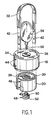
- the apparatus comprises an external body or crown 12 in the form of an inverted cylindrical pot, provided with a bottom wall 14 facing upwards of a cylindrical skirt 16 of vertical axis with thinned peripheral edge 18.
- a heavy body 20 in the form of a cylindrical tank with an outside diameter smaller than the inside diameter of the crown, so that it can move without friction in the latter.
- the heavy body comprises a bottom 22 turned downwards and a cylindrical skirt 24.
- a tubular column 26 coaxial with the skirt 24 stands on the bottom 22. This column is traversed axially right through by a tapping 28.
- the tubular space defined between the skirt 24 and the column 26 receives a flow of ballast material 30, for example lead.
- the device can be transported by means of a handle 32, the ends of which are fixed to two flat rods, 42 which playfully pass through two holes 34, 36, pierced in the bottom 14 of the external body.
- the ends of these rods are fixed, for example by means of screws 38, in axial grooves 40 of the side wall of the heavy body 20.
- the crown has holes 44 on its side wall for the passage of the screws 38.
- the assembly of the handle to the heavy body is therefore done as follows: the heavy body being inside the crown, the latter is rotated about its axis in order to bring the holes 44 and coincide the screw holes 46 of the heavy body.
- the rods 42 which are integral with the handle are then engaged in the slots 34, 36 and their ends are made to slide in the grooves 40.
- the rods can then be secured to the heavy body by passing the screws 38 through the holes 44.
- a pressure piece 48 comprising a threaded rod 50 which screws into the tapping 28 and a flat head 52 of larger diameter.
- the dimensions of the various elements are chosen so that when the heavy body is brought into its high position (FIG. 2), the lower face of the head 52 is exactly in the plane of the lower edge 18 of the crown.
- a comparator 54 of a conventional type which comprises a housing 56 from which protrudes a detection needle 58. This passes through the bottom wall 14 and freely penetrates the tapping 28. This needle can be inserted into the housing 56 against elastic return means not shown and, in this movement, it drives, by means of return means, a reading needle 60 in front of a graduated scale 62.
- the end of the detection needle 58 takes bearing on a fixed reference surface formed by the upper face of a grub screw 64 which is screwed into the thread 28. This screw is positioned at a given distance in the thread 28.
- the apparatus is then placed on the plate 10.
- the crown 12 is posed and exerts on the cardboard a given moderate pressure practically not deforming it, while the head 52 of the pressure piece, under the action of the mass of the movable assembly constituted by the body weighing 20 and the handle 32, sinks into the carton. Said mass therefore descends from the height whose flat head of the pressure piece has penetrated into the carton.
- the reading needle 60 deviates and is placed in front of a scale indicating the difference in thickness of the plate by the relative depression of the heavy body relative to the crown. This position is illustrated in Figure 3.
Abstract
Description
La présente invention concerne un appareil permettant de contrôler l'épaisseur d'une plaque en matière compressible, par exemple en carton ondulé.The present invention relates to an apparatus for controlling the thickness of a plate of compressible material, for example corrugated cardboard.
Il est connu de procéder régulièrement à la mesure de l'épaisseur des plaques de carton sortant d'une onduleuse, afin de vérifier qu'elles ont bien l'épaisseur requise.It is known to regularly measure the thickness of the cardboard sheets leaving a corrugator, in order to verify that they have the required thickness.
Par le brevet n° 2 569 849 on connaît un appareil de ce type qui comprend une plaque fixe sur laquelle un échantillon de carton est posé, une plaque mobile parallèle à la plaque fixe venant écraser l'échantillon contre la plaque fixe sous l'action de charges prédéterminées, et un appareil de lecture destiné à mesurer la profondeur de l'enfoncement de la plaque mobile dans l'échantillon. A cet effet, la plaque fixe est munie d'une aiguille saillante qui traverse l'échantillon de carton. L'appareil de mesure comporte des moyens capables de mesurer la longueur d'aiguille qui dépasse au-dessus de l'échantillon. Les charges appliquées à la plaque mobile sont portées par un système de leviers montés pivotants sur un bâti support.Patent No. 2,569,849 discloses an apparatus of this type which comprises a fixed plate on which a cardboard sample is placed, a movable plate parallel to the fixed plate crushing the sample against the fixed plate under the action. of predetermined loads, and a reading device intended to measure the depth of the depression of the movable plate in the sample. For this purpose, the fixed plate is provided with a protruding needle which passes through the cardboard sample. The measuring apparatus includes means capable of measuring the length of needle which protrudes above the sample. The loads applied to the movable plate are carried by a system of levers pivotally mounted on a support frame.
Un tel appareil est d'une structure encombrante, de mise en oeuvre compliquée, de fiabilité insuffisante, et de plus crée un trou d'endommagement dans les articles contrôlés par la percée de l'aiguille de mesure.Such an apparatus is of a bulky structure, of complicated implementation, of insufficient reliability, and moreover creates a hole of damage in the articles checked by the piercing of the measuring needle.
Le brevet U.S.A. 1 927 821 concerne également un appareil de mesure de l'épaisseur de feuilles en matière plastique qui comporte deux roues tranchantes destinées à couper la feuille sur toute son épaisseur. Il présente donc le grave inconvénient d'endommager la feuille.U.S. Patent 1,927,821 also relates to a device for measuring the thickness of plastic sheets which has two cutting wheels for cutting the sheet over its entire thickness. It therefore has the serious disadvantage of damaging the sheet.
Le modèle d'utilité allemand n° 7 015 142 présente également le même défaut puisqu'il comporte un plongeur se terminant par une pointe qui perce la feuille.The German utility model n ° 7 015 142 also has the same defect since it includes a plunger ending in a point which pierces the leaf.
La présente invention a pour but de remédier à ces inconvénients de la technique antérieure connue en proposant un appareil pour le contrôle de l'épaisseur d'une plaque en matière compressible, par exemple en carton ondulé, qui soit léger afin de pouvoir être déplaçable en n'importe quel point, qui ne nécessite pour son fonctionnement aucun réglage d'un quelconque de ses éléments, qui soit d'une grande résistance mécanique et donc non sujet aux détériorations, et enfin qui n'endommage pas l'échantillon à tester.The object of the present invention is to remedy these drawbacks of the known prior art by proposing an apparatus for controlling the thickness of a plate of compressible material, for example of corrugated cardboard, which is light so that it can be moved at any point, which does not require any adjustment of any of its elements for its operation , which is of great mechanical strength and therefore not subject to deterioration, and finally which does not damage the sample to be tested.
L'appareil selon l'invention se caractérise en ce qu'il comprend :
- un corps extérieur ou couronne d'axe vertical en forme de pot cylindrique retourné, et susceptible de prendre appui sans l'endommager, sur un échantillon de plaque de matière par le bord inférieur de sa paroi cylindrique,
- un corps pesant de forme cylindrique, monté coulissant coaxialement à l'intérieur de la couronne entre une position soulevée où sa face supérieure est en butée contre la couronne et où sa face inférieure se trouve exactement dans le même plan que ledit bord inférieur de la couronne et affleure donc la surface de la plaque de matière, et une position basse où il repose de tout son poids sur ladite plaque et la comprime sans la percer,
- et un comparateur apte à mesurer la course du corps pesant résultant de son enfoncement dans la plaque de matière à partir de sa position haute définie ci-dessus, lorsque l'appareil de contrôle est posé sur la plaque.The apparatus according to the invention is characterized in that it comprises:
an outer body or crown of vertical axis in the form of an inverted cylindrical pot, and capable of bearing without damaging it, on a sample of material plate by the lower edge of its cylindrical wall,
- a heavy body of cylindrical shape, mounted to slide coaxially inside the crown between a raised position where its upper face abuts against the crown and where its lower face is in exactly the same plane as said lower edge of the crown and therefore flush with the surface of the material plate, and a low position where it rests with all its weight on said plate and compresses it without piercing it,
- And a comparator able to measure the stroke of the heavy body resulting from its insertion into the material plate from its high position defined above, when the control device is placed on the plate.
L'appareil selon l'invention peut être porté en bloc à la main au moyen d'une anse située au-dessus de la paroi de fond de la couronne et dont les bras traversent avec jeu des lumières percées dans ladite paroi de fond et sont fixés, de préférence avec des moyens de fixation amovibles, à la paroi latérale du corps pesant.The apparatus according to the invention can be worn as a block by hand by means of a handle situated above the bottom wall of the crown and whose arms playfully pass through holes drilled in said bottom wall and are fixed, preferably with removable fixing means, to the side wall of the heavy body.
Lesdites lumières sont avantageusement en forme d'arc de cercle afin de permettre le pivotement de l'ensemble de l'anse et du corps pesant autour de l'axe de ce dernier et d'asseoir ainsi au mieux le corps pesant sur la plaque de matière sans bouger la couronne.Said openings are advantageously in the form of an arc of a circle in order to allow the pivoting of the assembly of the handle and of the heavy body around the axis of the latter and thus to best sit the heavy body on the plate. material without moving the crown.
Le corps intérieur est rendu pesant par tout moyen de lestage approprié. Par exemple, le corps pesant peut être en forme de cuve cylindrique sur le fond de laquelle se dresse une colonne tubulaire coaxiale, de même hauteur que la paroi latérale du corps pesant, l'espace annulaire compris entre ladite paroi latérale et la colonne étant rempli d'une coulée de matière lourde solidifiée, par exemple du plomb.The inner body is made heavy by any appropriate ballasting means. For example, the heavy body may be in the form of a cylindrical tank on the bottom of which stands a coaxial tubular column, of the same height as the side wall of the heavy body, the annular space between said side wall and the column being filled a flow of solidified heavy material, for example lead.
La colonne tubulaire du corps pesant présente sur toute sa hauteur un taraudage qui le traverse de part en part. Dans l'extrémité inférieure dudit taraudage est vissée une pièce de pression comprenant une tige filetée vissée dans le taraudage et une tête plate dont la face inférieure peut être amenée, par vissage, dans le même plan que le bord inférieur de la couronne.The tubular column of the heavy body has a thread which runs right through it over its entire height. In the lower end of said thread is screwed a pressure piece comprising a threaded rod screwed into the thread and a flat head whose lower face can be brought, by screwing, in the same plane as the lower edge of the crown.
De plus, la surface de ladite tête plate est calculée en fonction de la masse de l'ensemble du corps pesant de manière que sous l'effet de la pression qui en résulte, la tête comprime la plaque de matière sous une pression déterminée.In addition, the surface of said flat head is calculated as a function of the mass of the entire weighing body so that under the effect of the pressure which results therefrom, the head compresses the material plate under a determined pressure.
On notera que le même appareil pourra servir pour contrôler l'épaisseur de plaque de matière de résistances différentes. Il suffit pour cela d'utiliser une vis ayant une tête de diamètre choisi pour qu'elle comprime l'échantillon de matière sous une pression déterminée.Note that the same device can be used to control the thickness of the plate of material of different resistances. For this, it suffices to use a screw having a head of chosen diameter so that it compresses the sample of material under a determined pressure.
Le comparateur est constitué de façon connue en soi par un micromètre, du type comprenant un boîtier d'où fait saillie une aiguille de détection, qui est susceptible d'être enfoncée dans ledit boîtier à l'encontre de moyens élastiques de rappel, ce mouvement entraînant, par l'intermédiaire de moyens de renvoi, le déplacement d'une aiguille de lecture devant une échelle graduée qui indique la course d'enfoncement du corps pesant dans la plaque en matière compressible.The comparator is constituted in a manner known per se by a micrometer, of the type comprising a housing from which protrudes a detection needle, which is capable of being pressed into said housing against elastic return means, this movement causing, by means of deflection, the displacement of a reading needle in front of a graduated scale which indicates the stroke of insertion of the heavy body in the plate of compressible material.
Ledit boîtier est fixé à l'extérieur sur la paroi de fond de la couronne et son aiguille de détection traverse librement ladite paroi de fond, son extrémité faisant saillie à l'intérieur de la colonne tubulaire, et prenant appui sur une surface fixe de référence du corps pesant.Said housing is fixed to the outside on the bottom wall of the crown and its detection needle freely passes through said bottom wall, its end projecting inside the tubular column, and taking support on a fixed reference surface of the heavy body.
Cette surface de référence est constituée par l'extrémité d'une vis sans tête qui est réglée par vissage dans le taraudage de la colonne du corps pesant.This reference surface is formed by the end of a grub screw which is adjusted by screwing in the thread of the column of the heavy body.
Une forme de réalisation de l'appareil de contrôle selon l'invention ainsi que son mode d'utilisation seront décrits à présent à titre d'exemple non limitatif en regard du dessin annexé dans lequel :
- La figure 1 est une vue en perspective éclatée de l'appareil de contrôle de l'épaisseur ;
- La figure 2 est une vue en coupe axiale de l'appareil en position soulevée au-dessus d'une plaque de carton ondulé ; et
- La figure 3 est une vue analogue, l'appareil étant posé sur la plaque de carton ondulé.
- Figure 1 is an exploded perspective view of the thickness control apparatus;
- Figure 2 is an axial sectional view of the apparatus in the raised position above a corrugated board; and
- Figure 3 is a similar view, the apparatus being placed on the corrugated board.
L'invention sera expliquée ci-après à propos de la mesure de l'épaisseur d'une plaque de carton ondulé 10, mais il va de soi qu'elle s'applique à toute plaque en matière quelconque compressible.The invention will be explained below in connection with the measurement of the thickness of a
L'appareil comprend un corps externe ou couronne 12 en forme de pot cylindrique retourné, pourvue d'une paroi de fond 14 tournée vers le haut d'une jupe cylindrique 16 d'axe vertical à bord périphérique aminci 18.The apparatus comprises an external body or
A l'intérieur de la couronne est logé coaxialement un corps pesant 20 en forme de cuve cylindrique de diamètre extérieur inférieur au diamètre intérieur de la couronne, de sorte qu'il peut se déplacer sans frottement dans ce dernier. Le corps pesant comprend un fond 22 tourné vers le bas et une jupe cylindrique 24. Une colonne tubulaire 26 coaxiale à la jupe 24 se dresse sur le fond 22. Cette colonne est traversée axialement de part en part par un taraudage 28.Inside the crown is housed coaxially a
L'espace tubulaire défini entre la jupe 24 et la colonne 26 reçoit une coulée de matière de lestage 30, par exemple de plomb.The tubular space defined between the
L'appareil peut être transporté au moyen d'une anse 32 dont les extrémités sont fixées à deux tiges plates, 42 qui traversent avec jeu deux lumières 34, 36, percées dans le fond 14 du corps externe. Les extrémités de ces tiges sont fixées, par exemple au moyen de vis 38, dans des rainures axiales 40 de la paroi latérale du corps pesant 20. La couronne présente sur sa paroi latérale des trous 44 pour le passage des vis 38.The device can be transported by means of a
L'assemblage de l'anse au corps pesant se fait donc de la façon suivante : le corps pesant se trouvant à l'intérieur de la couronne, on fait tourner cette dernière autour de son axe afin d'amener en coïncidence les trous 44 et les trous des vissages 46 du corps pesant. On engage ensuite les tiges 42 solidaires de l'anse dans les lumières 34, 36 et on fait coulisser leurs extrémités dans les rainures 40. Les tiges peuvent alors être solidarisées du corps pesant en faisant passer les vis 38 à travers les trous 44.The assembly of the handle to the heavy body is therefore done as follows: the heavy body being inside the crown, the latter is rotated about its axis in order to bring the
Lorsqu'on soulève l'appareil en le tenant par l'anse, le corps pesant 20 est en butée contre la face interne de la paroi de fond 14 de la couronne, comme le montre la figure 2.When the apparatus is lifted by holding it by the handle, the
Sur la face inférieure du corps pesant est fixée une pièce de pression 48 comprenant une tige filetée 50 qui se visse dans le taraudage 28 et une tête plate 52 de plus grand diamètre.On the underside of the heavy body is fixed a
Les dimensions des différents éléments sont choisies pour que lorsque le corps pesant est amené dans sa position haute (figure 2), la face inférieure de la tête 52 se trouve exactement dans le plan du bord inférieur 18 de la couronne.The dimensions of the various elements are chosen so that when the heavy body is brought into its high position (FIG. 2), the lower face of the
Sur la paroi de fond 14 est fixé un comparateur 54 d'un type classique qui comprend un boîtier 56 d'où fait saillie une aiguille de détection 58. Celle-ci traverse la paroi de fond 14 et pénètre librement dans le taraudage 28. Cette aiguille peut être enfoncée dans le boîtier 56 à l'encontre de moyens élastiques de rappel non représentés et, dans ce mouvement, elle entraîne, par l'intermédiaire de moyens de renvoi, une aiguille de lecture 60 devant une échelle graduée 62.On the
L'extrémité de l'aiguille de détection 58 prend appui sur une surface fixe de référence constituée par la face supérieure d'une vis sans tête 64 qui est vissée dans le taraudage 28. Cette vis est positionnée à une distance donnée dans le taraudage 28.The end of the
On décrira à présent le mode d'utilisation de l'appareil : on transporte celui-ci, en le tenant par son anse 32, au-dessus de la plaque de carton ondulé 10. Le corps pesant 20 est alors en butée contre la paroi de fond 14 de la couronne. On règle manuellement le comparateur 54 pour amener le zéro de la graduation de lecture 62 devant l'aiguille.The mode of use of the apparatus will now be described: it is transported, holding it by its
On pose ensuite l'appareil sur la plaque 10. La couronne 12 se pose et exerce sur le carton une pression modérée donnée ne le déformant pratiquement pas, tandis que la tête 52 de la pièce de pression, sous l'action de la masse de l'équipage mobile constitué par le corps pesant 20 et l'anse 32, s'enfonce dans le carton. Ladite masse descend donc de la hauteur dont la tête plate de la pièce de pression a pénétré dans le carton. L'aiguille de lecture 60 dévie et se place devant une graduation indiquant la différence d'épaisseur de la plaque par l'enfoncement relatif du corps pesant par rapport à la couronne. Cette position est illustrée par la figure 3.The apparatus is then placed on the
Pour obtenir différentes pressions déterminées du corps pesant sur des plaques, on doit adapter des pièces de pression à tête plate de diamètres donnés.To obtain different determined pressures of the body weighing on plates, flat head pressure pieces of given diameters must be adapted.
Claims (7)
- un corps extérieur ou couronne (12) d'axe vertical en forme de pot cylindrique retourné, et susceptible de prendre appui, sans l'endommager, sur un échantillon de plaque de matière (10) par le bord inférieur (18) de sa paroi cylindrique (16),
- un corps pesant (20) de forme cylindrique, monté coulissant coaxialement à l'intérieur de la couronne entre une position soulevée où sa face supérieure est en butée contre la couronne et où sa face inférieure se trouve exactement dans le même plan que ledit bord inférieur (18) de la couronne et affleure donc la surface de la plaque de matière (10), et une position basse où il repose de tout son poids sur ladite plaque et la comprime sans la percer,
- et un comparateur (54) apte à mesurer la course du corps pesant résultant de son enfoncement dans la plaque de matière à partir de sa position haute définie ci-dessus, lorsque l'appareil de contrôle est posé sur la plaque.1. Apparatus for controlling the thickness of a plate of compressible material, in particular corrugated cardboard, characterized in that it comprises:
- An outer body or crown (12) of vertical axis in the form of an inverted cylindrical pot, and capable of bearing, without damaging it, on a sample of material plate (10) by the lower edge (18) of its cylindrical wall (16),
- a heavy body (20) of cylindrical shape, mounted to slide coaxially inside the crown between a raised position where its upper face is in abutment against the crown and where its lower face is in exactly the same plane as said edge lower (18) of the crown and is therefore flush with the surface of the material plate (10), and a low position where it rests with its full weight on said plate and compresses it without piercing it,
- And a comparator (54) able to measure the stroke of the heavy body resulting from its insertion into the material plate from its high position defined above, when the control device is placed on the plate.
Applications Claiming Priority (2)
| Application Number | Priority Date | Filing Date | Title |
|---|---|---|---|
| FR8910365A FR2650663A1 (en) | 1989-08-01 | 1989-08-01 | APPARATUS FOR CONTROLLING THE THICKNESS OF A PLATE IN COMPRESSIBLE MATERIAL, ESPECIALLY IN CORRUGATED CARDBOARD |
| FR8910365 | 1989-08-01 |
Publications (2)
| Publication Number | Publication Date |
|---|---|
| EP0411994A1 true EP0411994A1 (en) | 1991-02-06 |
| EP0411994B1 EP0411994B1 (en) | 1992-10-21 |
Family
ID=9384364
Family Applications (1)
| Application Number | Title | Priority Date | Filing Date |
|---|---|---|---|
| EP90402162A Expired - Lifetime EP0411994B1 (en) | 1989-08-01 | 1990-07-26 | Apparatus for controlling the thickness of a compressible sheet like a corrugated cardboard |
Country Status (7)
| Country | Link |
|---|---|
| EP (1) | EP0411994B1 (en) |
| AT (1) | ATE81718T1 (en) |
| DE (1) | DE69000400T2 (en) |
| DK (1) | DK0411994T3 (en) |
| ES (1) | ES2036099T3 (en) |
| FR (1) | FR2650663A1 (en) |
| GR (1) | GR3006044T3 (en) |
Cited By (1)
| Publication number | Priority date | Publication date | Assignee | Title |
|---|---|---|---|---|
| CN101608890A (en) * | 2009-07-21 | 2009-12-23 | 河南省西峡汽车水泵股份有限公司 | A kind of measuring method of the height of water pump water seal and specific purpose tool |
Citations (4)
| Publication number | Priority date | Publication date | Assignee | Title |
|---|---|---|---|---|
| US1927821A (en) * | 1930-01-29 | 1933-09-26 | Morgan & Wright | Measuring device |
| DE1623251B1 (en) * | 1967-11-17 | 1971-03-11 | Arthur Meissner Kg | Measuring device for determining thicknesses and the physical quantities derived from them at a certain measuring pressure for compressible, preferably flat materials |
| FR2569849A1 (en) * | 1984-09-06 | 1986-03-07 | Promption Expansion Carton | Device for measuring the thickness under different loads of a material in sheet form, such as corrugated cardboard |
| DE3544610A1 (en) * | 1985-12-17 | 1987-06-19 | Max Planck Gesellschaft | Measuring device for a stack of sheets |
Family Cites Families (1)
| Publication number | Priority date | Publication date | Assignee | Title |
|---|---|---|---|---|
| DE7015142U (en) * | 1970-04-23 | 1970-11-19 | Hajtomu Es Felvonogyar | LAYER THICKNESS MEASURING DEVICE. |
-
1989
- 1989-08-01 FR FR8910365A patent/FR2650663A1/en active Pending
-
1990
- 1990-07-26 AT AT90402162T patent/ATE81718T1/en not_active IP Right Cessation
- 1990-07-26 ES ES199090402162T patent/ES2036099T3/en not_active Expired - Lifetime
- 1990-07-26 DK DK90402162.3T patent/DK0411994T3/en active
- 1990-07-26 EP EP90402162A patent/EP0411994B1/en not_active Expired - Lifetime
- 1990-07-26 DE DE9090402162T patent/DE69000400T2/en not_active Expired - Fee Related
-
1992
- 1992-10-22 GR GR920402181T patent/GR3006044T3/el unknown
Patent Citations (4)
| Publication number | Priority date | Publication date | Assignee | Title |
|---|---|---|---|---|
| US1927821A (en) * | 1930-01-29 | 1933-09-26 | Morgan & Wright | Measuring device |
| DE1623251B1 (en) * | 1967-11-17 | 1971-03-11 | Arthur Meissner Kg | Measuring device for determining thicknesses and the physical quantities derived from them at a certain measuring pressure for compressible, preferably flat materials |
| FR2569849A1 (en) * | 1984-09-06 | 1986-03-07 | Promption Expansion Carton | Device for measuring the thickness under different loads of a material in sheet form, such as corrugated cardboard |
| DE3544610A1 (en) * | 1985-12-17 | 1987-06-19 | Max Planck Gesellschaft | Measuring device for a stack of sheets |
Cited By (1)
| Publication number | Priority date | Publication date | Assignee | Title |
|---|---|---|---|---|
| CN101608890A (en) * | 2009-07-21 | 2009-12-23 | 河南省西峡汽车水泵股份有限公司 | A kind of measuring method of the height of water pump water seal and specific purpose tool |
Also Published As
| Publication number | Publication date |
|---|---|
| DE69000400T2 (en) | 1993-03-25 |
| ATE81718T1 (en) | 1992-11-15 |
| GR3006044T3 (en) | 1993-06-21 |
| DK0411994T3 (en) | 1992-11-16 |
| DE69000400D1 (en) | 1992-11-26 |
| EP0411994B1 (en) | 1992-10-21 |
| FR2650663A1 (en) | 1991-02-08 |
| ES2036099T3 (en) | 1993-05-01 |
Similar Documents
| Publication | Publication Date | Title |
|---|---|---|
| FR2477442A1 (en) | ANGLE MEASURING DEVICE FOR PRESSES TO BE FOLDED | |
| EP0634624B1 (en) | Device for measuring a clamping force applied by a movable rod of a length measuring device | |
| CH459586A (en) | Device for marking, checking or measuring places on flat surfaces | |
| EP0014120A1 (en) | Pipette with positive displacement | |
| EP0236371B1 (en) | Digital display micrometer | |
| FR2473124A1 (en) | DEVICE FOR COLLECTING AND DISPENSING DIGITAL ADJUSTABLE VOLUMES OF LIQUIDS | |
| EP0411994B1 (en) | Apparatus for controlling the thickness of a compressible sheet like a corrugated cardboard | |
| FR2737562A1 (en) | FIXED RECONFIGURABLE SUPPORT APPARATUS, ESPECIALLY FOR MEASURING MACHINES, AND CONFIGURATION METHOD THEREFOR | |
| FR2459462A1 (en) | Diaphragm dynamometer for measurement of applied force - has axial guide assembly with capacitive sensor on load shaft | |
| EP0508914A1 (en) | Apparatus for measuring the elongation of sample strips | |
| FR2473169A1 (en) | PROBE DEVICE FOR MEASURING SURFACE ROUGHNESS | |
| CH643145A5 (en) | DEVICE FOR COLLECTING A PREDETERMINED AND ADJUSTABLE VOLUME OF LIQUID IN A CONTAINER. | |
| CH659024A5 (en) | Probe for measurement devices linear sizes of comparative. | |
| EP0260583A1 (en) | Feeler for measuring dimensions | |
| WO1995024463A1 (en) | Applicator device for a flat microorganism collecting element such as a petri dish | |
| CH413398A (en) | Device for measuring the thickness of an object or a coating | |
| FR2570823A1 (en) | APPARATUS FOR MEASURING SURFACE CONTAMINATION BY THE FROTTIS METHOD | |
| FR2469697A1 (en) | Optical measurement of printing cylinder dia. - uses electronic probe and micrometer screw to sense position of laser source | |
| FR2534683A1 (en) | Extensometer, especially for hot extensometry. | |
| CH703905A1 (en) | Precision rod for use on gripping member to form precision gauge for verifying size of hole during manufacturing of piece, has free end including cylindrical region whose diameter corresponds to work diameter and conical introduction region | |
| FR2872894A3 (en) | Measuring tape, has case with tape measure, and stop plate at free end or head of measure graduated on concave and convex sides, with same graduation, with coinciding starting/zero points, and zero line of graduation coincides with head | |
| FR2543029A1 (en) | Method and device for automatic marking of necked metallic cylinders | |
| FR2921671A1 (en) | DEVICE FOR ASSISTING A THREADING TOOL | |
| FR2621113A1 (en) | Measurement instrument, in particular for games of bowls (boules) | |
| WO2005038392A2 (en) | Optical device for determining at least one dimensional characteristic of a drop of liquid |
Legal Events
| Date | Code | Title | Description |
|---|---|---|---|
| PUAI | Public reference made under article 153(3) epc to a published international application that has entered the european phase |
Free format text: ORIGINAL CODE: 0009012 |
|
| AK | Designated contracting states |
Kind code of ref document: A1 Designated state(s): AT BE CH DE DK ES FR GB GR IT LI LU NL SE |
|
| 17P | Request for examination filed |
Effective date: 19910327 |
|
| 17Q | First examination report despatched |
Effective date: 19910927 |
|
| GRAA | (expected) grant |
Free format text: ORIGINAL CODE: 0009210 |
|
| AK | Designated contracting states |
Kind code of ref document: B1 Designated state(s): AT BE CH DE DK ES FR GB GR IT LI LU NL SE |
|
| REF | Corresponds to: |
Ref document number: 81718 Country of ref document: AT Date of ref document: 19921115 Kind code of ref document: T |
|
| REG | Reference to a national code |
Ref country code: DK Ref legal event code: T3 |
|
| REF | Corresponds to: |
Ref document number: 69000400 Country of ref document: DE Date of ref document: 19921126 |
|
| GBT | Gb: translation of ep patent filed (gb section 77(6)(a)/1977) | ||
| ITF | It: translation for a ep patent filed |
Owner name: STUDIO TORTA SOCIETA' SEMPLICE |
|
| REG | Reference to a national code |
Ref country code: GR Ref legal event code: FG4A Free format text: 3006044 |
|
| REG | Reference to a national code |
Ref country code: ES Ref legal event code: FG2A Ref document number: 2036099 Country of ref document: ES Kind code of ref document: T3 |
|
| PLBE | No opposition filed within time limit |
Free format text: ORIGINAL CODE: 0009261 |
|
| STAA | Information on the status of an ep patent application or granted ep patent |
Free format text: STATUS: NO OPPOSITION FILED WITHIN TIME LIMIT |
|
| 26N | No opposition filed | ||
| PGFP | Annual fee paid to national office [announced via postgrant information from national office to epo] |
Ref country code: GB Payment date: 19940726 Year of fee payment: 5 Ref country code: FR Payment date: 19940726 Year of fee payment: 5 |
|
| PGFP | Annual fee paid to national office [announced via postgrant information from national office to epo] |
Ref country code: GR Payment date: 19940727 Year of fee payment: 5 |
|
| PGFP | Annual fee paid to national office [announced via postgrant information from national office to epo] |
Ref country code: DK Payment date: 19940728 Year of fee payment: 5 Ref country code: DE Payment date: 19940728 Year of fee payment: 5 |
|
| PGFP | Annual fee paid to national office [announced via postgrant information from national office to epo] |
Ref country code: ES Payment date: 19940729 Year of fee payment: 5 Ref country code: AT Payment date: 19940729 Year of fee payment: 5 |
|
| PGFP | Annual fee paid to national office [announced via postgrant information from national office to epo] |
Ref country code: SE Payment date: 19940731 Year of fee payment: 5 Ref country code: NL Payment date: 19940731 Year of fee payment: 5 Ref country code: LU Payment date: 19940731 Year of fee payment: 5 |
|
| PGFP | Annual fee paid to national office [announced via postgrant information from national office to epo] |
Ref country code: BE Payment date: 19940810 Year of fee payment: 5 |
|
| EPTA | Lu: last paid annual fee | ||
| PGFP | Annual fee paid to national office [announced via postgrant information from national office to epo] |
Ref country code: CH Payment date: 19941011 Year of fee payment: 5 |
|
| EAL | Se: european patent in force in sweden |
Ref document number: 90402162.3 |
|
| PG25 | Lapsed in a contracting state [announced via postgrant information from national office to epo] |
Ref country code: LU Free format text: LAPSE BECAUSE OF NON-PAYMENT OF DUE FEES Effective date: 19950726 Ref country code: GB Effective date: 19950726 Ref country code: DK Effective date: 19950726 Ref country code: AT Effective date: 19950726 |
|
| REG | Reference to a national code |
Ref country code: DK Ref legal event code: EBP |
|
| PG25 | Lapsed in a contracting state [announced via postgrant information from national office to epo] |
Ref country code: SE Effective date: 19950727 Ref country code: ES Free format text: LAPSE BECAUSE OF THE APPLICANT RENOUNCES Effective date: 19950727 |
|
| PG25 | Lapsed in a contracting state [announced via postgrant information from national office to epo] |
Ref country code: LI Effective date: 19950731 Ref country code: CH Effective date: 19950731 Ref country code: BE Effective date: 19950731 |
|
| BERE | Be: lapsed |
Owner name: SOC. POUR LA PROMOTION ET L'EXPANSION DU CARTON ON Effective date: 19950731 |
|
| PG25 | Lapsed in a contracting state [announced via postgrant information from national office to epo] |
Ref country code: GR Free format text: THE PATENT HAS BEEN ANNULLED BY A DECISION OF A NATIONAL AUTHORITY Effective date: 19960131 |
|
| PG25 | Lapsed in a contracting state [announced via postgrant information from national office to epo] |
Ref country code: NL Effective date: 19960201 |
|
| REG | Reference to a national code |
Ref country code: CH Ref legal event code: PL |
|
| GBPC | Gb: european patent ceased through non-payment of renewal fee |
Effective date: 19950726 |
|
| REG | Reference to a national code |
Ref country code: GR Ref legal event code: MM2A Free format text: 3006044 |
|
| NLV4 | Nl: lapsed or anulled due to non-payment of the annual fee |
Effective date: 19960201 |
|
| PG25 | Lapsed in a contracting state [announced via postgrant information from national office to epo] |
Ref country code: DE Effective date: 19960402 |
|
| EUG | Se: european patent has lapsed |
Ref document number: 90402162.3 |
|
| PG25 | Lapsed in a contracting state [announced via postgrant information from national office to epo] |
Ref country code: FR Effective date: 19960430 |
|
| REG | Reference to a national code |
Ref country code: FR Ref legal event code: ST |
|
| REG | Reference to a national code |
Ref country code: FR Ref legal event code: ST |
|
| REG | Reference to a national code |
Ref country code: FR Ref legal event code: ST |
|
| REG | Reference to a national code |
Ref country code: ES Ref legal event code: FD2A Effective date: 19991007 |
|
| PG25 | Lapsed in a contracting state [announced via postgrant information from national office to epo] |
Ref country code: IT Free format text: LAPSE BECAUSE OF NON-PAYMENT OF DUE FEES;WARNING: LAPSES OF ITALIAN PATENTS WITH EFFECTIVE DATE BEFORE 2007 MAY HAVE OCCURRED AT ANY TIME BEFORE 2007. THE CORRECT EFFECTIVE DATE MAY BE DIFFERENT FROM THE ONE RECORDED. Effective date: 20050726 |