EP0411329B1 - A continuous semi-liquid casting process and a furnace for performing the process - Google Patents
A continuous semi-liquid casting process and a furnace for performing the process Download PDFInfo
- Publication number
- EP0411329B1 EP0411329B1 EP90112546A EP90112546A EP0411329B1 EP 0411329 B1 EP0411329 B1 EP 0411329B1 EP 90112546 A EP90112546 A EP 90112546A EP 90112546 A EP90112546 A EP 90112546A EP 0411329 B1 EP0411329 B1 EP 0411329B1
- Authority
- EP
- European Patent Office
- Prior art keywords
- furnace
- alloy
- interior
- fluid
- casting
- Prior art date
- Legal status (The legal status is an assumption and is not a legal conclusion. Google has not performed a legal analysis and makes no representation as to the accuracy of the status listed.)
- Expired - Lifetime
Links
Images

Classifications
-
- B—PERFORMING OPERATIONS; TRANSPORTING
- B22—CASTING; POWDER METALLURGY
- B22D—CASTING OF METALS; CASTING OF OTHER SUBSTANCES BY THE SAME PROCESSES OR DEVICES
- B22D39/00—Equipment for supplying molten metal in rations
- B22D39/06—Equipment for supplying molten metal in rations having means for controlling the amount of molten metal by controlling the pressure above the molten metal
-
- C—CHEMISTRY; METALLURGY
- C22—METALLURGY; FERROUS OR NON-FERROUS ALLOYS; TREATMENT OF ALLOYS OR NON-FERROUS METALS
- C22C—ALLOYS
- C22C1/00—Making non-ferrous alloys
- C22C1/12—Making non-ferrous alloys by processing in a semi-solid state, e.g. holding the alloy in the solid-liquid phase
Definitions
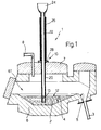
- the reference 1 indicates a furnace for casting a metal alloy 2 in a semi-liquid state, in particular for casting a light alloy, by passing this through a static mixer 3 of known type, illustrated only schematically as a cylindrical tube;
- the furnace 1 which is internally clad with a known refractory lining, not illustrated for simplicity, comprises a body 6 in the bottom of which are formed, in adjacent positions, a refractory monolithic lining material 4 and a casting aperture 5 connected, with a fluid-tight seal, to a static mixer 3, which is fixed to the body 6 in question immediately beneath the casting aperture 5; above the refractory monolithic lining material 4 and the casting aperture 5, which defines a lower portion of the furnace 1, the body 6 delimits a chamber 61 defining the upper portion of the furnace 1 and housing, in a known manner not illustrated for simplicity, suitable heating means, for example electrical resistances.
Description
- The present invention relates to a process for casting a metal alloy continuously in a semi-liquid state, in particular for casting a light alloy usable for casting components of the fuel supply system of a heat engine. The invention further relates to a furnace for performing this process.
- A static mixer is known from Italian Patent No 1,119,287 filed 20 June 1979 and entitled: "Process for the preparation of a mixture comprising a solid phase and a liquid phase of a metal alloy and device for performing this process", the contents of which are incorporated herein as far as necessary by reference, the static mixer being of the type formed by a cylindrical casting channel within which are disposed in succession a series of helically wound blades or paddles, by means of which it is possible to cast a metal alloy by obtaining partial solidification, during casting, within the passage of the static mixer, with simultaneous mixing of the solid phase, upon formation, with the remaining liquid phase in such a way as to form at the output from the static mixer a solid/liquid mixture in which the solid phase separating out from the liquid alloy is uniformly dispersed in suspension within the liquid alloy itself. The mixture thus obtained is stable for a sufficiently long period of time to permit collection in a ladle and subsequent casting in moulds to obtain castings having particular and valuable microstructural characteristics.
- To be able to obtain these characteristics, however, the solid/liquid mixture must be obtained in stationary fluid dynamics conditions and it is necessary to be able to control with precision and speed the physical and dynamic parameters of the casting (temperature gradient of cooling of the alloy, speed of transit through the static mixer, etc); this necessity involves, on the one hand, having to effect casting by the use of pressurised furnaces so that the casting cannot be performed continuously, but only as a batch process; and on the other hand it involves the necessity of rejecting not inconsiderable quantities of alloy and, above all, of having to dismantle and clean the static mixer in the interval between one casting and the next; bearing in mind that the furnaces cannot, for practical reasons, have a very high capacity (for example greater than 1000 Kg) this latter disadvantage involves high maintenance costs and, finally, a high cost per unit of cast alloy and a low overall productivity of the system.
- The object of the invention is that of providing a semi-liquid casting process which makes use of the known static mixer described above but which can however be performed continuously. It is a further object of the invention to provide a furnace which can be coupled with a static mixer to perform this semi-liquid casting process continuously.
- The said objects are achieved by the invention in that it relates to a continuous semi-liquid casting process in which a metal alloy in the liquid state is brought into conditions such as to produce separation of a solid phase within the body of the liquid and in which the alloy is moreover made to pass through a static mixer adapted uniformly to mix the solid phase, upon formation, with the liquid alloy in such a way as to obtain at the output from the mixer a temporarily stable suspension; characterised by the fact that it comprises the following stages:
- introducing the molten alloy into a furnace through a barometric column surmounting the said furnace and dipping into the interior thereof, the interior of the said furnace being maintained closed with a fluid-tight seal and connected hydraulically to the said static mixer; and
- supplying the alloy continuously to the said static mixer by pressurising the interior of the furnace to a pressure value such as to cause the said alloy to flow through the said static mixer in stationary laminar conditions.
- The present invention further relates to a furnace for the continuous semi-liquid casting of a metal alloy by making it pass through a static mixer connected in a fluid-tight manner to a casting aperture of the said furnace, characterised by the fact that the said furnace is sealed in a fluid-tight manner and has a monolithic refractory lining adapted to contain a fluid bath of the said alloy, the said monolithic refractory lining being formed alongside the said casting aperture, means for introducing a pressurised gas into the interior of the furnace, above the said monolithic refractory lining, and a barometric column of predetermined height surmounting the said furnace and dipping into the interior of the liquid bath.
- For a better understanding of the invention a non-limitative description of an embodiment thereof is now given with reference to the attached drawings, in which:
- Figure 1 illustrates a side view in section of a furnace formed according to the invention; and
- Figure 2 schematically illustrates the casting process which can be performed with the furnace of Figure 1.
- With reference to Figures 1 and 2 the reference 1 indicates a furnace for casting a
metal alloy 2 in a semi-liquid state, in particular for casting a light alloy, by passing this through a static mixer 3 of known type, illustrated only schematically as a cylindrical tube; the furnace 1, which is internally clad with a known refractory lining, not illustrated for simplicity, comprises abody 6 in the bottom of which are formed, in adjacent positions, a refractorymonolithic lining material 4 and acasting aperture 5 connected, with a fluid-tight seal, to a static mixer 3, which is fixed to thebody 6 in question immediately beneath thecasting aperture 5; above the refractorymonolithic lining material 4 and thecasting aperture 5, which defines a lower portion of the furnace 1, thebody 6 delimits achamber 61 defining the upper portion of the furnace 1 and housing, in a known manner not illustrated for simplicity, suitable heating means, for example electrical resistances. Thechamber 61 is closed in a fluid-tight manner by acover 7 traversed by atube 8 and, according to the invention, by abarometric column 10 of predetermined height surmounting the furnace 1 and dipping into the interior of the monolithicrefractory lining 4; this latter is adapted to contain, in use, afluid bath 12 of themetal alloy 2 of a height such as to ensure the immersion within it of alower end 13 of thebarometric column 10; the furnace 1 is of the rocking type and is therefore adapted to be inclined in use, during the casting stage, by a predetermined angle such as to cause displacement of thefluid bath 12 ofalloy 2, by gravity, partially out from the monolithicrefractory lining 4 to cover and fill thecasting aperture 5, in such a way as to permit thefluid alloy 2 to flow out from the furnace 1 itself, by passing through thecasting aperture 5 and, from there, through the static mixer 3 connected fixedly to it; thebarometric column 10 is disposed in a position such as to remain always immersed, even in this inclined configuration of the furnace 1, in thefluid bath 12 and, therefore, once inclined, the furnace 1, with the refractory monolithic lining filled withfluid alloy 2 is sealed in a fluid-tight manner from the external environment, communicating with the outside only through thetube 8; this is normally connected in a known manner not illustrated for simplicity with a source of pressurised, preferably inert gases, such as argon or nitrogen, in such a way that the interior of the furnace 1 can be pressurised to any predetermined pressure value by introducing a flow of the said pressurised gas into its interior through thetube 8. - In accordance with the invention the
barometric column 10 comprises afirst tube 20 made of graphite and disposed within the furnace 1, fixed so as to pass through thecover 7 and traversing thechamber 61 to terminate within the interior of the monolithicrefractory lining 4 close to the bottom wall of this, and asecond tube 22 surmounting thecover 7 outside the furnace 1 and provided with a funnel shapedupper end 24; thissecond tube 22 is provided externally with heating means defined, in the specific example, by anelectrical resistance 26 wound helically around it, and is connected at its end, in a fluid-tight manner, to thefirst tube 20 by means of a flangedjoint 28 disposed in correspondence with thecover 7. In this way thebarometric column 10 is able to contain thealloy 2 in the fluid state within its interior. - According to the process of the invention, the furnace 1 is charged with a predetermined quantity of
fluid alloy 2 equal to the capacity of the furnace (for example 500 Kg) in a conventional manner and, then, it is closed and assumes the conditions illustrated in Figure 1; the furnace 1 is then inclined bringing it into the position of Figure 2, in such a way as to cover thecasting aperture 5 with thefluid bath 12 and at least partially to fill the static mixer 3; in this condition casting has not yet started in that the furnace 1 is dimensioned and disposed in such a way that the head offluid alloy 2 which is created above the mixer 3 is negligible and insufficient to overcome, on its own, the pressure drop which thealloy 2 experiences in the partial solidification stage in passage through the mixer 3. This head offluid alloy 2 has in fact only the purpose of putting thebarometric column 10, which is immersed in a fluid-tight manner in thebath 12, into hydraulic, sealed, communication with the static mixer 3, which is covered and at least partially filled by thefluid bath 12. Subsequently the interior of the furnace 1 is pressurised by the introduction into an upper portion thereof not occupied by thefluid bath 12, in the specific example thechamber 61, by a flow ofinert gas 30, indicated by the arrows (Figure 2); this flow of gas brings the interior of the furnace 1 up to a pressure P greater than the value of the pressure drop associated with the passage offluid alloy 2 through the mixer 3 and causes casting to commence: thealloy 2 flows from theaperture 5 and passes through the mixer 3; according to the invention, during this phase, thealloy 2 is carried (for example by suitably adjusting its rate of flow by adjustment of the pressure P, regulating its temperature as it leaves the furnace 1 by regulating the said heating means in thechamber 61, and regulating its exit temperature from the mixer 3, along which thealloy 2 experiences a cooling) in conditions such as to produce the segregation within the body of the liquid alloy of a solid phase (not illustrated for simplicity); moreover, the passage of thefluid alloy 2 through the static mixer 3 causes, as described in Italian Patent No 1,119,287 cited above, a uniform mixing of the solid phase upon formation with theliquid alloy 2 in such a way as to obtain at the output from the mixer 3 a temporarily stable suspension, or rather a suspension which is stable for a sufficient time for its use for the production of castings of the desired shape and dimensions. As described in the Patent cited above, the suspension at the output from the mixer 3 is collected for use, for example by suitable ladles not illustrated, only when the fluid-dynamic conditions of thealloy 2 along the mixer 3 are stationary, that is as soon as the initial casting transients have terminated. - According to the invention, for the purpose of indefinitely extending the casting once the stationary conditions have been reached, the rate of flow of
alloy 2 which leaves the furnace 1 through the mixer 3 is balanced by an equal flow of newliquid alloy 2, which is introduced to the interior of the pressurised furnace 1, without reducing the pressurisation thereof, or rather by maintaining the interior of the furnace 1 sealed, through thebarometric column 10; for example, theliquid alloy 2 is introduced in a discrete manner by pouring a predetermined quantity of it at intervals from aladle 40 into thefunnel 24 in such a way as to form and maintain within the barometric column 10 ahead 41 of molten metal alloy of height such as to overcome the pressure P within the interior of the furnace 1. Thisfluid head 41 forms partially, thanks to the presence of thebarometric column 10 and its immersion in thefluid bath 12 upon pressurisation of the furnace 1 by the flow ofinert gas 61; the pressurisation P, which acts on the surface of thefluid bath 12, in fact urges into thebarometric column 10, according to the well known laws of fluid statics, a part of thefluid alloy 2 forming thebath 12 until it forms a fluid head of height such as to balance the pressure P; the introduction ofnew alloy 2 through thefunnel 24 causes an increase in the height of the fluid column present in thebarometric column 10, with the formation of thehead 41 which has a height such as to permit a part of the alloy contained in thecolumn 10 to descend into the interior of the furnace 1 in such a way as to maintain substantially constant the quantity ofalloy 2 which forms thefluid bath 12. Since this latter presents a very much greater surface than the section of thecolumn 10, furthermore, this introduction ofnew fluid alloy 2 takes place without altering the stationary conditions of efflux of thealloy 2 through thecasting aperture 5 in that upon writing the Bernoulli equation for thealloy 2 at the base of thecolumn 10 it is easy to understand that the energy velocity component at this point is zero. For the purpose of compensating the dissipation of heat which can take place in thecolumn 10 and thus permit thealloy 2 remaining in it to stay fluid even for relatively long periods of time the part of thecolumn 10 which is outside the furnace 1, that is thetube 22, is heated from the outside by theresistance 26 during the whole of the casting operation; the part of thecolumn 20 within the furnace, that is thetube 20, does not need suitable heating since it is heated by radiation from the heating means within the furnace 1. - Finally, according to the process of the invention, the value of the pressure P is chosen in such a way as to make the
alloy 2 flow through the static mixer 3 in rigorously laminar conditions so that the mixer 3 can operate correctly. - From what has been described the advantages connected with the invention are evident; thanks to a furnace of very simple structure, which is easy to operate and control, and of economic construction, the casting operation which, according to the state of the art was only possible in a discontinuous manner, can be made continuous entirely without loss of the particularly beneficial microstructural characteristics of the material subjected to treatment through the mixer 3. The possibility of performing continuous casting, which can continue for tens of hours, moreover, makes it possible to reduce to the minimum or even to eliminate entirely the necessity for maintenance of the mixer 3; bearing in mind that this is in any case subject to an inevitable wear so that it must be replaced after a certain number of castings, it is possible to design static mixers 3 having dimensions such as to offer a durability equal to that of an individual continuous caster; the process of the invention therefore makes it possible to utilise "disposable" mixers thus eliminating any necessity for maintenance of the casting installation save for the ordinary maintenance of the refractory lining of the furnace 1.
Claims (7)
- A process for continuous casting in the semi-liquid state, in which a metal alloy (2) in a liquid state is brought into conditions such as to produce the segregation of a solid phase within the body of the liquid alloy and in which the alloy is further made to pass through a static mixer (3) adapted to mix the solid phase uniformly upon formation with the liquid alloy in such a way as to obtain a temporarily stable suspension at the output from the mixer (3); characterised by the fact that it includes the following stages:- introducing the molten alloy (2) into a furnace (1) through a barometric column (10) surmounting the said furnace (1) and dipping into the interior thereof, the interior of the said furnace being maintained closed in a fluid-tight manner and connected hydraulically to the said static mixer (3); and- supplying the alloy (2) continuously to the said static mixer (3) by pressurising the interior of the furnace (1) to a pressure value such as to make the said alloy flow through the static mixer (3) in stationary laminar conditions.
- A process according to Claim 1, characterised by the fact that the said alloy (2) is introduced into the furnace (1) in a discrete manner by pouring a predetermined quantity contained in a ladle (40) into the said barometric column (10) in such a way as to form within the interior of this latter a head (41) of molten metal alloy of height such as to overcome the predetermined pressure within the interior of the furnace (1), the said barometric column (10) being heated externally at least over its section disposed outside the said furnace.
- A process according to Claim 1 or Claim 2, characterised by the fact that the said phase of continuously supplying the said mixer (3) is effected by inclining the said furnace (1) in such a way as to put the said barometric column (10) and the said static mixer (3) in hydraulic communication in a fluid-tight sealed manner through a fluid bath (12) formed by the said alloy (2) and contained within a lower portion of the said furnace, and pressurising the interior of the said furnace by introducing a flow of inert gas into an upper portion (61) thereof not occupied by the said bath.
- A furnace for semi-liquid casting a metal alloy in a continuous manner by making the same pass through a static mixer (3) connected in a fluid-tight sealed manner to a casting aperture (5) of the said furnace (1), characterised by the fact that the said furnace (1) is sealed and includes a refractory monolithic lining (4) adapted to contain a fluid bath (12) of the said alloy, the said refractory monolithic lining (4) being formed adjacent the said casting aperture (5), means (8) for introducing a pressurised gas to the interior of the furnace above the said refractory monolithic lining (4), and a barometric column (10) of predetermined height surmounting the said furnace (1) and dipping into the interior of the fluid bath (12).
- A furnace according to Claim 4, characterised by the fact that it is adapted to be inclined at an angle such as to produce by gravity displacement of the said fluid bath (12) of alloy partially out from the refractory monolithic lining (4) to cover the said casting aperture (5), the said barometric column (10) being disposed in a position such as to remain still immersed in the said fluid bath (12).
- A furnace according to Claim 4 or Claim 5, characterised by the fact that the said means for introducing pressurised gas comprise at least one tube (8) formed so as to pass through a cover (7) of the said furnace (1).
- A furnace according to Claim 6, characterised by the fact that the said barometric column (10) includes a first tube (20) made of graphite disposed within the interior of the said furnace, fixed in position passing through the said cover (7), and a second tube (22) surmounting the said cover (7) outside the furnace; the said second tube (22) being provided with heating means (26) and being connected in a fluid-tight sealed manner to the first tube (20) by means of a flanged joint (28).
Applications Claiming Priority (2)
| Application Number | Priority Date | Filing Date | Title |
|---|---|---|---|
| IT6762789 | 1989-07-25 | ||
| IT8967627A IT1233232B (en) | 1989-07-25 | 1989-07-25 | CONTINUOUS SEMIQUID CASTING PROCEDURE AND OVEN FOR ITS REALIZATION |
Publications (2)
| Publication Number | Publication Date |
|---|---|
| EP0411329A1 EP0411329A1 (en) | 1991-02-06 |
| EP0411329B1 true EP0411329B1 (en) | 1994-06-01 |
Family
ID=11304015
Family Applications (1)
| Application Number | Title | Priority Date | Filing Date |
|---|---|---|---|
| EP90112546A Expired - Lifetime EP0411329B1 (en) | 1989-07-25 | 1990-07-02 | A continuous semi-liquid casting process and a furnace for performing the process |
Country Status (7)
| Country | Link |
|---|---|
| US (1) | US5119977A (en) |
| EP (1) | EP0411329B1 (en) |
| BR (1) | BR9003601A (en) |
| DE (1) | DE69009333T2 (en) |
| ES (1) | ES2057286T3 (en) |
| IT (1) | IT1233232B (en) |
| RU (1) | RU1838029C (en) |
Families Citing this family (9)
| Publication number | Priority date | Publication date | Assignee | Title |
|---|---|---|---|---|
| IT1257114B (en) * | 1992-09-29 | 1996-01-05 | Weber Srl | PROCEDURE FOR OBTAINING REOCOLATED SOLID WOODS, IN PARTICULAR SUITABLE FOR USE FOR THE PRODUCTION OF HIGH MECHANICAL PERFORMANCE DIE CASTINGS. |
| IT1260684B (en) * | 1993-09-29 | 1996-04-22 | Weber Srl | METHOD AND PLANT FOR THE DIE-CASTING OF SEMI-LIQUID COMPONENTS WITH HIGH MECHANICAL PERFORMANCE STARTING FROM REOCOLATED SOLID. |
| US5571346A (en) * | 1995-04-14 | 1996-11-05 | Northwest Aluminum Company | Casting, thermal transforming and semi-solid forming aluminum alloys |
| US5911843A (en) * | 1995-04-14 | 1999-06-15 | Northwest Aluminum Company | Casting, thermal transforming and semi-solid forming aluminum alloys |
| US5968292A (en) * | 1995-04-14 | 1999-10-19 | Northwest Aluminum | Casting thermal transforming and semi-solid forming aluminum alloys |
| US5676520A (en) * | 1995-06-07 | 1997-10-14 | Thut; Bruno H. | Method and apparatus for inhibiting oxidation in pumps for pumping molten metal |
| US6019576A (en) | 1997-09-22 | 2000-02-01 | Thut; Bruno H. | Pumps for pumping molten metal with a stirring action |
| US6432160B1 (en) * | 2000-06-01 | 2002-08-13 | Aemp Corporation | Method and apparatus for making a thixotropic metal slurry |
| WO2007004241A1 (en) * | 2005-07-05 | 2007-01-11 | Aluminio Tecno Industriales Orinoco C.A. | Process and plant for producing components made of thixotropic billets of an aluminium alloy for vehicules , and components obtained thereby |
Family Cites Families (6)
| Publication number | Priority date | Publication date | Assignee | Title |
|---|---|---|---|---|
| SE342900B (en) * | 1970-06-10 | 1972-02-21 | Graenges Essem Ab | |
| US3844453A (en) * | 1973-01-05 | 1974-10-29 | Modern Equipment Co | Apparatus and method for melting and pouring metal |
| GB2037634B (en) * | 1978-11-27 | 1983-02-09 | Secretary Industry Brit | Casting thixotropic material |
| IT1119287B (en) * | 1979-06-20 | 1986-03-10 | Fiat Ricerche | PROCEDURE FOR THE PREPARATION OF A MIXTURE INCLUDING A SOLID PHASE AND A LIQUID PHASE OF A METAL ALLOY AND DEVICE SUITABLE TO CARRY OUT SUCH PROCEDURE |
| EP0242347A3 (en) * | 1983-02-10 | 1988-11-02 | CENTRE DE RECHERCHES METALLURGIQUES CENTRUM VOOR RESEARCH IN DE METALLURGIE Association sans but lucratif | Apparatus for metal slurry casting |
| DE3507648A1 (en) * | 1985-03-05 | 1986-09-11 | Klöckner-Humboldt-Deutz AG, 5000 Köln | DEVICE AND METHOD FOR KEEPING LIQUID METAL MELS WARM |
-
1989
- 1989-07-25 IT IT8967627A patent/IT1233232B/en active
-
1990
- 1990-07-02 ES ES90112546T patent/ES2057286T3/en not_active Expired - Lifetime
- 1990-07-02 EP EP90112546A patent/EP0411329B1/en not_active Expired - Lifetime
- 1990-07-02 DE DE69009333T patent/DE69009333T2/en not_active Expired - Fee Related
- 1990-07-03 US US07/547,483 patent/US5119977A/en not_active Expired - Fee Related
- 1990-07-24 RU SU4830526A patent/RU1838029C/en active
- 1990-07-25 BR BR909003601A patent/BR9003601A/en not_active IP Right Cessation
Also Published As
| Publication number | Publication date |
|---|---|
| IT8967627A0 (en) | 1989-07-25 |
| IT1233232B (en) | 1992-03-20 |
| EP0411329A1 (en) | 1991-02-06 |
| BR9003601A (en) | 1991-08-27 |
| US5119977A (en) | 1992-06-09 |
| ES2057286T3 (en) | 1994-10-16 |
| DE69009333T2 (en) | 1994-10-27 |
| DE69009333D1 (en) | 1994-07-07 |
| RU1838029C (en) | 1993-08-30 |
Similar Documents
| Publication | Publication Date | Title |
|---|---|---|
| US3728108A (en) | Process for the production of reinforced composite alloys | |
| EP0411329B1 (en) | A continuous semi-liquid casting process and a furnace for performing the process | |
| US3608621A (en) | Continuous casting apparatus with controlled overflow casting tube in tundish | |
| US4307769A (en) | Method and an apparatus for manufacturing metallic composite material bars by unidirectional solidification | |
| GB1584197A (en) | Process and an apparatus for the casting of shaped parts out of a composite metallic refractory material | |
| CN108676962A (en) | A kind of high performance alloys ultra-pure purification vacuum induction melting system and its application method | |
| CN102836971A (en) | Electromagnetic stirring water-cooled mold and method for pouring steel ingot | |
| EP0087409A1 (en) | Glass making furnace apparatus | |
| US5309976A (en) | Continuous pour directional solidification method | |
| US4690199A (en) | Apparatus for the rotary supply of molten cast-iron to an installation for the vertical continuous casting of a pipe from spheroidal graphite cast-iron | |
| NO142563B (en) | PROCEDURE FOR CONTINUOUS MANUFACTURE OF SIZE-BASED ALLOY CASTING BLOCKS WITH LARGE SIZE. | |
| US4087080A (en) | Apparatus for filtering metal melts | |
| CN106834762B (en) | A kind of vacuum melting device of intermetallic Ni-Al compound | |
| SE455577B (en) | PLANT FOR MANUFACTURE OF METAL POWDER INCLUDING AN INTERNAL ANCHOR | |
| US4617982A (en) | Method of and apparatus for continuously manufacturing metal products | |
| JPS6122018B2 (en) | ||
| EP0249158B1 (en) | A method for continuous casting of metal and an apparatus therefor | |
| US4632174A (en) | Double boiler furnace for vertical ascending pipe casting | |
| CN105772658B (en) | A kind of large scale magnesium alloy ingot running gate system and method | |
| DE19919869B4 (en) | Casting furnace for the production of directionally monocrystalline and polycrystalline solidified casting bodies | |
| US2039738A (en) | Metallurgical furnace | |
| JPS63149055A (en) | Refining method for molten steel in tundish for continuous casting | |
| US1583248A (en) | Process for bottom casting | |
| US3819842A (en) | Method and furnace for maintaining the temperature level of metal melts | |
| US3957487A (en) | Holding the temperature of metal melts of specified compositions |
Legal Events
| Date | Code | Title | Description |
|---|---|---|---|
| PUAI | Public reference made under article 153(3) epc to a published international application that has entered the european phase |
Free format text: ORIGINAL CODE: 0009012 |
|
| AK | Designated contracting states |
Kind code of ref document: A1 Designated state(s): DE ES FR GB SE |
|
| 17P | Request for examination filed |
Effective date: 19910731 |
|
| 17Q | First examination report despatched |
Effective date: 19930616 |
|
| GRAA | (expected) grant |
Free format text: ORIGINAL CODE: 0009210 |
|
| AK | Designated contracting states |
Kind code of ref document: B1 Designated state(s): DE ES FR GB SE |
|
| REF | Corresponds to: |
Ref document number: 69009333 Country of ref document: DE Date of ref document: 19940707 |
|
| ET | Fr: translation filed | ||
| REG | Reference to a national code |
Ref country code: ES Ref legal event code: FG2A Ref document number: 2057286 Country of ref document: ES Kind code of ref document: T3 |
|
| EAL | Se: european patent in force in sweden |
Ref document number: 90112546.8 |
|
| PLBE | No opposition filed within time limit |
Free format text: ORIGINAL CODE: 0009261 |
|
| STAA | Information on the status of an ep patent application or granted ep patent |
Free format text: STATUS: NO OPPOSITION FILED WITHIN TIME LIMIT |
|
| 26N | No opposition filed | ||
| REG | Reference to a national code |
Ref country code: GB Ref legal event code: IF02 |
|
| PGFP | Annual fee paid to national office [announced via postgrant information from national office to epo] |
Ref country code: GB Payment date: 20020703 Year of fee payment: 13 |
|
| PGFP | Annual fee paid to national office [announced via postgrant information from national office to epo] |
Ref country code: SE Payment date: 20020715 Year of fee payment: 13 |
|
| PGFP | Annual fee paid to national office [announced via postgrant information from national office to epo] |
Ref country code: ES Payment date: 20020716 Year of fee payment: 13 |
|
| PGFP | Annual fee paid to national office [announced via postgrant information from national office to epo] |
Ref country code: FR Payment date: 20020719 Year of fee payment: 13 |
|
| PGFP | Annual fee paid to national office [announced via postgrant information from national office to epo] |
Ref country code: DE Payment date: 20020919 Year of fee payment: 13 |
|
| PG25 | Lapsed in a contracting state [announced via postgrant information from national office to epo] |
Ref country code: GB Free format text: LAPSE BECAUSE OF NON-PAYMENT OF DUE FEES Effective date: 20030702 |
|
| PG25 | Lapsed in a contracting state [announced via postgrant information from national office to epo] |
Ref country code: SE Free format text: LAPSE BECAUSE OF NON-PAYMENT OF DUE FEES Effective date: 20030703 Ref country code: ES Free format text: LAPSE BECAUSE OF NON-PAYMENT OF DUE FEES Effective date: 20030703 |
|
| PG25 | Lapsed in a contracting state [announced via postgrant information from national office to epo] |
Ref country code: DE Free format text: LAPSE BECAUSE OF NON-PAYMENT OF DUE FEES Effective date: 20040203 |
|
| GBPC | Gb: european patent ceased through non-payment of renewal fee |
Effective date: 20030702 |
|
| EUG | Se: european patent has lapsed | ||
| PG25 | Lapsed in a contracting state [announced via postgrant information from national office to epo] |
Ref country code: FR Free format text: LAPSE BECAUSE OF NON-PAYMENT OF DUE FEES Effective date: 20040331 |
|
| REG | Reference to a national code |
Ref country code: FR Ref legal event code: ST |
|
| REG | Reference to a national code |
Ref country code: ES Ref legal event code: FD2A Effective date: 20030703 |