EP0411190A1 - Infinitely variable transmission - Google Patents
Infinitely variable transmission Download PDFInfo
- Publication number
- EP0411190A1 EP0411190A1 EP89114383A EP89114383A EP0411190A1 EP 0411190 A1 EP0411190 A1 EP 0411190A1 EP 89114383 A EP89114383 A EP 89114383A EP 89114383 A EP89114383 A EP 89114383A EP 0411190 A1 EP0411190 A1 EP 0411190A1
- Authority
- EP
- European Patent Office
- Prior art keywords
- coupling elements
- transmission
- translation
- transmission according
- units
- Prior art date
- Legal status (The legal status is an assumption and is not a legal conclusion. Google has not performed a legal analysis and makes no representation as to the accuracy of the status listed.)
- Withdrawn
Links
- 230000005540 biological transmission Effects 0.000 title claims abstract description 78
- 230000008878 coupling Effects 0.000 claims abstract description 44
- 238000010168 coupling process Methods 0.000 claims abstract description 44
- 238000005859 coupling reaction Methods 0.000 claims abstract description 44
- 238000013519 translation Methods 0.000 claims description 49
- 210000000056 organ Anatomy 0.000 claims description 10
- 230000000694 effects Effects 0.000 claims description 2
- 125000006850 spacer group Chemical group 0.000 claims description 2
- 230000014616 translation Effects 0.000 description 38
- 238000006073 displacement reaction Methods 0.000 description 3
- 230000015572 biosynthetic process Effects 0.000 description 2
- 238000010586 diagram Methods 0.000 description 2
- 230000003993 interaction Effects 0.000 description 2
- 238000005457 optimization Methods 0.000 description 2
- 238000010276 construction Methods 0.000 description 1
- 230000008030 elimination Effects 0.000 description 1
- 238000003379 elimination reaction Methods 0.000 description 1
- 238000000265 homogenisation Methods 0.000 description 1
- 238000000034 method Methods 0.000 description 1
- 239000007787 solid Substances 0.000 description 1
Images


Classifications
-
- F—MECHANICAL ENGINEERING; LIGHTING; HEATING; WEAPONS; BLASTING
- F16—ENGINEERING ELEMENTS AND UNITS; GENERAL MEASURES FOR PRODUCING AND MAINTAINING EFFECTIVE FUNCTIONING OF MACHINES OR INSTALLATIONS; THERMAL INSULATION IN GENERAL
- F16H—GEARING
- F16H29/00—Gearings for conveying rotary motion with intermittently-driving members, e.g. with freewheel action
- F16H29/12—Gearings for conveying rotary motion with intermittently-driving members, e.g. with freewheel action between rotary driving and driven members
- F16H29/14—Gearings for conveying rotary motion with intermittently-driving members, e.g. with freewheel action between rotary driving and driven members in which the transmission ratio is changed by adjustment of an otherwise stationary guide member for the intermittently-driving members
-
- B—PERFORMING OPERATIONS; TRANSPORTING
- B62—LAND VEHICLES FOR TRAVELLING OTHERWISE THAN ON RAILS
- B62M—RIDER PROPULSION OF WHEELED VEHICLES OR SLEDGES; POWERED PROPULSION OF SLEDGES OR SINGLE-TRACK CYCLES; TRANSMISSIONS SPECIALLY ADAPTED FOR SUCH VEHICLES
- B62M9/00—Transmissions characterised by use of an endless chain, belt, or the like
- B62M9/04—Transmissions characterised by use of an endless chain, belt, or the like of changeable ratio
- B62M9/06—Transmissions characterised by use of an endless chain, belt, or the like of changeable ratio using a single chain, belt, or the like
- B62M9/08—Transmissions characterised by use of an endless chain, belt, or the like of changeable ratio using a single chain, belt, or the like involving eccentrically- mounted or elliptically-shaped driving or driven wheel; with expansible driving or driven wheel
-
- Y—GENERAL TAGGING OF NEW TECHNOLOGICAL DEVELOPMENTS; GENERAL TAGGING OF CROSS-SECTIONAL TECHNOLOGIES SPANNING OVER SEVERAL SECTIONS OF THE IPC; TECHNICAL SUBJECTS COVERED BY FORMER USPC CROSS-REFERENCE ART COLLECTIONS [XRACs] AND DIGESTS
- Y10—TECHNICAL SUBJECTS COVERED BY FORMER USPC
- Y10T—TECHNICAL SUBJECTS COVERED BY FORMER US CLASSIFICATION
- Y10T74/00—Machine element or mechanism
- Y10T74/15—Intermittent grip type mechanical movement
- Y10T74/1503—Rotary to intermittent unidirectional motion
- Y10T74/1508—Rotary crank or eccentric drive
- Y10T74/151—Adjustable
-
- Y—GENERAL TAGGING OF NEW TECHNOLOGICAL DEVELOPMENTS; GENERAL TAGGING OF CROSS-SECTIONAL TECHNOLOGIES SPANNING OVER SEVERAL SECTIONS OF THE IPC; TECHNICAL SUBJECTS COVERED BY FORMER USPC CROSS-REFERENCE ART COLLECTIONS [XRACs] AND DIGESTS
- Y10—TECHNICAL SUBJECTS COVERED BY FORMER USPC
- Y10T—TECHNICAL SUBJECTS COVERED BY FORMER US CLASSIFICATION
- Y10T74/00—Machine element or mechanism
- Y10T74/18—Mechanical movements
- Y10T74/1836—Rotary to rotary
Definitions
- the invention relates to a continuously variable transmission according to the preamble of claim 1.
- Such a transmission is known from EP-A2-280 481 and has two transmission stages which are connected in series between the driving element and an element to be driven.
- the driving element is formed by the pedal crank of a bicycle and the element to be driven is formed by a ring gear assigned to this pedal crank.
- speed fluctuations occur which can cause torsional vibrations and can lead to undesirable loads and disturbing noises.
- these fluctuations during the pedaling process can also be felt as disturbing jerky successive movement fluctuations.
- the object of the invention is to design a continuously variable transmission of the type specified at the outset with little design effort in such a way that on the one hand a high translation range can be achieved and on the other hand the fluctuations or fluctuations in the transmission path between the input member and the output member are minimized and thus disturbing effects of such fluctuations practically be turned off.
- the gearbox should have a small footprint, not generate any disturbing noises and should be suitable for transmitting large forces or moments.
- this object is achieved according to the invention in that the translation units are combined inversely in pairs and each pair of units has an eccentric adjusting device which either actuates the organs with the ring tracks or the organs with the coupling elements.
- the inverse series connection of two translation units results in a basically symmetrical arrangement, the output member of the first stage and the input member of the second stage having the same period and the same angular velocities.
- the second transmission stage is preferably designed in such a way that the fluctuations or speed fluctuations of the two transmission stages which result over 360 ° are very similar and preferably identical. If, according to a further special feature of the invention, the respective power transmission areas, in which the coupling elements engage in a force-locking manner with the respectively assigned ring raceway, are angularly offset from one another in such a way that the speed maxima of the first stage are at least essentially in phase with the speed minima of the second stage, then optimal values are obtained with regard to the speed fluctuations or fluctuations.
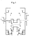
- FIG. 1 shows an inverse series connection of two translation units 19, 20, each of these two units in itself having a basic structure, as shown, for example, in French patent application No. 88 12 584 and described in terms of its function.
- the first transmission unit 19 has a driving element 1, which can consist, for example, of a drive gear of a bicycle, and this driving element 1 is connected to a ring drum-shaped input member 2, which has a schematically indicated first ring raceway.
- the intermediate member 5, which is also rotatably mounted, is located on an eccentric element 25, the eccentricity e of which is adjustable with respect to the fixed axis 4.
- the pivot levers 6 thus each extend between the coupling elements 7 and the intermediate member 5 and run in a common plane.
- the pivot bearings 8, 9 assigned to the pivot levers 6 are shown schematically in the drawing.
- the coupling elements 7 are preferably designed as clamping shoes which can engage in the ring raceway 3 in a form-fitting and non-positive manner and are designed as pulling free-running and pushing-clamping elements, ie they can only transmit force in one running direction.
- the first intermediate member 5 represents the output of the first translation unit 19, and on the same eccentric element 25, on which this first intermediate member is located, a second intermediate member 17 is arranged, which represents the input member of the second translation unit 20.
- This second intermediate element 17 is in turn coupled to pivoting levers 13 carrying clamping shoes 14 with a second ring raceway 12, which is formed on a ring drum-shaped output element 11, which can form the driven element or is firmly connected to a driven element 10.
- pivot levers 13 are connected via bearings 15, 16 to the associated intermediate member 17 or the associated clamping shoes 14 and circulate in one plane over the circumference of the intermediate member 17.
- the described structure of the transmission according to the invention shows that, in contrast to known arrangements, this transmission is of central symmetry, which makes it possible to obtain fluctuations or speed fluctuations in the two successive translation units while maintaining a large translation range, which is caused by the product of the individual translations of the two translation units is intended to be minimized.
- the fluctuations can be significantly reduced by the coupling elements 14 of the second transmission unit with respect to the coupling elements 7 of the first transmission unit 19 with regard to their non-positive engagement with the associated ring raceway 3 or 12 are angularly offset such that the speed maxima of the first stage 19 are at least substantially in phase with the speed minima of the second stage.
- the product formation with regard to the translation achieved by the inverse series connection results in a homogenization of the transmission characteristic, an optimization being possible in that the lever arms and the eccentricity of the second translation unit are selected relative to the first translation unit such that the speed fluctuations in both translation units are at least essentially the same in size.
- a continuously variable transmission of the type shown in FIG. 1 in its basic structure can be used in a wide variety of fields of application, such as, for example, in mechanically or electrically driven machines, motor vehicles and the like.
- An advantageous application is the use in bicycles, where this gearbox is particularly space-saving render version can easily be accommodated in a rear wheel hub.
- FIG. 2 shows an axial section of a rear wheel hub of a vehicle with an integrated continuously variable transmission according to the invention.
- the same reference numerals as in Fig. 1 are used for corresponding parts for easier understanding.
- This drum-shaped part 2 is rotatably supported by a ball bearing with respect to a fixed axis 4 and is provided with the first ring raceway 3 in the region of its inner wall.
- This ring raceway 3 interacts with coupling elements 7 in the form of clamping shoes effective in one running direction, which are pivotably or tiltably mounted at one end of pivoting levers 6 by means of bearings 9.
- the other end of each pivot lever 6 is attached via a pivot bearing 8 to a first intermediate member 5 which is rotatably mounted on an eccentric element 25 with the interposition of a bearing 34.
- the coupling elements 7 can be supported on a raceway 23 via a respective bearing member 22.
- a second intermediate member 17 is also rotatable and fixedly connected to the first intermediate member 25, which is also annular and carries pivot levers 13 via pivot bearings 15, at the other end of which pivot attachments 16 are attached to second coupling elements 14, which in turn interact with a ring raceway 12 which is provided on an output member 11.
- This rotatably mounted output member 11 is firmly screwed to a hub drum part which forms the driven element 10. Fastening rings for the spokes of the rear wheel can be attached to this hub drum part.
- the desired transmission ratio is set by adjusting the eccentric element 25 relative to the fixed axis 4.
- the disc-shaped eccentric element 25 is arranged between two plate-shaped limiting members 30, 31, which are fixed at their mutual spacing by spacer bolts, one of these bolts simultaneously forming a fixed pivot axis 28 for the eccentric element 25.
- the limiting member 30 is fixed via a cylindrical extension 35 with respect to the axis 4, and an actuating sleeve 24 runs radially inside this cylindrical extension 35, which is connected at its outer end to an operating lever 33 and has a fork 26 at its inner end, which between the limiting member 30 and the eccentric element 25 engages and is coupled to a side pin 27 of this eccentric element.
- the eccentric element 25 By pivoting the fork 26, the eccentric element 25 can be pivoted about the fixed axis 28, as a result of which an eccentric position is created between the axis of rotation 18 of the rotating intermediate members 5, 17 and the fixed axis 4 indicated in FIG. 1, and thus the transmission ratio is changed.
- the transmission and power transmission characteristics of this continuously operating transmission can be influenced and optimized by various parameters.
- FIG. 3 shows a section through the first transmission unit of the transmission according to FIG. 2, this unit being in the centered state, in which the fixed axis 4 coincides with the eccentric axis and the transmission ratio of this stage is 1: 1.
- the arrangement in this embodiment is preferably such that in this centered state both pivot bearings 8, 9 of the pivot lever 6 are on the same circle.
- pivot bearings 15 of the pivot levers assigned to the second transmission unit are located on a somewhat larger radius R2.
- a first part-circular recess 24 for the fixed axis 4 and a second part-circular recess 32 for a fastening and spacing bolt in the eccentric element 25 are provided.
- FIG. 4 shows the first translation unit according to FIG. 3 in the state of maximum eccentricity.
- the eccentric element 25 has been pivoted about the fixed axis 28 by means of the fork 26, so that the axis 18 of this eccentric element 25 is now eccentric with respect to the fixed axis 4, as is also shown schematically in FIG. 1.
- Fig. 5 shows a section through the central plane of the coupling elements of the second translation unit, wherein this second translation unit is also in the state of maximum eccentricity.
- the driven element 10 is fixedly connected to the output member 11, which is rotatably supported with respect to the axis 4 via a needle bearing 36 and in which the second ring raceway 12 is formed, in which the coupling elements 14 engage.
- the coupling elements 14 and thus also the pivot levers 13 are force-transmitting only within a defined angular range and are idle outside this angular range.
- the force-transmitting angular range of this second transmission unit is angularly offset with respect to the force-transmitting angular range of the first transmission unit, and this makes it possible to largely average out the fluctuations or speed fluctuations that occur in the two successive transmission units, so that a uniform power transmission largely free of fluctuations is ensured.
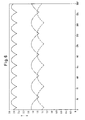
- FIG. 6 shows in diagram form the interaction between the first and second translation unit in the context of the inverse series connection according to the invention.
- the resulting translations are plotted on the ordinate on the ordinate on the abscissa.
- the first translation unit is assigned the dashed and the second translation unit the dash-dotted curve, while the entire translation is shown in the form of a solid curve.
- the entire translation is the product of the individual translations achieved in the two stages, and it can clearly be seen that these fluctuations occurring on the output side are significantly less than the fluctuations of the individual stages and practically no longer appear disruptive.
Abstract
Description
Die Erfindung betrifft ein stufenloses Getriebe gemäß dem Oberbegriff des Patentanspruches 1.The invention relates to a continuously variable transmission according to the preamble of
Ein derartiges Getriebe ist aus der EP-A2-280 481 bekannt und weist zwei Übersetzungsstufen auf, die zwischen dem antreibenden und einem anzutreibenden Element in Serie geschaltet sind. Das antreibende Element wird bei diesem bekannten Getriebe von der Pedalkurbel eines Fahrrads und das anzutreibende Element von einem dieser Pedalkurbel zugeordneten Zahnkranz gebildet.
Bei allen bekannten stufenlosen Getrieben dieser Art, und zwar auch bei einstufigen Getrieben besteht das Problem, daß aufgrund des jeweils aufeinanderfolgend stattfindenden kraftschlüssigen Eingriffs der Kuppelelemente Geschwindigkeitsschwankungen auftreten, die Torsionsschwingungen verursachen können und unerwünschte Belastungen sowie störende Geräusche zur Folge haben können. Bei Verwendung derartiger stufenloser Getriebe bei Fahrrädern können diese Fluktuationen während des Tretvorgangs auch als störend ruckartig aufeinanderfolgende Bewegungsschwankungen empfunden werden.Such a transmission is known from EP-A2-280 481 and has two transmission stages which are connected in series between the driving element and an element to be driven. In this known transmission, the driving element is formed by the pedal crank of a bicycle and the element to be driven is formed by a ring gear assigned to this pedal crank.
In all known continuously variable transmissions of this type, even with single-stage transmissions, there is the problem that, due to the successive non-positive engagement of the coupling elements, speed fluctuations occur which can cause torsional vibrations and can lead to undesirable loads and disturbing noises. When using such a continuously variable transmission in bicycles, these fluctuations during the pedaling process can also be felt as disturbing jerky successive movement fluctuations.
Diese bei derartigen Getrieben auftretenen Fluktuationen hängen ab von der Auslegung bzw. Geometrie des jeweiligen Getriebes und insbesondere auch von der Anzahl der verwendeten Übertragungselemente in Form von mit Kuppelelementen versehenen Schwenkhebeln. Je größer die Anzahl solcher Schwenkhebel gewählt werden kann, desto geringer werden die erwähnten Schwankungen, aber eine Erhöhung der Anzahl der Schwenkhebel und Kuppelelemente führt nicht nur zu einer wesentlichen Kostenerhöhung, sondern vor allem auch zu einer Verkomplizierung der Gesamtkonstruktion und auch zu einer Erhöhung des Raumbedarfs, was bei vielen Anwendungsfällen nicht akzepta bel ist. Weiterhin wird von derartigen Getrieben ein möglichst großer Übersetzungsbereich gefordert, wobei im Falle der Verwendung eines einstufigen Getriebes konstruktive Grenzen gegeben sind.
Um den Übersetzungsbereich zu vergrößern, sind gemäß EP-A2-280 481 zwei Übersetzungsstufen in Serie geschaltet. Auf diese Weise gelingt es zwar, einen größeren Übersetzungsbereich zu erhalten, da die mit einer derartigen Serienschaltung erreichbare Gesamtübersetzung etwa dem Produkt der Übersetzungsverhältnisse der beiden Einzelstufen entspricht, aber dabei zeigt sich der wesentliche Nachteil, daß bei einer derartigen Serienschaltung sehr große aperiodische Fluktuationen bzw. Übersetzungsschwankungen im Übertragungsweg zwischen Eingangs- und Ausgangsorgan auftreten.These fluctuations occurring in such transmissions depend on the design or geometry of the respective transmission and in particular also on the number of transmission elements used in the form of pivot levers provided with coupling elements. The greater the number of such pivoting levers that can be selected, the smaller the fluctuations mentioned, but an increase in the number of pivoting levers and coupling elements not only leads to a significant increase in costs, but above all to a complication of the overall construction and also to an increase in the space requirement , which is not acceptable in many applications is. Such gears are also required to have the largest possible gear ratio range, and there are design limits when a single-stage gear is used.
In order to enlarge the translation range, two translation stages are connected in series in accordance with EP-A2-280 481. In this way, it is possible to obtain a larger translation range, since the overall translation that can be achieved with such a series connection corresponds approximately to the product of the translation ratios of the two individual stages, but this shows the essential disadvantage that very large aperiodic fluctuations or Translation fluctuations occur in the transmission path between the input and output element.
Aufgabe der Erfindung ist es, ein stufenloses Getriebe der eingangs angegebenen Art bei geringem konstruktiven Aufwand in der Weise auszubilden, daß einerseits ein hoher Übersetzungsbereich erzielt werden kann und andererseits die Fluktuationen bzw. Schwankungen im Übertragungsweg zwischen Eingangsorgan und Ausgangsorgan minimiert und somit störende Auswirkungen derartiger Fluktuationen praktisch ausgeschaltet werden. Außerdem soll das Getriebe einen geringen Raumbedarf besitzen, keine störenden Geräusche entwickeln und geeignet sein, große Kräfte bzw. Momente zu übertragen.The object of the invention is to design a continuously variable transmission of the type specified at the outset with little design effort in such a way that on the one hand a high translation range can be achieved and on the other hand the fluctuations or fluctuations in the transmission path between the input member and the output member are minimized and thus disturbing effects of such fluctuations practically be turned off. In addition, the gearbox should have a small footprint, not generate any disturbing noises and should be suitable for transmitting large forces or moments.
Ausgehend von dem im Oberbegriff des Patentanspruches 1 beschriebenen stufenlosen Getriebe wird diese Aufgabe nach der Erfindung dadurch gelöst, daß die Übersetzungseinheiten paarweise invers zusammengefaßt sind und jedes Einheitenpaar eine entweder die Organe mit den Ringlaufbahnen oder die Organe mit den Kuppelelementen gemeinsam betätigende Exzenter-Stellvorrichtung aufweist.Starting from the continuously variable transmission described in the preamble of
Durch die inverse Reihenschaltung zweier Übersetzungseinheiten wird eine prinzipiell mittensymmetrische Anordnung erhalten, wobei das Ausgangsorgan der ersten Stufe und das Eingangsorgan der zweiten Stufe gleiche Periode und gleiche Winkelgeschwindigkeiten besitzen.The inverse series connection of two translation units results in a basically symmetrical arrangement, the output member of the first stage and the input member of the second stage having the same period and the same angular velocities.
Die zweite Übersetzungsstufe wird vorzugsweise so ausgelegt, daß die sich über 360° ergebenden Fluktuationen bzw. Geschwindigkeitsschwankungen beider Übertragungsstufen sehr ähnlich und vorzugsweise identisch sind.
Wenn dann gemäß einer weiteren Besonderheit der Erfindung zwischen den beiden Übersetzungsstufen die jeweiligen Kraftübertragungsbereiche, bei denen die Kuppelorgane kraftschlüssig klemmend mit der jeweils zugeordneten Ringlaufbahn in Eingriff treten, winkelmäßig derart gegeneinander versetzt werden, daß die Geschwindigkeitsmaximas der ersten Stufe zumindest im wesentlichen in Phase sind mit den Geschwindigkeitsminimas der zweiten Stufe, dann werden hinsichtlich der Geschwindigkeitsschwankungen bzw. Fluktuationen Optimalwerte erhalten.The second transmission stage is preferably designed in such a way that the fluctuations or speed fluctuations of the two transmission stages which result over 360 ° are very similar and preferably identical.
If, according to a further special feature of the invention, the respective power transmission areas, in which the coupling elements engage in a force-locking manner with the respectively assigned ring raceway, are angularly offset from one another in such a way that the speed maxima of the first stage are at least essentially in phase with the speed minima of the second stage, then optimal values are obtained with regard to the speed fluctuations or fluctuations.
Die durch die Erfindung ermöglichte, zumindest weitestgehende Ausschaltung störender Geschwindigkeitsschwankungen führt auch zu einer Optimierung der Übertragungseigenschaften eines derartigen stufenlosen Getriebes, da bei Gewährleistung eines großen Übersetzungsbereichs störende Torsionsschwingungen und Geräuschbildungen vermieden und gleichzeitig hohe Übertragungsleistungen sichergestellt werden können.The, at least as far as possible, elimination of disturbing speed fluctuations, which is made possible by the invention, also leads to an optimization of the transmission properties of such a continuously variable transmission, since while ensuring a large transmission range, disturbing torsional vibrations and noise formation can be avoided and high transmission powers can be ensured at the same time.
Besonders vorteilhafte Ausgestaltungen der Erfindung sind in den Unteransprüchen angegeben.Particularly advantageous embodiments of the invention are specified in the subclaims.
Die Erfindung wird nachfolgend unter Bezugnahme auf die Zeichnung näher erläutert; in der Zeichnung zeigt:
- Fig. 1 eine schematische Darstellung zur Erläuterung des prinzipiellen Aufbaus eines stufenlosen Getriebes nach der Erfindung,
- Fig. 2 eine Axialschnittdarstellung einer Ausführungsform eines zweistufigen Getriebes nach der Erfindung, das in die Hinterradnabe eines Fahrrads integriert ist,
- Fig. 3 eine Querschnittsdarstellung des Getriebes nach Fig. 2, wobei der Schnitt durch die erste Übersetzungseinheit verläuft, die sich in der zentrierten Stellung befindet,
- Fig. 4 eine der Schnittdarstellung nach Fig. 3 entsprechende Darstellung, wobei sich die erste Exzentereinheit jedoch in der maximal exzentrischen Stellung befindet,
- Fig. 5 eine Querschnittsdarstellung des Getriebes nach Fig. 2, wobei die Schnittebene durch die zweite Übersetzungseinheit verläuft, welche sich in der maximal exzentrischen Position befindet, und
- Fig. 6 eine schematische Diagrammdarstellung zur Erläuterung des Zusammenwirkens der beiden Übersetzungseinheiten im Hinblick auf die Minimierung von Fluktuationen.
- 1 is a schematic representation to explain the basic structure of a continuously variable transmission according to the invention,
- 2 is an axial sectional view of an embodiment of a two-stage transmission according to the invention, which is integrated into the rear wheel hub of a bicycle,
- 3 shows a cross-sectional view of the transmission according to FIG. 2, the section running through the first transmission unit, which is in the centered position,
- 4 shows a representation corresponding to the sectional view according to FIG. 3, the first eccentric unit, however, being in the maximum eccentric position,
- 5 shows a cross-sectional illustration of the transmission according to FIG. 2, the section plane running through the second transmission unit, which is in the maximum eccentric position, and
- 6 shows a schematic diagram to explain the interaction of the two translation units with a view to minimizing fluctuations.
Die schematische Darstellung nach Fig. 1 zeigt eine inverse Serienschaltung zweier Übersetzungseinheiten 19, 20, wobei jede dieser beiden Einheiten für sich betrachtet einen Grundaufbau besitzt, wie er beispielsweise in der französischen Patentanmeldung Nr. 88 12 584 dargestellt und in hinsichtlich seiner Funktion beschrieben ist.The schematic representation according to FIG. 1 shows an inverse series connection of two
Die erste Übersetzungseinheit 19 besitzt ein antreibendes Element 1, das beispielsweise aus einem Antriebszahnrad eines Fahrrads bestehen kann, und dieses antreibende Element 1 ist mit einem ringtrommelförmigen Eingangsorgan 2 verbunden, das eine schematisch angedeutete erste Ringlaufbahn besitzt. Mit dieser Ringlaufbahn 3 wirken mehrere über den Umfang verteilte, an Schwenkhebeln 6 gelagerte Kuppelelemente 7 zusammen, wobei die an einem Ende jeweils ein Kuppelelement 7 tragenden Schwenkhebel 6 mit ihrem anderen Ende an einem ersten Zwischenorgan 5 gelagert sind. Das ebenfalls drehbar gelagerte Zwischenorgan 5 befindet sich auf einem Exzenterelement 25, dessen Exzentrizität e bezogen auf die feste Achse 4 einstellbar ist.The
Die Schwenkhebel 6 erstrecken sich somit jeweils zwischen den Kuppelelementen 7 und dem Zwischenorgan 5 und laufen in einer gemeinsamen Ebene um. Die den Schwenkhebeln 6 zugeordneten Schwenklager 8, 9 sind in der Zeichnung schematisch dargestellt.The pivot levers 6 thus each extend between the
Die Kuppelelemente 7 sind vorzugsweise als Klemmschuhe ausgebildet, die form- und kraftschlüssig in die Ringlaufbahn 3 eingreifen können und als ziehend freilaufende und stoßend klemmende Elemente ausgebildet sind, d.h. nur in einer Laufrichtung kraftübertragend wirksam werden können.The
Das erste Zwischenorgan 5 stellt den Ausgang der ersten Übersetzungseinheit 19 dar, und auf dem gleichen Exzenterelement 25, auf dem sich dieses erste Zwischenorgan befindet, ist ein zweites Zwischenorgan 17 angeordnet, das das Eingangsorgan der zweiten Übersetzungseinheit 20 darstellt.The first
Dieses zweite Zwischenorgan 17 ist wiederum über Klemmschuhe 14 tragende Schwenkhebel 13 mit einer zweiten Ringlaufbahn 12 gekuppelt, die an einem ringtrommelförmigen Ausgangsorgan 11 ausgebildet ist, welches das angetriebene Element bilden kann oder fest mit einem angetriebenen Element 10 verbunden ist.This second
In gleicher Weise wie in der ersten Übersetzungseinheit 19 sind auch in der zweiten Übersetzungseinheit 20 die Schwenkhebel 13 über Lager 15, 16 mit dem zugeordneten Zwischenorgan 17 bzw. den zugeordneten Klemmschuhen 14 verbunden und laufen über den Umfang des Zwischenorgans 17 verteilt in einer Ebene um.In the same way as in the
Der beschriebene Aufbau des erfindungsgemäßen Getriebes zeigt, daß dieses Getriebe im Gegensatz zu bekannten Anordnungen mittensymmetrisch ausgebildet ist, wodurch es möglich wird, die sich in den beiden aufeinanderfolgenden Übersetzungseinheiten funktionsbedingt ergebenden Fluktuationen bzw. Geschwindigkeitsschwankungen unter Beibehaltung eines großen Übersetzungsbereichs, der durch das Produkt der Einzelübersetzungen der beiden Übersetzungseinheiten bestimmt ist, zu minimieren.The described structure of the transmission according to the invention shows that, in contrast to known arrangements, this transmission is of central symmetry, which makes it possible to obtain fluctuations or speed fluctuations in the two successive translation units while maintaining a large translation range, which is caused by the product of the individual translations of the two translation units is intended to be minimized.
Die Fluktuationen oder Geschwindigkeitsschwankungen sind bei Getrieben dieser Art bekanntlich eine Folge davon, daß in Abhängigkeit von der eingestellten Exzentrizität, die maßgebend für das jeweilige Übersetzungsverhältnis ist, die Kup plungselemente jeweils nur während eines Teilbereichs ihres gesamten Umlaufs über 360° in kraftschlüssigen Eingriff mit der zugeordneten Ringlaufbahn kommen. Es müssen also die Kupplungselemente nacheinander die Funktion der Kraft- bzw. Momentenübertragung übernehmen und dieses Ein- und Auskoppeln der einzelnen Kuppelelemente sowie die Aufeinanderfolge dieser Kuppelelemente führt zu gewissen Fluktuationen bzw. Geschwindigkeitsschwankungen, die generell unerwünscht sind.The fluctuations or speed fluctuations in transmissions of this type are known to be a consequence of the fact that, depending on the set eccentricity, which is decisive for the respective transmission ratio, the Kup plunging elements only come into non-positive engagement with the associated ring track during a partial area of their entire circulation over 360 °. The coupling elements must therefore take over the function of force or torque transmission one after the other, and this coupling and uncoupling of the individual coupling elements and the succession of these coupling elements leads to certain fluctuations or speed fluctuations, which are generally undesirable.
Durch die inverse Serienschaltung von zwei Übersetzungseinheiten, wie sie in Fig. 1 dargestellt ist, lassen sich die Fluktuationen wesentlich verringern, indem die Kuppelelemente 14 der zweiten Übertragungseinheit bezüglich der Kuppelelemente 7 der ersten Übertragungseinheit 19 bezüglich ihres kraftschlüssigen Eingriffs mit der jeweils zugehörigen Ringlaufbahn 3 bzw. 12 winkelmäßig derart versetzt werden, daß die Geschwindigkeitsmaxima der ersten Stufe 19 zumindest im wesentlichen in Phase sind mit den Geschwindigkeitsminima der zweiten Stufe. Durch die sich durch die inverse Serienschaltung ergebende Produktbildung hinsichtlich der erzielten Übersetzung ergibt sich auf diese Weise eine Vergleichmäßigung der Übertragungscharakteristik, wobei eine Optimierung dadurch möglich ist, daß die Hebelarme und die Exzentrizität der zweiten Übersetzungseinheit relativ zur ersten Übersetzungseinheit derart gewählt werden, daß die Geschwindigkeitsschwankungen in beiden Übersetzungseinheiten in ihrer Größe zumindest im wesentlichen gleich sind.By the inverse series connection of two translation units, as shown in Fig. 1, the fluctuations can be significantly reduced by the
Ein stufenloses Getriebe der in Fig. 1 in seinem grundsätzlichen Aufbau gezeigten Art kann in den unterschiedlichsten Anwendungsgebieten, wie z.B. bei mechanisch oder elektrisch angetriebenen Maschinen, Motorfahrzeugen und dergleichen eingesetzt werden. Ein vorteilhafter Anwendungsfall ist der Einsatz bei Fahrrädern, wo dieses Getriebe in besonders raumspa render Ausführung problemlos in einer Hinterradnabe untergebracht werden kann.A continuously variable transmission of the type shown in FIG. 1 in its basic structure can be used in a wide variety of fields of application, such as, for example, in mechanically or electrically driven machines, motor vehicles and the like. An advantageous application is the use in bicycles, where this gearbox is particularly space-saving render version can easily be accommodated in a rear wheel hub.
Fig. 2 zeigt einen Axialschnitt einer Hinterradnabe eines Fahrzeugs mit integriertem stufenlosen Getriebe gemäß der Erfindung. In dieser Darstellung sind zum leichteren Verständnis die gleichen Bezugszeichen wie in Fig. 1 für einander entsprechende Teile verwendet.2 shows an axial section of a rear wheel hub of a vehicle with an integrated continuously variable transmission according to the invention. In this illustration, the same reference numerals as in Fig. 1 are used for corresponding parts for easier understanding.
Ein über eine Kette antreibbares Element 1 in Form eines Zahnrads ist mit einem Flansch eines trommelförmigen Teils 2 fest verschraubt, das das Eingangsorgan des Getriebes bildet. Dieses trommelförmige Teil 2 ist über ein Kugellager bezüglich einer festen Achse 4 drehbar gelagert und im Bereich seiner Innenwandung mit der ersten Ringlaufbahn 3 versehen.An
Diese Ringlaufbahn 3 wirkt mit Kuppelelementen 7 in Form von in einer Laufrichtung wirksamen Klemmschuhen zusammen, welche an einem Ende von Schwenkhebeln 6 mittels Lagern 9 verschwenk bzw. kippbar gelagert sind. Das jeweils andere Ende eines jeden Schwenkhebels 6 ist über ein Schwenklager 8 an einem ersten Zwischenorgan 5 befestigt, das unter Zwischenschaltung eines Lagers 34 drehbar auf einem Exzenterelement 25 angebracht ist.This
Zweckmäßigerweise sind fünf über den Umfang verteilte Schwenkhebel 6 mit zugeordneten Kuppelelementen 7 verwendet.Five pivot levers 6 distributed over the circumference with associated
Die Kuppelelemente 7 sind bei der gezeigten Ausführungsform über jeweils ein Lagerorgan 22 auf einer Laufbahn 23 abstützbar.In the embodiment shown, the
Analog dem ersten Zwischenorgan 5 ist ebenfalls drehbar und mit dem ersten Zwischenorgan fest verbunden auf dem Exzenterelement 25 ein zweites Zwischenorgan 17 angebracht, das ebenfalls ringförmig ausgebildet ist und über Schwenklager 15 Schwenkhebel 13 trägt, an deren jeweils anderem Ende über Schwenklager 16 zweite Kuppelelemente 14 angebracht sind, die wiederum mit einer Ringlaufbahn 12 zusammenwirken, die an einem Ausgangsorgan 11 vorgesehen ist. Dieses drehbar gelagerte Ausgangsorgan 11 ist fest mit einem Nabentrommelteil verschraubt, das das angetriebene Element 10 bildet. An diesem Nabentrommelteil können Befestigungsringe für die Speichen des Hinterrads angebracht werden.Analogously to the first
Die Einstellung der jeweils gewünschten Übersetzung erfolgt durch Verstellen des Exzenterelements 25 relativ zur festen Achse 4.The desired transmission ratio is set by adjusting the
Das scheibenförmig ausgebildete Exzenterelement 25 ist zwischen zwei plattenförmigen Begrenzungsorganen 30, 31 angeordnet, welche in ihrem gegenseitigen Abstand durch Distanzbolzen festgelegt sind, wobei einer dieser Bolzen gleichzeitig eine feste Schwenkachse 28 für das Exzenterelement 25 bildet. Das Begrenzungsorgan 30 ist über einen zylinderförmigen Ansatz 35 bezüglich der Achse 4 festgelegt, und radial innerhalb dieses zylindrischen Ansatzes 35 verläuft eine Betätigungshülse 24, die an ihrem außenliegenden Ende mit einem Betätigungshebel 33 verbunden ist und an ihrem innenliegenden Ende eine Gabel 26 aufweist, die zwischen das Begrenzungsorgan 30 und das Exzenterelement 25 eingreift und mit einem Seitenzapfen 27 dieses Exzenterelementes gekuppelt ist. Durch Verschwenken der Gabel 26 kann das Exzenterelement 25 um die feste Achse 28 verschwenkt werden, wodurch zwischen der in Fig. 1 angedeuteten Drehachse 18 der rotierenden Zwischenorgane 5, 17 und der festen Achse 4 eine exzentrische Position geschaffen und damit das Übersetzungsverhältnis geändert wird.The disc-shaped
Die Übersetzungs- und Kraftübertragungscharakteristiken dieses stufenlos arbeitenden Getriebes können durch verschiedene Parameter beeinflußt und optimiert werden.The transmission and power transmission characteristics of this continuously operating transmission can be influenced and optimized by various parameters.
Von wesentlicher Bedeutung sind dabei die Wahl der Durchmesser der Ringlaufbahnen 3, 12, die Wahl der Durchmesser der Schwenklagerkreise für die Schwenkhebel 6, 13 an den Zwischenorganen 5, 17 sowie die Länge der Schwenkhebel und die einstellbaren Exzentrizitäten. Ferner ist von ganz wesentlicher Bedeutung die Winkelversetzung zwischen den Kuppelelementen 7 bzw. 14 in den beiden Stufen des Getriebes, da es durch diese Winkelversetzung möglich ist, die Fluktuationen zu minimieren.The choice of the diameter of the
Fig. 3 zeigt einen Schnitt durch die erste Übersetzungseinheit des Getriebes nach Fig. 2, wobei sich diese Einheit im zentrierten Zustand befindet, in dem die feste Achse 4 mit der Exzenterachse zusammenfällt und das Übersetzungsverhältnis dieser Stufe 1 : 1 beträgt. Das ringförmige Zwischenorgan 5, das über das Lager 34 drehbar auf dem Exzenterelement 25 angeordnet ist, liegt dabei konzentrisch zur festen Achse 4, und demgemäß ist auch der Kreis vom Radius R1 konzentrisch zur festen Achse 4, auf dem die Schwenklager 8 für die Schwenkhebel 6 gelegen sind, an deren anderen Ende über Lager 9 die Kuppelelemente 7 angebracht sind. Die Anordnung ist bei dieser Ausgestaltung vorzugsweise so getroffen, daß sich in diesem zentrierten Zustand beide Schwenklager 8, 9 der Schwenkhebel 6 auf dem gleichen Kreis befinden.3 shows a section through the first transmission unit of the transmission according to FIG. 2, this unit being in the centered state, in which the fixed
Es ist in Fig. 3 auch zu sehen, daß die Schwenklager 15 der der zweiten Übersetzungseinheit zugeordneten Schwenkhebel auf einem etwas größeren Radius R2 gelegen sind.It can also be seen in FIG. 3 that the
Die zur Exzenter-Stellvorrichtung gehörende und mit der Betätigungshülse 24 verbundene Gabel 26 umgreift den Seitenzapfen 27 des Exzenterelements 25, das um die feste Achse 28 verschwenkbar ist. Um diese Verschwenkung zu ermöglichen, ist eine erste teilkreisförmige Ausnehmung 24 für die feste Achse 4 und eine zweite teilkreisförmige Ausnehmung 32 für einen Befestigungs- und Distanzbolzen im Exzenterelement 25 vorgesehen.The
Wird die Gabel 26 im Uhrzeigersinn verschwenkt, dann führt dies zu einer exzentrischen Position des Exzenterelements 21 relativ zur festen Achse 4 und damit zu einer Erhöhung des Übersetzungsverhältnisses.If the
Fig. 4 zeigt die erste Übersetzungseinheit nach Fig. 3 im Zustand maximaler Exzentrizität. Dazu ist mittels der Gabel 26 das Exzenterelement 25 um die feste Achse 28 verschwenkt worden, so daß nunmehr die Achse 18 dieses Exzenterelements 25 bezüglich der festen Achse 4 exzentrisch liegt, wie dies schematisch auch in Fig. 1 gezeigt ist.FIG. 4 shows the first translation unit according to FIG. 3 in the state of maximum eccentricity. For this purpose, the
Aufgrund dieser exzentrischen Lage ergeben sich über den Umlaufwinkel von 360° betrachtet unterschiedliche Abstände zwischen den Schwenklagern 9 der Schwenkhebel 6 am Zwischenorgan 5 und der Ringlaufbahn 3, was zur Folge hat, daß die Kuppelelemente 7 nur noch auf einem begrenzten, definierten Winkelbereich nacheinander kraftübertragend wirksam werden und außerhalb dieses Bereichs die Kuppelelemente im Leerlaufzustand sind.
Dieses Funktionsprinzip ist im Detail in der französischen Patentanmeldung 88 12 584 beschrieben.Because of this eccentric position, there are different distances between the
This principle of operation is described in detail in French patent application 88 12 584.
Fig. 5 zeigt einen Schnitt durch die Mittelebene der Kuppelelemente der zweiten Übersetzungseinheit, wobei sich diese zweite Übersetzungseinheit ebenfalls im Zustand maximaler Exzentrizität befindet.Fig. 5 shows a section through the central plane of the coupling elements of the second translation unit, wherein this second translation unit is also in the state of maximum eccentricity.
Das angetriebene Element 10 ist fest verbunden mit dem Ausgangsorgan 11, das über ein Nadellager 36 bezüglich der Achse 4 drehbar gelagert und in dem die zweite Ringlaufbahn 12 ausgebildet ist, in die die Kuppelelemente 14 eingreifen. Das zweite ringförmige Zwischenorgan 17, das in der bereits erläuterten Weise auf dem Exzenterelement angeordnet ist, liegt mit seiner Achse 18 bezüglich der festen Achse 4 exzentrisch, und damit ergeben sich für die Schwenkhebel 13 und die mit ihnen verbundenen Kuppelelemente 14 während des Umlaufs unterschiedliche Eingriffsverhältnisse bezüglich der Ringlaufbahn 12. Dies führt in gleicher Weise wie bereits im Zusammenhang mit der ersten Übersetzungseinheit erläutert dazu, daß die Kuppelelemente 14 und damit auch die Schwenkhebel 13 nur innerhalb eines definierten Winkelbereichs kraftübertragend wirksam sind und sich außerhalb dieses Winkelbereichs im Leerlauf befinden.The driven
Der kraftübertragend wirksame Winkelbereich dieser zweiten Übersetzungseinheit ist winkelmäßig bezüglich des kraftübertragenden Winkelbereichs der ersten Übersetzungseinheit versetzt angeordnet, und dadurch wird es möglich, die sich in den beiden aufeinanderfolgenden Übersetzungseinheiten ergebenden Fluktuationen bzw. Geschwindigkeitsschwankungen weitestgehend auszumitteln, so daß eine gleichförmige, von Schwankungen weitestgehend befreite Kraftübertragung sichergestellt ist.The force-transmitting angular range of this second transmission unit is angularly offset with respect to the force-transmitting angular range of the first transmission unit, and this makes it possible to largely average out the fluctuations or speed fluctuations that occur in the two successive transmission units, so that a uniform power transmission largely free of fluctuations is ensured.
Fig. 6 zeigt in Diagrammform das Zusammenwirken zwischen erster und zweiter Übersetzungseinheit im Rahmen der inversen Serienschaltung nach der Erfindung.6 shows in diagram form the interaction between the first and second translation unit in the context of the inverse series connection according to the invention.
Dabei sind über dem auf der Ordinate aufgetragenen Umlaufwinkel auf der Abszisse die sich ergebenden Übersetzungen aufgetragen. Der ersten Übersetzungseinheit ist dabei die strichlierte und der zweiten Übersetzungseinheit die strichpunktierte Kurve zugeordnet, während die gesamte Übersetzung in Form einer ausgezogenen Kurve dargestellt ist.The resulting translations are plotted on the ordinate on the ordinate on the abscissa. The first translation unit is assigned the dashed and the second translation unit the dash-dotted curve, while the entire translation is shown in the form of a solid curve.
Deutlich zu erkennen sind die sich in den beiden Übersetzungsstufen ergebenden Fluktuationen, die von den aufeinanderfolgenden Eingriffen der Kuppelelemente innerhalb eines bestimmten Winkelbereichs an der zugeordneten Ringlaufbahn herrühren.The fluctuations resulting in the two gear ratios, which result from the successive interventions of the coupling elements within a certain angular range on the assigned ring raceway, can be clearly seen.
Die gesamte Übersetzung stellt das Produkt der in den beiden Stufen erzielten Einzelübersetzungen dar, und es ist deutlich zu sehen, daß diese ausgangsseitig auftretenden Fluktuationen entscheidend geringer sind als die Fluktuationen der Einzelstufen und praktisch auch nicht mehr störend in Erscheinung treten.The entire translation is the product of the individual translations achieved in the two stages, and it can clearly be seen that these fluctuations occurring on the output side are significantly less than the fluctuations of the individual stages and practically no longer appear disruptive.
Dies ist eine Folge der inversen Serienschaltung, die zu einer Mittensymmetrie führt und es ermöglicht, die zweite Übersetzungseinheit bezüglich der ersten Übersetzungseinheit so auszugestalten und zu dimensionieren, daß die Fluktuationen identisch oder zumindest ähnlich sind, und die Winkelverschiebung zwischen den beiden Übersetzungseinheiten so zu wählen, daß die Maximas der Fluktuationen der ersten Übersetzungseinheit zumindest im Prinzip in Phase sind mit den Minimas der Fluktuationen der zweiten Stufe, wie dies in Fig. 6 gezeigt ist.This is a consequence of the inverse series connection, which leads to a center symmetry and makes it possible to design and dimension the second translation unit with respect to the first translation unit so that the fluctuations are identical or at least similar, and to choose the angular displacement between the two translation units, that the maximas of the fluctuations of the first translation unit are at least in principle in phase with the minimas of the fluctuations of the second stage, as shown in FIG. 6.
- 1 Antreibendes Element1 driving element
- 2 Eingangsorgan2 input organ
- 3 Erste Ringlaufbahn3 First ring track
- 4 Feste Achse4 Fixed axis
- 5 Erstes Zwischenorgan5 First intermediate body
- 6 Schwenkhebel6 swivel levers
- 7 Erstes Kuppelelement7 First coupling element
- 8 Schwenklager8 swivel bearings
- 9 Schwenklager9 swivel bearings
- 10 Angetriebenes Element10 Driven element
- 11 Ausgangsorgan11 exit organ
- 12 Zweite Ringlaufbahn12 Second ring track
- 13 Schwenkhebel13 swivel levers
- 14 Zweites Kuppelelement14 Second coupling element
- 15 Schwenklager15 swivel bearings
- 16 Schwenklager16 swivel bearings
- 17 Zweites Zwischenorgan17 Second intermediate body
- 18 Achse18 axis
- 19 Erste Übersetzungseinheit19 First translation unit
- 20 Zweite Übersetzungseinheit20 Second translation unit
- 21 Exzenter-Stellvorrichtung21 eccentric adjusting device
- 22 Lagerorgan22 storage organ
- 23 Laufbahn23 career
- 24 Betätigungshülse24 actuating sleeve
- 25 Exzenterelement25 eccentric element
- 26 Gabel26 fork
- 27 Seitenzapfen27 side pins
- 28 Feste Achse28 Fixed axis
- 29 Ausnehmung29 recess
- 30 Begrenzungsorgan30 limiting device
- 31 Begrenzungsorgan31 limiting device
- 32 Ausnehmung32 recess
- 33 Betätigungshebel33 operating lever
- 34 Lager34 bearings
- 35 Zylindrischer Ansatz35 Cylindrical approach
- 36 Nadellager36 needle bearings
Claims (12)
dadurch gekennzeichnet,
daß die Übersetzungseinheiten (19, 20) paarweise invers zusammengefaßt sind und jedes Einheitenpaar (19, 20) eine entweder die Organe (2, 11) mit den Ringlaufbahnen (3, 12) oder die Organe (6, 13) mit den Kuppelelementen (7, 14) gemeinsam betätigende Exzenter-Stellvorrichtung (21) aufweist.1. Continuously variable transmission for bicycles, motor vehicles, machines and the like, consisting of a driving and a driven element, which are rotatably and coaxially mounted and connected to each other via at least two successive translation units, the driving element with the input member of the first translation unit and the driven one Element is connected to the output member of the last translation unit, and each translation unit has an output member that is axially parallel to the respective input member and can be displaced relative to it, and the input member and output member are each coupled via a plurality of pivoting levers, one end of which is connected to one of the two members over its circumference is pivotally mounted distributed and the other ends are provided with coupling elements effective in one direction of rotation, which depending on the eccentricity determining the translation between the axes v on each input organ and output organ come into frictional engagement with partial areas of a ring track provided on the other organ in each rotation in a common plane,
characterized by
that the translation units (19, 20) are combined in inverse pairs and each pair of units (19, 20) one either the organs (2, 11) with the ring raceways (3, 12) or the organs (6, 13) with the coupling elements (7 , 14) has a jointly actuating eccentric adjusting device (21).
dadurch gekennzeichnet,
daß das gleichzeitig das antreibende Element (1) bildende Eingangsorgan (2) eine erste Ringlaufbahn (3) und das das angetriebene Element (10) bildende Ausgangsorgan (11) eine zweite Ringlaufbahn (12) besitzt, daß die erste Ringlaufbahn (3) über erste, Kuppelelemente (7) tragende Schwenkhebel (6) mit einem ersten drehbar gelagerten Zwischenorgan (5) und die zweite Ringlaufbahn (12) über zweite, Kuppelelemente (14) tragende Schwenkhebel (13) mit einem zweiten drehbar gelagerten Zwischenorgan (17) verbunden ist, und daß die beiden Zwischenorgane (5, 17) in vorgebbarer Relativlage auf der gleichen Achse (18) gelagert und mittels der Exzenter-Stellvorrichtung (21) gemeinsam bezüglich der die gleiche feste Achse (4) aufweisenden Eingangs- und Ausgangsorgane (2, 11) verstellbar sind.2. Transmission according to claim 1,
characterized by
in that the input element (2) forming the driving element (1) has a first ring track (3) and the output element (11) forming the driven element (10) has a second ring track (12) that the first ring track (3) has a first Coupling arms (6) carrying coupling elements (7) are connected to a first rotatably mounted intermediate member (5) and the second ring raceway (12) is connected via second pivoting levers (13) carrying coupling elements (14) to a second rotatably mounted intermediate member (17), and that the two intermediate elements (5, 17) are mounted in a predeterminable relative position on the same axis (18) and by means of the eccentric adjusting device (21) together with respect to the input and output elements (2, 11) having the same fixed axis (4) are adjustable.
dadurch gekennzeichnet,
daß die Kuppelelemente (14) der zweiten Übersetzungseinheit (20) bezüglich der Kuppelelemente (7) der ersten Übersetzungseinheit (19) bezüglich ihres kraftschlüssigen Eingriffs mit der zugehörigen Ringlaufbahn (3; 12) winkelmäßig derart versetzt sind, daß die Geschwindigkeitsmaxima der ersten Stufe (19) zumindest im wesentlichen in Phase sind mit dem Geschwindigkeitsminima der zweiten Stufe (20).3. Transmission according to claim 1 or 2,
characterized by
that the coupling elements (14) of the second transmission unit (20) are angularly offset with respect to the coupling elements (7) of the first transmission unit (19) with respect to their frictional engagement with the associated ring raceway (3; 12) such that the speed maxima of the first stage (19 ) are at least essentially in phase with the speed minima of the second stage (20).
dadurch gekennzeichnet,
daß die Größe der Exzentrizitäten (e) der den beiden Übersetzungseinheiten (19, 20) zugeordneten Zwischenorgane (5, 17) unterschiedlich ist.4. Transmission according to one of the preceding claims,
characterized by
that the size of the eccentricities (e) of the intermediate members (5, 17) assigned to the two translation units (19, 20) is different.
dadurch gekennzeichnet,
daß die Größe der in den beiden Übersetzungseinheiten (19, 20) zwischen den Ringlaufbahnen (3, 12) und den Zwischenorganen (5, 17) wirksam werdenden Hebelarme unterschiedlich ist.5. Transmission according to one of the preceding claims,
characterized by
that the size of the lever arms taking effect in the two transmission units (19, 20) between the ring raceways (3, 12) and the intermediate members (5, 17) is different.
dadurch gekennzeichnet,
daß die Hebelarme und die Exzentrizität der zweiten Übersetzungseinheit (20) relativ zur ersten Übersetzungseinheit (19) derart gewählt sind, daß die Geschwindigkeitsschwankungen in beiden Übersetzungseinheiten (19, 20) in ihrer Größe zumindest im wesentlichen gleich sind.6. Transmission according to one of the preceding claims,
characterized by
that the lever arms and the eccentricity of the second translation unit (20) relative to the first translation unit (19) are selected such that the speed fluctuations in both translation units (19, 20) are at least substantially the same in size.
dadurch gekennzeichnet,
daß die Kuppelelemente (7, 14) aus Klemmschuhen bestehen und daß die Klemmschuhe in der ersten Übersetzungseinheit (19) konstruktiv unterschiedlich zu den Klemmschuhen in der zweiten Übersetzungseinheit (20) ausgebildet sind.7. Transmission according to one of the preceding claims,
characterized by
that the coupling elements (7, 14) consist of clamping shoes and that the clamping shoes in the first transmission unit (19) are constructed differently from the clamping shoes in the second transmission unit (20).
dadurch gekennzeichnet,
daß die Klemmschuhe als ziehend freilaufende und stoßend klemmende Elemente ausgebildet sind.8. Transmission according to one of the preceding claims,
characterized by
that the clamping shoes are designed as pulling free running and pushing clamping elements.
dadurch gekennzeichnet,
daß die Anzahl von Schwenkhebeln (6, 13) und Kuppelelementen (7, 14) in beiden Übersetzungseinheiten (19, 20) gleich ist.9. Transmission according to one of the preceding claims,
characterized by
that the number of pivot levers (6, 13) and coupling elements (7, 14) in both translation units (19, 20) is the same.
dadurch gekennzeichnet,
daß die die Kuppelemente (7, 14) tragenden und in den Schwenkhebeln (6, 13) gelagerten Achsen über ein Lagerorgan (22) auf einer zur festen Achse (4) koaxialen Laufbahn (23) abstützbar sind.10. Transmission according to one of the preceding claims,
characterized by
that the axles carrying the coupling elements (7, 14) and supported in the swivel levers (6, 13) can be supported on a bearing member (22) on a track (23) coaxial with the fixed axle (4).
dadurch gekennzeichnet,
daß die Exzenter-Verstellvorrichtung (21) eine auf der festen Achse (4) angeordnete Betätigungshülse (24) aufweist, die sich bis zu einem die beiden Zwischenorgane (5, 17) tragenden Exzenterelement (25) erstreckt und über eine Gabel (26) an einem Seitenzapfen (27) des Exzenterelements (25) angreift, welches um eine feste Achse (28) verschwenkbar gelagert ist und zumindest eine dieses Verschwenken ermöglichende teilkreisförmige Ausnehmung (29) zur Aufnahme der festen Achse (4) aufweist.11. Transmission according to one of the preceding claims,
characterized by
that the eccentric adjusting device (21) has an actuating sleeve (24) arranged on the fixed axis (4), which extends to an eccentric element (25) carrying the two intermediate members (5, 17) and via a fork (26) a side pin (27) of the eccentric element (25) engages, which is pivotally mounted about a fixed axis (28) and has at least one part-circular recess (29) that enables this pivoting to receive the fixed axis (4).
dadurch gekennzeichnet,
daß das Exzenterelement (25) zwischen zwei plattenförmigen, achsfesten Begrenzungsorganen (30, 31) angeordnet ist, deren gegenseitiger Abstand durch Distanzbolzen festgelegt ist, von denen einer die feste Schwenkachse (28) für das Exzenterelement (25) bildet und der andere eine teilkreisförmige Ausnehmung des Exzenterelements (25) durchsetzt, und daß die Gabel (26) zwischen ein Begrenzungsorgan (30) und das Exzenterelement (25) eingreift.12. Transmission according to claim 11,
characterized by
that the eccentric element (25) between two plate-shaped, axially fixed limiting members (30, 31) is arranged, the mutual distance between which is determined by spacer bolts, one of which forms the fixed pivot axis (28) for the eccentric element (25) and the other a part-circular recess of the eccentric element (25), and that the fork (26) engages between a limiting member (30) and the eccentric element (25).
Priority Applications (3)
| Application Number | Priority Date | Filing Date | Title |
|---|---|---|---|
| EP89114383A EP0411190A1 (en) | 1989-08-03 | 1989-08-03 | Infinitely variable transmission |
| US07/561,527 US5081877A (en) | 1989-08-03 | 1990-08-01 | Steplessly variable transmission |
| JP2205296A JPH03135897A (en) | 1989-08-03 | 1990-08-03 | Non-stage transmission |
Applications Claiming Priority (1)
| Application Number | Priority Date | Filing Date | Title |
|---|---|---|---|
| EP89114383A EP0411190A1 (en) | 1989-08-03 | 1989-08-03 | Infinitely variable transmission |
Publications (1)
| Publication Number | Publication Date |
|---|---|
| EP0411190A1 true EP0411190A1 (en) | 1991-02-06 |
Family
ID=8201714
Family Applications (1)
| Application Number | Title | Priority Date | Filing Date |
|---|---|---|---|
| EP89114383A Withdrawn EP0411190A1 (en) | 1989-08-03 | 1989-08-03 | Infinitely variable transmission |
Country Status (3)
| Country | Link |
|---|---|
| US (1) | US5081877A (en) |
| EP (1) | EP0411190A1 (en) |
| JP (1) | JPH03135897A (en) |
Cited By (2)
| Publication number | Priority date | Publication date | Assignee | Title |
|---|---|---|---|---|
| EP0494341A1 (en) * | 1990-12-21 | 1992-07-15 | Look S.A. | Gearing with a variable transmission ratio in particular for bicycles |
| DE19534556A1 (en) * | 1995-09-18 | 1997-03-20 | Klothilde Janker | Continuously variable transmission for bicycle |
Families Citing this family (12)
| Publication number | Priority date | Publication date | Assignee | Title |
|---|---|---|---|---|
| US5226859A (en) * | 1991-02-22 | 1993-07-13 | Pires Paul R | Continuously or infinitely variable transmission free of over-running clutches |
| ZA943555B (en) * | 1993-05-24 | 1995-01-23 | Atomic Energy South Africa | Transmission |
| US5632702A (en) * | 1995-07-05 | 1997-05-27 | Speed Control, Inc. | Continuously variable transmission |
| US6055878A (en) * | 1997-12-16 | 2000-05-02 | Speed Control, Inc. | Adjustable eccentric shift mechanisms |
| US6354976B1 (en) * | 1998-07-02 | 2002-03-12 | Speed Control, Inc. | Transmissions, transmission lock assemblies, methods of adjusting a gear ratio of a transmission, and methods of forming a transmission shift mechanism |
| US5964677A (en) * | 1998-07-02 | 1999-10-12 | Speed Control, Inc. | Shift mechanisms, lock assemblies and methods of adjusting a gear ratio of a transmission |
| AUPQ089799A0 (en) * | 1999-06-10 | 1999-07-01 | Aimbridge Pty Ltd | Transmission |
| US6425301B1 (en) | 2000-08-16 | 2002-07-30 | Howard D. Rubenstein | Continuously variable transmission |
| US20040003672A1 (en) * | 2000-09-18 | 2004-01-08 | Rubenstein Howard D. | Continuously variable transmission |
| DK1735547T3 (en) * | 2004-04-01 | 2010-08-23 | Bhsci Llc | Continuously variable transmission |
| JP5543529B2 (en) * | 2012-06-03 | 2014-07-09 | 稔 中川 | Planetary gear continuously variable transmission mechanism |
| TW201514057A (en) * | 2013-10-14 | 2015-04-16 | Chen zheng he | Two-wheel vehicle structure (2) |
Citations (7)
| Publication number | Priority date | Publication date | Assignee | Title |
|---|---|---|---|---|
| US2973653A (en) * | 1956-01-19 | 1961-03-07 | Riedl Franz | Infinitely variable gear |
| US3892139A (en) * | 1974-05-09 | 1975-07-01 | Harris Dynamics | Variable speed transmission |
| US3987682A (en) * | 1974-07-11 | 1976-10-26 | Cyclecentric Corporation | Variable speed transmission |
| GB2024964A (en) * | 1978-07-05 | 1980-01-16 | Whitehead Moto Fides Stabil | Steplessly-variable transmission |
| US4277986A (en) * | 1977-09-26 | 1981-07-14 | Avco Corporation | Stepless, variable stroke drive having a non-rotating cam |
| DE3300144A1 (en) * | 1983-01-04 | 1984-07-05 | Peter-Christian Dipl.-Ing. Dipl.-Kfm. 8035 Gauting Wolf | Variable speed gearing |
| EP0280481A2 (en) * | 1987-02-21 | 1988-08-31 | Bridgestone Cycle Co., Ltd. | Stepless speed change device |
Family Cites Families (5)
| Publication number | Priority date | Publication date | Assignee | Title |
|---|---|---|---|---|
| US2547453A (en) * | 1947-09-17 | 1951-04-03 | Joseph H Egy | Variable-speed transmission device |
| IT997028B (en) * | 1971-02-04 | 1975-12-30 | Bianchini Vasco | SPEED VARIATOR CONGEGNO WITH TINUO INCLUDING AN ECCENTRIC WITH VARIABLE ECCENTRICITY |
| US4505163A (en) * | 1980-05-23 | 1985-03-19 | Raimund Falkner | Mechanism with continuous adjustment for the transmission of a rotary motion between two coaxial shafts |
| US4712450A (en) * | 1985-02-09 | 1987-12-15 | Bridgestone Cycle Co., Ltd. | Stepless speed change device |
| FR2637035A1 (en) * | 1988-09-27 | 1990-03-30 | Look Sa | SPEED VARIATOR WITH FRICTION PADS BETWEEN OTHERS FOR CYCLES |
-
1989
- 1989-08-03 EP EP89114383A patent/EP0411190A1/en not_active Withdrawn
-
1990
- 1990-08-01 US US07/561,527 patent/US5081877A/en not_active Expired - Fee Related
- 1990-08-03 JP JP2205296A patent/JPH03135897A/en active Pending
Patent Citations (7)
| Publication number | Priority date | Publication date | Assignee | Title |
|---|---|---|---|---|
| US2973653A (en) * | 1956-01-19 | 1961-03-07 | Riedl Franz | Infinitely variable gear |
| US3892139A (en) * | 1974-05-09 | 1975-07-01 | Harris Dynamics | Variable speed transmission |
| US3987682A (en) * | 1974-07-11 | 1976-10-26 | Cyclecentric Corporation | Variable speed transmission |
| US4277986A (en) * | 1977-09-26 | 1981-07-14 | Avco Corporation | Stepless, variable stroke drive having a non-rotating cam |
| GB2024964A (en) * | 1978-07-05 | 1980-01-16 | Whitehead Moto Fides Stabil | Steplessly-variable transmission |
| DE3300144A1 (en) * | 1983-01-04 | 1984-07-05 | Peter-Christian Dipl.-Ing. Dipl.-Kfm. 8035 Gauting Wolf | Variable speed gearing |
| EP0280481A2 (en) * | 1987-02-21 | 1988-08-31 | Bridgestone Cycle Co., Ltd. | Stepless speed change device |
Cited By (2)
| Publication number | Priority date | Publication date | Assignee | Title |
|---|---|---|---|---|
| EP0494341A1 (en) * | 1990-12-21 | 1992-07-15 | Look S.A. | Gearing with a variable transmission ratio in particular for bicycles |
| DE19534556A1 (en) * | 1995-09-18 | 1997-03-20 | Klothilde Janker | Continuously variable transmission for bicycle |
Also Published As
| Publication number | Publication date |
|---|---|
| US5081877A (en) | 1992-01-21 |
| JPH03135897A (en) | 1991-06-10 |
Similar Documents
| Publication | Publication Date | Title |
|---|---|---|
| EP1650071B1 (en) | Drive arrangement | |
| EP0180748B1 (en) | Planetary gearbox | |
| AT409030B (en) | DEVICE FOR ADJUSTING A CAMSHAFT | |
| AT503360B1 (en) | GEAR ASSEMBLY FOR THE VARIABLE TORQUE DISTRIBUTION | |
| DE19716386C2 (en) | differential | |
| EP0411190A1 (en) | Infinitely variable transmission | |
| DE3134204A1 (en) | "DIFFERENTIAL GEARBOX" | |
| DE3006331A1 (en) | TRANSMISSION | |
| DE102005048611A1 (en) | Drive arrangement for vehicle has gearbox driven by engine, driven shaft connected by eccentric drive on driving shaft, idler on driven shaft, connecting element between eccentric gear and idler; driven shaft is driven axle of vehicle | |
| DE4321476C2 (en) | Stepless friction roller gear with toroidal friction discs | |
| EP2129568B1 (en) | Gear assembly for a vehicle steering device | |
| DE10353927B4 (en) | Axle assembly | |
| WO2019086064A1 (en) | Drive train comprising two separate shiftable gear mechanisms which are coupled by means of intermediate gear mechanisms | |
| DE3619340C2 (en) | ||
| EP2255104A1 (en) | Transmission | |
| DE102020200123A1 (en) | Spur gear differential and drive system | |
| EP3439929B1 (en) | Brake actuator | |
| EP3301323B1 (en) | Cycloid gear | |
| EP0066122A2 (en) | Differential gearing | |
| DE102018008464A1 (en) | Drive train with two separate, coupled by means of intermediate gear shift transmissions | |
| EP0432349A2 (en) | Transmission | |
| DE10014853C2 (en) | Axial stroke roller | |
| EP3704013A1 (en) | Drive train comprising two separate shiftable gear mechanisms which are coupled by means of intermediate gear mechanisms | |
| DE3937725A1 (en) | VISCOSITY COUPLING | |
| DE112005001329T5 (en) | Transmission for a motor vehicle and a method of manufacturing a transmission |
Legal Events
| Date | Code | Title | Description |
|---|---|---|---|
| PUAI | Public reference made under article 153(3) epc to a published international application that has entered the european phase |
Free format text: ORIGINAL CODE: 0009012 |
|
| AK | Designated contracting states |
Kind code of ref document: A1 Designated state(s): AT BE CH DE ES FR GB GR IT LI LU NL SE |
|
| RBV | Designated contracting states (corrected) |
Designated state(s): AT BE CH DE ES FR GB IT LI |
|
| 17P | Request for examination filed |
Effective date: 19910516 |
|
| 17Q | First examination report despatched |
Effective date: 19920928 |
|
| STAA | Information on the status of an ep patent application or granted ep patent |
Free format text: STATUS: THE APPLICATION IS DEEMED TO BE WITHDRAWN |
|
| 18D | Application deemed to be withdrawn |
Effective date: 19930629 |