EP0410620B1 - Dispensing package - Google Patents
Dispensing package Download PDFInfo
- Publication number
- EP0410620B1 EP0410620B1 EP90307775A EP90307775A EP0410620B1 EP 0410620 B1 EP0410620 B1 EP 0410620B1 EP 90307775 A EP90307775 A EP 90307775A EP 90307775 A EP90307775 A EP 90307775A EP 0410620 B1 EP0410620 B1 EP 0410620B1
- Authority
- EP
- European Patent Office
- Prior art keywords
- package
- skirt
- container neck
- container
- neck
- Prior art date
- Legal status (The legal status is an assumption and is not a legal conclusion. Google has not performed a legal analysis and makes no representation as to the accuracy of the status listed.)
- Expired - Lifetime
Links
- 239000000463 material Substances 0.000 claims abstract description 24
- 238000000926 separation method Methods 0.000 claims abstract description 7
- 238000005192 partition Methods 0.000 claims description 5
- 238000010276 construction Methods 0.000 description 2
- 230000002452 interceptive effect Effects 0.000 description 2
- 238000004519 manufacturing process Methods 0.000 description 2
- 230000004048 modification Effects 0.000 description 2
- 238000012986 modification Methods 0.000 description 2
- 230000002093 peripheral effect Effects 0.000 description 2
- 238000004061 bleaching Methods 0.000 description 1
- 239000003599 detergent Substances 0.000 description 1
- 239000000428 dust Substances 0.000 description 1
- 238000010410 dusting Methods 0.000 description 1
- 239000003337 fertilizer Substances 0.000 description 1
- 230000000717 retained effect Effects 0.000 description 1
- 230000003068 static effect Effects 0.000 description 1
Images

Classifications
-
- G—PHYSICS
- G01—MEASURING; TESTING
- G01F—MEASURING VOLUME, VOLUME FLOW, MASS FLOW OR LIQUID LEVEL; METERING BY VOLUME
- G01F11/00—Apparatus requiring external operation adapted at each repeated and identical operation to measure and separate a predetermined volume of fluid or fluent solid material from a supply or container, without regard to weight, and to deliver it
- G01F11/10—Apparatus requiring external operation adapted at each repeated and identical operation to measure and separate a predetermined volume of fluid or fluent solid material from a supply or container, without regard to weight, and to deliver it with measuring chambers moved during operation
- G01F11/26—Apparatus requiring external operation adapted at each repeated and identical operation to measure and separate a predetermined volume of fluid or fluent solid material from a supply or container, without regard to weight, and to deliver it with measuring chambers moved during operation wherein the measuring chamber is filled and emptied by tilting or inverting the supply vessel, e.g. bottle-emptying apparatus
- G01F11/261—Apparatus requiring external operation adapted at each repeated and identical operation to measure and separate a predetermined volume of fluid or fluent solid material from a supply or container, without regard to weight, and to deliver it with measuring chambers moved during operation wherein the measuring chamber is filled and emptied by tilting or inverting the supply vessel, e.g. bottle-emptying apparatus for fluent solid material
Definitions
- the invention relates to a dispensing package and more particularly to a package for dispensing premeasured quantities of a granular or powdered fluent material such as a detergent, bleaching composition, denture cleansing composition, fertilizer etc.
- a granular or powdered fluent material such as a detergent, bleaching composition, denture cleansing composition, fertilizer etc.
- the present invention provides a simple but effective solution to these various problems.
- the present invention provides a package for dispensing premeasured quantities of a granular or powdered fluent material, the package comprising:
- the inner skirt is separate from the outer skirt and surrounds the container neck in overlapping, laterally-spaced relationship thereto, whereby the skirt and neck cooperate to form an annular constriction to flow of material from the preliminary measuring section during inversion of the dispensing package.
- the inner skirt and container neck are parallel to one another and have a lateral separation such that the area of the transverse section between the skirt and neck is from about 10% to about 70%, preferably from about 25% to about 40% of the area of the transverse section bounded by the inner skirt.
- the container neck has a contoured (eg conical or parabolic) shape
- the relative areas of skirt and neck refer to a transverse plane through the lowermost edge of the inner skirt.
- the overlap between the inner skirt and container neck is from about 10% to about 90%, preferably from about 30% to about 60% of the longitudinal length of the inner overcap; and while the overcap and neck may partially contact one another (for example, in the region of the inner skirt or ceiling of the overcap), it is preferred that they do not touch over more than 50% of the circumferential length of the container neck.
- the container neck has a generally symmetrical cross-section and is most preferably circular.
- a symmetrically elongate or oval cross-section is also envisaged in certain embodiments however.
- the inner skirt has a generally circular, truncated circular or oval cross-section and is concentric with the container neck.
- the container neck is offset relative to the inner skirt are also envisaged herein.
- the dispensing orifice is normally itself in an offset position relative to the longitudinal axis of the container.
- the inner skirt is partially contiguous with the outer skirt whereby the inner skirt forms a partition extending generally transverse the normal plane of tilt on at least that side of the container neck proximal the dispensing orifice or, if appropriate, on either side of the container neck.
- the lateral separation of the container neck from the partition or partitions and from those portions of the inner skirt contiguous with the outer skirt is such as to provide the annular constriction to flow of material from the preliminary measuring section during inversion of the dispensing package.
- the package of the invention is preferably arranged or includes means for deflecting the flow of material from the preliminary measuring section in a direction sideways to the normal plane of tilt of the package as the package is restored after inversion to its normal upright position.
- the "normal plane of the tilt" of the package is taken to be that plane transverse to the longitudinal axis of the container which passes through the centre of the dispensing orifice. If the dispensing orifice is not transversely offset, however, the normal plane of tilt may be defined by reference to indicia marked on the container or cap.
- the relative shape and disposition of the inner skirt and container neck are such as to constrict flow of the material from the preliminary measuring section in directions along the normal plane of tilt of the package when the package is restored after inversion to its normal upright position, whereby the material is deflected or encouraged to flow in directions sideways to the normal plane of tilt.
- the inner skirt has a generally oval or truncated circular cross-section and is disposed with its major axis transverse the normal plane of tilt.
- the skirt should have a truncated portion on at least that side of the container neck proximal the dispensing orifice. The positioning of the inner skirt relative to the container neck is then chosen so as restrict flow of material in directions along the normal plane of tilt but to allow flow of material in a sideways direction.
- Suitable means for deflecting or encouraging the flow of material in a sideways direction include the provision of a downward inflection in the ceiling of the overcap or of one or more baffles which, in either instance, project downwardly towards or into the container neck and which act to constrict flow of material in a forward direction as the package is restored to its normal upright position.
- the overcap is moveable relative to the container neck in order to seal the container when not in use or in order to adjust the effective volume of the preliminary measuring section.
- Fig. 1 illustrates a preferred embodiment of the invention wherein the package is shown in a fragmentary vertical cross-sectional view.
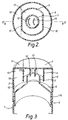
- Fig. 2 is a cross-sectional view taken along line I - I of Fig. 1.
- Fig. 3 is a view similar to Fig.1 but seen in cut-away perspective.
- a package for dispensing premeasured quantities of a granular or powdered fluent material comprises an elongate container 1 and an overcap 2, both of generally circular cross-section.
- the container 1 which is formed as an integral molded article, comprises a neck 3 having an opening 4 therein which, in this embodiment, is also of a circular cross-section.
- the neck terminates at its lowermost end in sloping shoulder portion 5 having a generally frusto-conical cross-section.
- the container is also provided with an inwardly-offset circumferential threaded portion 6 at the base of sloping shoulder portion 5 and which is adapted to engage with a corresponding threaded portion on the overcap as described below.
- the overcap 2 itself comprises ceiling 7, outer circumferential skirt 8, inner skirt 9, dispensing orifice 10, closure cover 11, and baffles 12 and 13.
- Outer skirt 8 and inner skirt 9 both extend generally downwardly from ceiling 7, outer skirt 8 terminating in a threaded portion 14 which is adapted to engage with the corresponding threaded portion 6 of container 1.
- overcap 2 can be snap-engaged with container 1 by means of projections and associated recesses on the overcap and container.
- Dispensing orifice 10 is a segmentally-shaped opening located within ceiling 7 in the region bounded by the lines of intersection of ceiling 7 with inner skirt 9 and outer skirt 8 and is covered by hinged closure cover 11.
- the transverse plane marked in Fig. 2 by the line II-II through the centres of container 1 and of dispensing orifice 10 is referred to herein as the "normal plane of tilt".
- Inner skirt 9 extends downwardly from ceiling 7 for a length sufficient to overlap container neck 3.
- inner skirt 9 in this embodiment has a truncated circular cross-section, wherein the skirt comprises opposed truncated side portions 15 and 16 disposed either side of container neck 3 and in close proximity thereto, the orientation of inner skirt 9 being such that its major axis is transverse to the normal plane of tilt II-II.
- inner skirt 9 has a generally circular cross-section while container neck 3 has an elongate cross-section and is disposed centrally within the inner skirt with its major axis generally parallel to the plane of tilt.
- baffles 12 and 13 take the form of in-line vertical plates which project downwardly from ceiling 7 towards and just into container neck 3, each baffle being of generally arcuate cross-section and disposed symmetrically about the normal place of tilt II-II with its concave surface proximal dispensing orifice 10.
- Ceiling 7, outer skirt 8, inner skirt 9 and sloping shoulder portion 5 together co-operate to define preliminary measuring section 17 above and around container neck 3, main measuring section 18 and outlet passage 19 which communicates at its outlet end with dispensing orifice 10.
- closure cover 11 In use, closure cover 11 is opened and the package is tilted along the normal plane of tilt until it assumes a generally inverted attitude and is then restored to its normal upright position. Tilting of the package in this manner charges preliminary measuring section 17 with a volume of granular or powdered fluent material as determined by the size, shape and relative variation of inner skirt 9, container neck 3 and baffles 12 and 13.
- preliminary measuring section 17 When the package is restored to its upright position, the contents of preliminary measuring section 17 fall generally sideways to the plane of tilt and into main measuring section 18. If main measuring section 18 has already been charged by previous tilting and restoration of the package, the contents of main measuring section 18 are discharged through outlet passage 19 and dispensing orifice 10 at the same time as preliminary measuring section 17 is charged during tilting of the package. Otherwise, the package is inverted for a second time in order to discharge the contents of main measuring section 18 through the dispensing orifice.
- the package can be sealed by screwing overcap 2 onto container 1 until the top end of neck 3 comes into contact with an annular cone seal provided on the undersurface of ceiling 7, the pitch of cooperating thread portions 6 and 14 being such that overcap 2 is moved between open and closed positions with a single twist of the hand (in practise, a 2:1 ratio pitch being used).
- a dust seal is provided in the form of two interfering rings 21 and 22 disposed respectively on the peripheral outer surface of container 1 and the peripheral inner surface of outer skirt 8. Interfering rings 21 and 22 also act as a stop to prevent inadvertent removal of overcap 2 from container 1.
- the package of the invention provides significant advantages in terms of structural simplicity, ease of manufacturing, constant discharge volumes and ease of modification.
- the package can be of a simple two-piece construction and the discharge volume can be easily modified merely by altering the length of the container neck, a modification which represents a trivial on-line manufacturing change.
- the discharge volume can be modified by altering the transverse diameter or longitudinal length of the inner skirt.
- the granular or powdered product can be sold in a separate non-dispensing container and the overcap screwed or otherwise attached to the container by the customer in the home.
- the single construction and ease of use of the package makes it a simple task for the customer to transfer the overcap from one container to another when the previous container is exhausted.
- the package can be sold with a removable freshness seal secured to the outer end of the dispensing orifice, the overcap being removed by the customer in order to allow access to the seal.
- the overcap and container can be threadedly or otherwise engaged in order to allow separation of the overcap and container but otherwise the overcap is retained in a static, permenently open position during subsequent use of the package by the customer.
Landscapes
- Physics & Mathematics (AREA)
- Fluid Mechanics (AREA)
- General Physics & Mathematics (AREA)
- Closures For Containers (AREA)
- Packages (AREA)
- Devices For Use In Laboratory Experiments (AREA)
- Details Of Rigid Or Semi-Rigid Containers (AREA)
Abstract
Description
- The invention relates to a dispensing package and more particularly to a package for dispensing premeasured quantities of a granular or powdered fluent material such as a detergent, bleaching composition, denture cleansing composition, fertilizer etc.
- Various kinds of so-called "fixed volume" discharge devices have been previously described in the art - see for example US-A-4151934, US-A-4170318 which describe devices adapted for mounting on the neck of a container, and EP-A-0194407 which describes a measuring cup which, in use, is mounted inside an opening of container. However, the devices which are described in the art are structurally and operationally complex, expensive to produce, give variable discharge volume and are difficult to modify to meet differing discharge requirements.
- The present invention provides a simple but effective solution to these various problems.
- Accordingly, the present invention provides a package for dispensing premeasured quantities of a granular or powdered fluent material, the package comprising:
- a) an elongate container having sloping shoulders and an open, upstanding neck, the container being surmounted by
- b) an overcap having a ceiling, a dispensing orifice, an outer skirt, and an inner skirt separate from or partially contiguous with the outer skirt and which surrounds the container neck in overlapping, laterally-spaced relationship thereto,
- In preferred embodiments, the inner skirt is separate from the outer skirt and surrounds the container neck in overlapping, laterally-spaced relationship thereto, whereby the skirt and neck cooperate to form an annular constriction to flow of material from the preliminary measuring section during inversion of the dispensing package. Preferably, the inner skirt and container neck are parallel to one another and have a lateral separation such that the area of the transverse section between the skirt and neck is from about 10% to about 70%, preferably from about 25% to about 40% of the area of the transverse section bounded by the inner skirt. Embodiments in which the container neck has a contoured (eg conical or parabolic) shape are also envisaged herein, however, in which case the relative areas of skirt and neck refer to a transverse plane through the lowermost edge of the inner skirt. It is also desirable that the overlap between the inner skirt and container neck is from about 10% to about 90%, preferably from about 30% to about 60% of the longitudinal length of the inner overcap; and while the overcap and neck may partially contact one another (for example, in the region of the inner skirt or ceiling of the overcap), it is preferred that they do not touch over more than 50% of the circumferential length of the container neck.
- In preferred embodiments, the container neck has a generally symmetrical cross-section and is most preferably circular. A symmetrically elongate or oval cross-section is also envisaged in certain embodiments however. Suitably, the inner skirt has a generally circular, truncated circular or oval cross-section and is concentric with the container neck. However, embodiments in which the container neck is offset relative to the inner skirt are also envisaged herein. Also the dispensing orifice is normally itself in an offset position relative to the longitudinal axis of the container.
- In other non-illustrated embodiments, the inner skirt is partially contiguous with the outer skirt whereby the inner skirt forms a partition extending generally transverse the normal plane of tilt on at least that side of the container neck proximal the dispensing orifice or, if appropriate, on either side of the container neck.
- In these embodiments, it will be understood that the lateral separation of the container neck from the partition or partitions and from those portions of the inner skirt contiguous with the outer skirt, is such as to provide the annular constriction to flow of material from the preliminary measuring section during inversion of the dispensing package.
- From the viewpoint of achieving a more reliable (ie less variable) discharge-volume, the package of the invention is preferably arranged or includes means for deflecting the flow of material from the preliminary measuring section in a direction sideways to the normal plane of tilt of the package as the package is restored after inversion to its normal upright position. In this context, the "normal plane of the tilt" of the package is taken to be that plane transverse to the longitudinal axis of the container which passes through the centre of the dispensing orifice. If the dispensing orifice is not transversely offset, however, the normal plane of tilt may be defined by reference to indicia marked on the container or cap.
- In a preferred arrangement, the relative shape and disposition of the inner skirt and container neck are such as to constrict flow of the material from the preliminary measuring section in directions along the normal plane of tilt of the package when the package is restored after inversion to its normal upright position, whereby the material is deflected or encouraged to flow in directions sideways to the normal plane of tilt.
- The sideways deflection of material can be achieved in various ways. In a preferred execution, however, the inner skirt has a generally oval or truncated circular cross-section and is disposed with its major axis transverse the normal plane of tilt. In the case of a truncated circular cross-section, moreover, it is important that the skirt should have a truncated portion on at least that side of the container neck proximal the dispensing orifice. The positioning of the inner skirt relative to the container neck is then chosen so as restrict flow of material in directions along the normal plane of tilt but to allow flow of material in a sideways direction.
- Other suitable means for deflecting or encouraging the flow of material in a sideways direction include the provision of a downward inflection in the ceiling of the overcap or of one or more baffles which, in either instance, project downwardly towards or into the container neck and which act to constrict flow of material in a forward direction as the package is restored to its normal upright position.
- It is also preferred herein that the overcap is moveable relative to the container neck in order to seal the container when not in use or in order to adjust the effective volume of the preliminary measuring section.
- Other features and advantages of the invention will be apparent from the following description taken in conjunction with the accompanying drawings in which:
- Fig. 1 illustrates a preferred embodiment of the invention wherein the package is shown in a fragmentary vertical cross-sectional view.
- Fig. 2 is a cross-sectional view taken along line I - I of Fig. 1.
- Fig. 3 is a view similar to Fig.1 but seen in cut-away perspective.
- Referring to Figures 1 to 3, a preferred embodiment of the invention will now be described.
- A package for dispensing premeasured quantities of a granular or powdered fluent material according to this embodiment comprises an elongate container 1 and an
overcap 2, both of generally circular cross-section. The container 1 which is formed as an integral molded article, comprises aneck 3 having an opening 4 therein which, in this embodiment, is also of a circular cross-section. The neck terminates at its lowermost end in slopingshoulder portion 5 having a generally frusto-conical cross-section. - The container is also provided with an inwardly-offset circumferential threaded
portion 6 at the base of slopingshoulder portion 5 and which is adapted to engage with a corresponding threaded portion on the overcap as described below. - The
overcap 2 itself comprisesceiling 7, outercircumferential skirt 8, inner skirt 9, dispensingorifice 10,closure cover 11, andbaffles Outer skirt 8 and inner skirt 9 both extend generally downwardly fromceiling 7,outer skirt 8 terminating in a threadedportion 14 which is adapted to engage with the corresponding threadedportion 6 of container 1. - In other embodiments of the invention, however,
overcap 2 can be snap-engaged with container 1 by means of projections and associated recesses on the overcap and container. - Dispensing
orifice 10 is a segmentally-shaped opening located withinceiling 7 in the region bounded by the lines of intersection ofceiling 7 with inner skirt 9 andouter skirt 8 and is covered byhinged closure cover 11. The transverse plane marked in Fig. 2 by the line II-II through the centres of container 1 and of dispensingorifice 10 is referred to herein as the "normal plane of tilt". - Inner skirt 9 extends downwardly from
ceiling 7 for a length sufficient to overlapcontainer neck 3. As best seen in Fig. 2, inner skirt 9 in this embodiment has a truncated circular cross-section, wherein the skirt comprises opposedtruncated side portions container neck 3 and in close proximity thereto, the orientation of inner skirt 9 being such that its major axis is transverse to the normal plane of tilt II-II. In other non-illustrated embodiments however, inner skirt 9 has a generally circular cross-section whilecontainer neck 3 has an elongate cross-section and is disposed centrally within the inner skirt with its major axis generally parallel to the plane of tilt. Again, the shape and relative disposition of the skirt and neck are such as to restrict flow of material along the normal plane of tilt and to encourage flow in a sideways direction. Baffles 12 and 13 take the form of in-line vertical plates which project downwardly fromceiling 7 towards and just intocontainer neck 3, each baffle being of generally arcuate cross-section and disposed symmetrically about the normal place of tilt II-II with its concave surfaceproximal dispensing orifice 10. -
Ceiling 7,outer skirt 8, inner skirt 9 and slopingshoulder portion 5 together co-operate to definepreliminary measuring section 17 above and aroundcontainer neck 3,main measuring section 18 andoutlet passage 19 which communicates at its outlet end with dispensingorifice 10. - In use,
closure cover 11 is opened and the package is tilted along the normal plane of tilt until it assumes a generally inverted attitude and is then restored to its normal upright position. Tilting of the package in this manner chargespreliminary measuring section 17 with a volume of granular or powdered fluent material as determined by the size, shape and relative variation of inner skirt 9,container neck 3 andbaffles - When the package is restored to its upright position, the contents of
preliminary measuring section 17 fall generally sideways to the plane of tilt and intomain measuring section 18. Ifmain measuring section 18 has already been charged by previous tilting and restoration of the package, the contents ofmain measuring section 18 are discharged throughoutlet passage 19 and dispensingorifice 10 at the same time aspreliminary measuring section 17 is charged during tilting of the package. Otherwise, the package is inverted for a second time in order to discharge the contents ofmain measuring section 18 through the dispensing orifice. - During storage or when the package is not in use, the package can be sealed by screwing
overcap 2 onto container 1 until the top end ofneck 3 comes into contact with an annular cone seal provided on the undersurface ofceiling 7, the pitch of cooperatingthread portions overcap 2 is moved between open and closed positions with a single twist of the hand (in practise, a 2:1 ratio pitch being used). - Moreover, in order to prevent dusting of the contents of the overcap into the area of threaded
portions rings outer skirt 8. Interferingrings overcap 2 from container 1. - The package of the invention provides significant advantages in terms of structural simplicity, ease of manufacturing, constant discharge volumes and ease of modification. The package can be of a simple two-piece construction and the discharge volume can be easily modified merely by altering the length of the container neck, a modification which represents a trivial on-line manufacturing change. Alternatively, the discharge volume can be modified by altering the transverse diameter or longitudinal length of the inner skirt.
- In addition, the granular or powdered product can be sold in a separate non-dispensing container and the overcap screwed or otherwise attached to the container by the customer in the home. The single construction and ease of use of the package makes it a simple task for the customer to transfer the overcap from one container to another when the previous container is exhausted.
- Alternatively the package can be sold with a removable freshness seal secured to the outer end of the dispensing orifice, the overcap being removed by the customer in order to allow access to the seal. In these embodiments the overcap and container can be threadedly or otherwise engaged in order to allow separation of the overcap and container but otherwise the overcap is retained in a static, permenently open position during subsequent use of the package by the customer.
wherein the ceiling, outer and inner skirts, neck and sloping shoulders together cooperate to define a preliminary measuring section above the container neck bounded by the ceiling and the inner skirt, a main measuring section bounded by the sloping shoulders and the outer skirt, and an outlet passage located between the inner and outer skirts and communicating with the dispensing orifice, and wherein the lateral separation of the inner skirt and container neck is such as to constrict flow of material from the preliminary measuring section to the main measuring section during inversion of the package and to permit such flow on restoring the package to its normal upright position.
Claims (12)
- A package for dispensing premeasured quantities of a granular or powdered fluent material, the package comprising:a) an elongate container (1) having sloping shoulders (5) and an open, upstanding neck (3), the container being surmounted byb) an overcap (2) having a ceiling (7), a dispensing orifice (10), an outer skirt (8), and an inner skirt (9) separate from or partially contiguous with the outer skirt and which surrounds the container neck in overlapping, laterally-spaced relationship thereto,wherein the ceiling (7), outer and inner skirts (8,9), neck (3) and sloping shoulders (5) together cooperate to define a preliminary measuring section (17) above the container neck (3) bounded by the ceiling (7) and the inner skirt (9), a main measuring section (18) bounded by the sloping shoulders (5) and the outer skirt (8), and an outlet passage (19) located between the inner (9) and outer (8) skirts and communicating with the dispensing orifice (10), and wherein the lateral separation of the inner skirt (9) and container neck (3) is such as to constrict flow of material from the preliminary measuring section (17) to the main measuring section (18) during inversion of the package and to permit such flow on restoring the package to its normal upright position.
- A package according to Claim 1 wherein the inner skirt (9) is separate from the outer skirt (8) and surrounds the container neck in overlapping, laterally-spaced relationship thereto, whereby said inner skirt (9) and neck (3) cooperate to form an annular constriction to flow of material from the preliminary measuring section during inversion of the dispensing package.
- A package according to Claim 2 wherein the inner skirt (9) and container neck (3) are parallel to one another and wherein the inner skirt and container neck have a lateral separation such that the area of the transverse section between the skirt and neck is from about 10% to about 70%, preferably from about 25% to about 40% of the area of the transverse section bounded by the inner skirt.
- A package according to any of Claims 1 to 3 wherein the container neck (3) has a generally symmetrical cross-section, preferably circular.
- A package according to Claim 4 wherein the inner skirt (9) has a generally circular, truncated circular or oval cross-section and is concentric with the container neck (3).
- A package according to Claim 1 wherein the inner skirt (9) is partially contiguous with the outer skirt (8) whereby the inner skirt (9) forms a partition extending generally transverse the normal plane of tilt on at least that side of the container neck (3) proximal the dispensing orifice (10).
- A package according to Claim 6 wherein the inner skirt (9) forms a partition extending generally transverse the normal plane of tilt on either side of the container neck (3).
- A package according to Claim 1 arranged or including means (12, 13) for deflecting the flow of material from the preliminary measuring section (17) in a direction sideways to the normal plane of tilt of the package as the package is restored after inversion to its normal upright position.
- A package according to Claim 8 wherein the relative shape and disposition of the inner skirt (9) and container neck (3) are such as to constrict flow of the material from the preliminary measuring section (17) in directions along the normal plane of tilt of the package as the package is restored after inversion to its normal upright position, whereby the material is deflected or encouraged to flow in directions sideways to the normal plane of tilt.
- A package according to Claim 9 wherein the inner skirt (9) has a generally oval or truncated circular cross-section and is disposed with its major axis transverse the normal plane of tilt and wherein in the case of a truncated circular cross-section, the skirt has a truncated portion (15, 16) on at least that side of the container neck proximal the dispensing orifice.
- A package according to any of Claims 8 to 10 wherein the deflecting means comprises a downward inflection of the ceiling or one or more baffles (12, 13) which project downwardly towards or into the container neck (3).
- A package according to any of Claims 1 to 11 wherein the overcap (2) is moveable relative to the container neck (3) in order to seal the container when not in use or in order to adjust the effective volume of the preliminary measuring section.
Priority Applications (1)
| Application Number | Priority Date | Filing Date | Title |
|---|---|---|---|
| AT90307775T ATE101712T1 (en) | 1989-07-26 | 1990-07-17 | DISPENSING CONTAINER. |
Applications Claiming Priority (2)
| Application Number | Priority Date | Filing Date | Title |
|---|---|---|---|
| GB8917070 | 1989-07-26 | ||
| GB898917070A GB8917070D0 (en) | 1989-07-26 | 1989-07-26 | Dispensing package |
Publications (2)
| Publication Number | Publication Date |
|---|---|
| EP0410620A1 EP0410620A1 (en) | 1991-01-30 |
| EP0410620B1 true EP0410620B1 (en) | 1994-02-16 |
Family
ID=10660645
Family Applications (1)
| Application Number | Title | Priority Date | Filing Date |
|---|---|---|---|
| EP90307775A Expired - Lifetime EP0410620B1 (en) | 1989-07-26 | 1990-07-17 | Dispensing package |
Country Status (11)
| Country | Link |
|---|---|
| US (1) | US5064106A (en) |
| EP (1) | EP0410620B1 (en) |
| JP (1) | JPH03226465A (en) |
| AT (1) | ATE101712T1 (en) |
| AU (1) | AU649227B2 (en) |
| CA (1) | CA2021436C (en) |
| DE (2) | DE9004716U1 (en) |
| DK (1) | DK0410620T3 (en) |
| ES (1) | ES2049423T3 (en) |
| GB (1) | GB8917070D0 (en) |
| NZ (1) | NZ234645A (en) |
Families Citing this family (24)
| Publication number | Priority date | Publication date | Assignee | Title |
|---|---|---|---|---|
| IT1258105B (en) * | 1992-02-14 | 1996-02-20 | Taplast Srl | DUST DISPENSER |
| US5547109A (en) * | 1992-11-19 | 1996-08-20 | Robbins, Iii; Edward S. | Container and measuring/dispensing cap assembly |
| US5465871A (en) * | 1992-11-19 | 1995-11-14 | Robbins, Iii; Edward S. | Spice jar and associated dispenser cap |
| US5542579A (en) * | 1992-11-19 | 1996-08-06 | Robbins, Iii; Edward S. | Dispensing cap with internal measuring chamber and selectively useable sifter |
| US5509579A (en) * | 1992-11-19 | 1996-04-23 | Robbins, Iii; Edward S. | No drip dispensing cap |
| US5632417A (en) * | 1992-11-19 | 1997-05-27 | Edward S. Robbins, III | Dispensing cap and related hinge |
| US5487494A (en) * | 1992-11-19 | 1996-01-30 | Robbins, Iii; Edward S. | Dispensing cap with internal measuring chamber and selectively useable sifter |
| US5411186A (en) * | 1992-11-19 | 1995-05-02 | Robbins, Iii; Edward S. | Dispensing cap with rotatable top |
| US5850944A (en) * | 1992-11-19 | 1998-12-22 | Edward S. Robbins, III | Measuring cap with pivoting dispenser |
| US5791528A (en) * | 1993-09-08 | 1998-08-11 | Edward S. Robbins, III | Clear plastic measuring/dispensing spout for a box-like container |
| US5346105A (en) * | 1993-12-30 | 1994-09-13 | Dart Industries Inc. | Dispenser for granular material |
| US5467903A (en) * | 1994-04-20 | 1995-11-21 | Ncm International, Inc. | Apparatus for dispensing measured amounts of granular product |
| SE9500056D0 (en) * | 1995-01-09 | 1995-01-09 | Broden Bengt Inge | Containers for medical preparations |
| USD379148S (en) * | 1995-08-08 | 1997-05-13 | Edward S. Robbins, III | Dispensing cap |
| USD378273S (en) * | 1995-08-08 | 1997-03-04 | Edward S. Robbins, III | Dispensing cap |
| US5671875A (en) * | 1996-07-02 | 1997-09-30 | Edward S. Robbins, III | Measuring/dispensing closure flip-top cap and built in shut-off blade |
| USD379434S (en) * | 1996-04-10 | 1997-05-27 | Edward S. Robbins, III | Dispensing cap |
| US5711463A (en) * | 1996-10-07 | 1998-01-27 | Chen; Han-Kuei | Distributor for distributing a small amount of particles |
| US5873493A (en) * | 1997-02-13 | 1999-02-23 | Rexam Plastics Inc. | Integrally molded measurer/dispenser |
| US5894965A (en) * | 1997-07-29 | 1999-04-20 | Edward S. Robbins, III | Measuring dispensing cap with spring biased flip top |
| JP2003026213A (en) * | 2001-07-19 | 2003-01-29 | Kyoei Seicha Kk | Fixed amount shake-out device |
| JP2006117262A (en) * | 2004-10-20 | 2006-05-11 | Daiwa Can Co Ltd | Fixed amount discharging cap |
| JP2006151461A (en) * | 2004-11-30 | 2006-06-15 | Yoshino Kogyosho Co Ltd | Fixed quantity discharging container |
| USD827436S1 (en) | 2015-08-04 | 2018-09-04 | Berlin Packaging, Llc | Lid |
Family Cites Families (11)
| Publication number | Priority date | Publication date | Assignee | Title |
|---|---|---|---|---|
| NL275520A (en) * | ||||
| US1957326A (en) * | 1933-03-28 | 1934-05-01 | Howard S Browne | Dispensing device |
| FR774149A (en) * | 1934-06-05 | 1934-11-30 | Improvements to dosers | |
| US2752076A (en) * | 1952-11-29 | 1956-06-26 | Locker Maurice | Apparatus for delivering measured volumetric quantities of granular, pulverulent and like fluent solid materials |
| US3023937A (en) * | 1957-03-12 | 1962-03-06 | Gustave O Matter | Measuring dispenser |
| NL6702149A (en) * | 1967-01-10 | 1968-07-11 | ||
| DE2557694C2 (en) * | 1975-12-20 | 1982-11-11 | Richard 7340 Geislingen Kohn | Dosing cap for grit dispenser |
| JPS5319883A (en) * | 1976-08-06 | 1978-02-23 | Noriyoshi Saeki | Container for blowing liquid in predetermined amount |
| DE2735372A1 (en) * | 1976-08-06 | 1978-02-09 | Noriyoshi Saeki | FIXED VOLUME DISPENSER |
| US4151934A (en) * | 1976-11-02 | 1979-05-01 | Noriyoshi Saeki | Fixed volume discharge device |
| JPS61117153U (en) * | 1985-01-09 | 1986-07-24 |
-
1989
- 1989-07-26 GB GB898917070A patent/GB8917070D0/en active Pending
-
1990
- 1990-04-26 DE DE9004716U patent/DE9004716U1/en not_active Expired - Lifetime
- 1990-07-17 DK DK90307775.8T patent/DK0410620T3/en active
- 1990-07-17 DE DE69006656T patent/DE69006656T2/en not_active Expired - Fee Related
- 1990-07-17 AT AT90307775T patent/ATE101712T1/en not_active IP Right Cessation
- 1990-07-17 ES ES90307775T patent/ES2049423T3/en not_active Expired - Lifetime
- 1990-07-17 EP EP90307775A patent/EP0410620B1/en not_active Expired - Lifetime
- 1990-07-18 CA CA002021436A patent/CA2021436C/en not_active Expired - Fee Related
- 1990-07-20 US US07/556,609 patent/US5064106A/en not_active Expired - Fee Related
- 1990-07-25 NZ NZ234645A patent/NZ234645A/en unknown
- 1990-07-25 AU AU59862/90A patent/AU649227B2/en not_active Ceased
- 1990-07-26 JP JP2198966A patent/JPH03226465A/en active Pending
Also Published As
| Publication number | Publication date |
|---|---|
| NZ234645A (en) | 1993-05-26 |
| ES2049423T3 (en) | 1994-04-16 |
| CA2021436A1 (en) | 1991-01-27 |
| EP0410620A1 (en) | 1991-01-30 |
| GB8917070D0 (en) | 1989-09-13 |
| DK0410620T3 (en) | 1994-05-24 |
| DE69006656D1 (en) | 1994-03-24 |
| DE69006656T2 (en) | 1994-08-11 |
| US5064106A (en) | 1991-11-12 |
| AU649227B2 (en) | 1994-05-19 |
| DE9004716U1 (en) | 1990-07-12 |
| AU5986290A (en) | 1991-01-31 |
| ATE101712T1 (en) | 1994-03-15 |
| CA2021436C (en) | 1996-01-09 |
| JPH03226465A (en) | 1991-10-07 |
Similar Documents
| Publication | Publication Date | Title |
|---|---|---|
| EP0410620B1 (en) | Dispensing package | |
| US5542585A (en) | Dispensing closure with pivotably mounted spout and means for limiting travel thereof | |
| US5465871A (en) | Spice jar and associated dispenser cap | |
| US4993606A (en) | Dispensing closure | |
| CA1137926A (en) | One-piece dispensing closure | |
| US5850953A (en) | Drip-free dispensing structure with collecting reservoir | |
| US6050434A (en) | Container closure with double-axis resiliently-biasing web-hinge structure | |
| US5251793A (en) | Dispensing closure | |
| WO1996024533A1 (en) | Dispensing closure with a modified lid for increased opening angle | |
| WO1994025359A1 (en) | Self-contained package for housing, dispensing and diluting concentrated liquid | |
| JPH0620909B2 (en) | Dispensing lid for containers with spout | |
| US5011048A (en) | Liquid dispensing measuring cap | |
| EP2499057A1 (en) | Dispensing cap, container and method for dispensing contents | |
| US3342383A (en) | Dispenser for granular materials | |
| EP0654417A1 (en) | Refillable package | |
| US2834519A (en) | Dispenser cap | |
| US4022464A (en) | Dispensing container and closure | |
| US20050025557A1 (en) | Packaging and dispensing device | |
| US4850501A (en) | Dispensing container | |
| US6095374A (en) | Closure for supporting a container of viscous liquid | |
| CA1241299A (en) | Liquid product dispensing package with self draining feature employing drip concentrator | |
| EP0485666A1 (en) | Container with multiple dispensing orifices and combination closure | |
| EP0404856B1 (en) | Dispensing closure | |
| JP4036505B2 (en) | Fixed discharge cap | |
| EP0775085A1 (en) | Dispenser cap for containers |
Legal Events
| Date | Code | Title | Description |
|---|---|---|---|
| PUAI | Public reference made under article 153(3) epc to a published international application that has entered the european phase |
Free format text: ORIGINAL CODE: 0009012 |
|
| AK | Designated contracting states |
Kind code of ref document: A1 Designated state(s): AT BE CH DE DK ES FR GB GR IT LI LU NL SE |
|
| 17P | Request for examination filed |
Effective date: 19910703 |
|
| 17Q | First examination report despatched |
Effective date: 19930211 |
|
| GRAA | (expected) grant |
Free format text: ORIGINAL CODE: 0009210 |
|
| AK | Designated contracting states |
Kind code of ref document: B1 Designated state(s): AT BE CH DE DK ES FR GB GR IT LI LU NL SE |
|
| REF | Corresponds to: |
Ref document number: 101712 Country of ref document: AT Date of ref document: 19940315 Kind code of ref document: T |
|
| REF | Corresponds to: |
Ref document number: 69006656 Country of ref document: DE Date of ref document: 19940324 |
|
| ET | Fr: translation filed | ||
| REG | Reference to a national code |
Ref country code: ES Ref legal event code: FG2A Ref document number: 2049423 Country of ref document: ES Kind code of ref document: T3 |
|
| ITF | It: translation for a ep patent filed | ||
| REG | Reference to a national code |
Ref country code: DK Ref legal event code: T3 |
|
| REG | Reference to a national code |
Ref country code: GR Ref legal event code: FG4A Free format text: 3011645 |
|
| EPTA | Lu: last paid annual fee | ||
| PLBE | No opposition filed within time limit |
Free format text: ORIGINAL CODE: 0009261 |
|
| STAA | Information on the status of an ep patent application or granted ep patent |
Free format text: STATUS: NO OPPOSITION FILED WITHIN TIME LIMIT |
|
| EAL | Se: european patent in force in sweden |
Ref document number: 90307775.8 |
|
| 26N | No opposition filed | ||
| PGFP | Annual fee paid to national office [announced via postgrant information from national office to epo] |
Ref country code: DK Payment date: 19980615 Year of fee payment: 9 |
|
| PGFP | Annual fee paid to national office [announced via postgrant information from national office to epo] |
Ref country code: AT Payment date: 19980619 Year of fee payment: 9 |
|
| PGFP | Annual fee paid to national office [announced via postgrant information from national office to epo] |
Ref country code: NL Payment date: 19980623 Year of fee payment: 9 Ref country code: GB Payment date: 19980623 Year of fee payment: 9 |
|
| PGFP | Annual fee paid to national office [announced via postgrant information from national office to epo] |
Ref country code: SE Payment date: 19980707 Year of fee payment: 9 Ref country code: FR Payment date: 19980707 Year of fee payment: 9 |
|
| PGFP | Annual fee paid to national office [announced via postgrant information from national office to epo] |
Ref country code: ES Payment date: 19980721 Year of fee payment: 9 |
|
| PGFP | Annual fee paid to national office [announced via postgrant information from national office to epo] |
Ref country code: LU Payment date: 19980724 Year of fee payment: 9 |
|
| PGFP | Annual fee paid to national office [announced via postgrant information from national office to epo] |
Ref country code: DE Payment date: 19980728 Year of fee payment: 9 |
|
| PGFP | Annual fee paid to national office [announced via postgrant information from national office to epo] |
Ref country code: GR Payment date: 19980731 Year of fee payment: 9 |
|
| PGFP | Annual fee paid to national office [announced via postgrant information from national office to epo] |
Ref country code: BE Payment date: 19980813 Year of fee payment: 9 |
|
| PGFP | Annual fee paid to national office [announced via postgrant information from national office to epo] |
Ref country code: CH Payment date: 19981013 Year of fee payment: 9 |
|
| PG25 | Lapsed in a contracting state [announced via postgrant information from national office to epo] |
Ref country code: LU Free format text: LAPSE BECAUSE OF NON-PAYMENT OF DUE FEES Effective date: 19990717 Ref country code: GB Free format text: LAPSE BECAUSE OF NON-PAYMENT OF DUE FEES Effective date: 19990717 Ref country code: AT Free format text: LAPSE BECAUSE OF NON-PAYMENT OF DUE FEES Effective date: 19990717 |
|
| PG25 | Lapsed in a contracting state [announced via postgrant information from national office to epo] |
Ref country code: SE Free format text: THE PATENT HAS BEEN ANNULLED BY A DECISION OF A NATIONAL AUTHORITY Effective date: 19990718 Ref country code: ES Free format text: LAPSE BECAUSE OF NON-PAYMENT OF DUE FEES Effective date: 19990718 |
|
| PG25 | Lapsed in a contracting state [announced via postgrant information from national office to epo] |
Ref country code: LI Free format text: LAPSE BECAUSE OF NON-PAYMENT OF DUE FEES Effective date: 19990731 Ref country code: GR Free format text: LAPSE BECAUSE OF NON-PAYMENT OF DUE FEES Effective date: 19990731 Ref country code: FR Free format text: THE PATENT HAS BEEN ANNULLED BY A DECISION OF A NATIONAL AUTHORITY Effective date: 19990731 Ref country code: CH Free format text: LAPSE BECAUSE OF NON-PAYMENT OF DUE FEES Effective date: 19990731 Ref country code: BE Free format text: LAPSE BECAUSE OF NON-PAYMENT OF DUE FEES Effective date: 19990731 |
|
| PG25 | Lapsed in a contracting state [announced via postgrant information from national office to epo] |
Ref country code: DK Free format text: LAPSE BECAUSE OF NON-PAYMENT OF DUE FEES Effective date: 19990802 |
|
| BERE | Be: lapsed |
Owner name: THE PROCTER & GAMBLE CY Effective date: 19990731 |
|
| PG25 | Lapsed in a contracting state [announced via postgrant information from national office to epo] |
Ref country code: NL Free format text: LAPSE BECAUSE OF NON-PAYMENT OF DUE FEES Effective date: 20000201 |
|
| GBPC | Gb: european patent ceased through non-payment of renewal fee |
Effective date: 19990717 |
|
| REG | Reference to a national code |
Ref country code: CH Ref legal event code: PL |
|
| REG | Reference to a national code |
Ref country code: DK Ref legal event code: EBP |
|
| EUG | Se: european patent has lapsed |
Ref document number: 90307775.8 |
|
| NLV4 | Nl: lapsed or anulled due to non-payment of the annual fee |
Effective date: 20000201 |
|
| PG25 | Lapsed in a contracting state [announced via postgrant information from national office to epo] |
Ref country code: DE Free format text: LAPSE BECAUSE OF NON-PAYMENT OF DUE FEES Effective date: 20000503 |
|
| REG | Reference to a national code |
Ref country code: FR Ref legal event code: ST |
|
| REG | Reference to a national code |
Ref country code: ES Ref legal event code: FD2A Effective date: 20000810 |
|
| PG25 | Lapsed in a contracting state [announced via postgrant information from national office to epo] |
Ref country code: IT Free format text: LAPSE BECAUSE OF NON-PAYMENT OF DUE FEES;WARNING: LAPSES OF ITALIAN PATENTS WITH EFFECTIVE DATE BEFORE 2007 MAY HAVE OCCURRED AT ANY TIME BEFORE 2007. THE CORRECT EFFECTIVE DATE MAY BE DIFFERENT FROM THE ONE RECORDED. Effective date: 20050717 |