EP0404856B1 - Dispensing closure - Google Patents
Dispensing closure Download PDFInfo
- Publication number
- EP0404856B1 EP0404856B1 EP89908019A EP89908019A EP0404856B1 EP 0404856 B1 EP0404856 B1 EP 0404856B1 EP 89908019 A EP89908019 A EP 89908019A EP 89908019 A EP89908019 A EP 89908019A EP 0404856 B1 EP0404856 B1 EP 0404856B1
- Authority
- EP
- European Patent Office
- Prior art keywords
- lid
- closure
- dispensing closure
- recess
- dispensing
- Prior art date
- Legal status (The legal status is an assumption and is not a legal conclusion. Google has not performed a legal analysis and makes no representation as to the accuracy of the status listed.)
- Expired - Lifetime
Links
Images

Classifications
-
- B—PERFORMING OPERATIONS; TRANSPORTING
- B65—CONVEYING; PACKING; STORING; HANDLING THIN OR FILAMENTARY MATERIAL
- B65D—CONTAINERS FOR STORAGE OR TRANSPORT OF ARTICLES OR MATERIALS, e.g. BAGS, BARRELS, BOTTLES, BOXES, CANS, CARTONS, CRATES, DRUMS, JARS, TANKS, HOPPERS, FORWARDING CONTAINERS; ACCESSORIES, CLOSURES, OR FITTINGS THEREFOR; PACKAGING ELEMENTS; PACKAGES
- B65D47/00—Closures with filling and discharging, or with discharging, devices
- B65D47/04—Closures with discharging devices other than pumps
- B65D47/06—Closures with discharging devices other than pumps with pouring spouts or tubes; with discharge nozzles or passages
- B65D47/08—Closures with discharging devices other than pumps with pouring spouts or tubes; with discharge nozzles or passages having articulated or hinged closures
- B65D47/0857—Closures with discharging devices other than pumps with pouring spouts or tubes; with discharge nozzles or passages having articulated or hinged closures made separately from the base element provided with the spout or discharge passage
- B65D47/0876—Hinges without elastic bias
- B65D47/089—Hinges without elastic bias located within a flat surface of the base element
- B65D47/0895—Hinges without elastic bias located within a flat surface of the base element one part of the hinge being integral with the hinged closure and the other part with the base element, without any other additional hinge element
-
- B—PERFORMING OPERATIONS; TRANSPORTING
- B65—CONVEYING; PACKING; STORING; HANDLING THIN OR FILAMENTARY MATERIAL
- B65D—CONTAINERS FOR STORAGE OR TRANSPORT OF ARTICLES OR MATERIALS, e.g. BAGS, BARRELS, BOTTLES, BOXES, CANS, CARTONS, CRATES, DRUMS, JARS, TANKS, HOPPERS, FORWARDING CONTAINERS; ACCESSORIES, CLOSURES, OR FITTINGS THEREFOR; PACKAGING ELEMENTS; PACKAGES
- B65D47/00—Closures with filling and discharging, or with discharging, devices
- B65D47/04—Closures with discharging devices other than pumps
- B65D47/06—Closures with discharging devices other than pumps with pouring spouts or tubes; with discharge nozzles or passages
- B65D47/08—Closures with discharging devices other than pumps with pouring spouts or tubes; with discharge nozzles or passages having articulated or hinged closures
- B65D47/0857—Closures with discharging devices other than pumps with pouring spouts or tubes; with discharge nozzles or passages having articulated or hinged closures made separately from the base element provided with the spout or discharge passage
- B65D47/0876—Hinges without elastic bias
- B65D47/088—Hinges without elastic bias located at an edge of the base element
- B65D47/0885—Hinges without elastic bias located at an edge of the base element one part of the hinge being integral with the hinged closure and the other part with the base element, without any other additional hinge element
-
- B—PERFORMING OPERATIONS; TRANSPORTING
- B65—CONVEYING; PACKING; STORING; HANDLING THIN OR FILAMENTARY MATERIAL
- B65D—CONTAINERS FOR STORAGE OR TRANSPORT OF ARTICLES OR MATERIALS, e.g. BAGS, BARRELS, BOTTLES, BOXES, CANS, CARTONS, CRATES, DRUMS, JARS, TANKS, HOPPERS, FORWARDING CONTAINERS; ACCESSORIES, CLOSURES, OR FITTINGS THEREFOR; PACKAGING ELEMENTS; PACKAGES
- B65D2251/00—Details relating to container closures
- B65D2251/10—Details of hinged closures
- B65D2251/1008—Means for locking the closure in open position
Definitions
- the present invention relates generally to a dispensing closure for containers and more particularly to a two piece dispensing closure, wherein a hinged lid is moved from a base of the closure to uncover an orifice through which the container contents are dispensed.
- This type of closure is made from moulded plastics and used extensively in dispensing food products, such as salad dressings, and for personal care and household products.
- the typical dispensing closure for a container comprises a generally circular base with a dispensing orifice in the front section of the upper surface and an annular skirt depending downwardly from the upper surface that is adapted to engage and secure the base to the container, usually by means of internal threads that are screwed onto the neck of the container.
- a lid having a plug on its underside for sealing the dispensing orifice is adapted to be pivotally moved with respect to the base to be opened and closed by the pressure of the finger or thumb.
- the base and lid of the closure are moulded as a single unit, the lid being connected to the base by a flexible hinge, which is known in the industry as a "living hinge".
- a flexible hinge which is known in the industry as a "living hinge”.
- a disadvantage of the "living hinge” is that the hinge portion of the closure has a tendency to crack, and eventually break, separating the lid from the base. Also, when the lid is rotated from the open position, it reaches a point from which it tends to snap rapidly to the closed position, and can splash liquid product, or even catapult one or more drops towards the user's face or clothing, thus presenting some danger if the product is an irritant.
- the hinge necessarily extends beyond the circumferential periphery of the closure of the rear of the base and creates problems during the assembly line filling of the container in that such an eccentric shape is subject to bumping and breakage, and can interfere with the highly automated equipment used during assembly of the closure and container of the product to be marketed.
- the "living hinge" design has been replaced to some extent by a dispensing closure design where the base has a notch located at the approximate centre of the top, and a relatively narrow rectangular channel extends from the notch to the front edge of the base with a dispensing orifice positioned in the channel proximate the front edge.
- a lid having a generally flat upper surface which terminates in a downwardly depending flange and indented end pieces is adapted to be received in a snap-fit into the notch, and when rotated to the closed position lies entirely within the channel.
- the underside of the lid has an annular plug which mates with and seals the orifice.
- the lid is maintained in the open position by means of an interference fit between the bottom edge of the flange and lugs located at the forward edge of the bottom of the notch where it intersects the rear of the channel.
- the lid is maintained in the notch in the open position by contact between a groove in the leading edge of the flange and a tab protruding upwardly from the intersection of the front wall and bottom of the notch.
- the base and a dispensing nozzle, or spout comprise two separate components that are interconnected through a modified ball and socket joint, or protruding pin or post from one component mating with a corresponding recess in the other component to form a pin/recess hinge structure between the two components.
- the outer surface of the base of the closure has a notch formed therein, said notch being shaped to receive one end of a hollow dispensing type nozzle of the lid which has a passageway for the liquid product. In the fully open position the nozzle communicates with the inside of the container by means of an orifice through the base located in the bottom of the notch.
- the nozzle end portion mates in a modified ball and socket configuration when press fit into the notch in the base.
- This latter ball and socket hinge design further relies upon a key-slot configuration in the notch of the base and the portion of the dispensing nozzle to be disposed within the notch, respectively, to limit the open position of the dispensing nozzle type lid, as well as interfering projections on the forward face of the notch and on the portion of the nozzle disposed within the notch to maintain the nozzle in an open position during the dispensing of product from the container.
- the interference fit yields to finger pressure to move the nozzle through the interference fit and return the lid to a closed position on the base of the closure.
- the lid is circular and the end of the lid opposite the orifice contains two slots which mate with two posts extending upwardly from the surface of the base of the circular closure at its periphery.
- the posts are flexible and exposed, and are therefore subject to damage during handling of the closure or container.
- the lid is insecurely held in place, is subject to twisting and lateral movement, and is easily pulled from the posts when the lid is in the open position.
- closure of this invention is an improvement over these prior art closures.
- a further object to the present invention is the provision of a two-piece dispensing closure which is simple in construction, pleasing in appearance and capable of a long, useful service life.
- Another object of the invention is to provide a dispensing closure with a lid that remains in a stable working position without cracking or separating from the base.
- the invention comprises a two-piece dispensing closure according to claim 1.
- the closure can be moulded from any of a variety of resilient polymeric materials well known to those in the art, including polypropylene, polyethylene and polyvinylchloride and copolymers and blends of said polymers.
- the two piece dispensing closure of the present invention is generally indicated by reference numeral 10 and comprises a base which is generally indicated by the reference numeral 12 and a lid which is generally indicated by the reference numeral 14.
- the base 12 includes a circular cover portion 16 which has a top surface 18 and an annular skirt, or side wall, 20 which is provided with internal threads 22 to enable the cap to be threaded onto the threaded neck of a container.
- the cover portion 16 of the base 12 has a dispensing orifice 24 having an upstanding annular rim 26.
- the cover portion 16 has an elevated rear land section 28 extending upwardly on the side of the cover portion 16 opposite the dispensing orifice 24.
- the land portion 28 has a substantially rectangular pivot recess 30.
- the pivot recess 30 is defined by a pair of vertical side walls 32, each wall 32 having a circular indent 34, a rear wall 31, and an outwardly sloping front wall 35 forming a portion of a ridge 36.
- the height of the ridge 36 is slightly less than the height of the elevated rear section 28 in order to accommodate the thickness of the lid, as described in detail below, to provide a uniformly flat upper surface to the closure when the lid is in the closed position.
- the lid 14 has a top portion 15 and a skirt portion 42 that is best shown in Figs. 5 & 6.
- the skirt portion closes down on the periphery of the base 12 when the lid 14 is in the closed position.
- the lid 14 is further provided with an annular plug 38 which extends downwardly from the bottom surface of the lid so that it mates with and seals the orifice 24 when the lid is in the closed position as shown in FIG. 4.
- the end of plug 38 is preferably provided with a bead, or flange, 39 that provides a secure interference fit with the narrowed throat 25 as the bead is pressed into orifice 24.
- pivot post 40 is dimensioned so as to be securely received in recess 30, and terminates in an end portion which has side surfaces 44, each surface having a spherical, or rounded, projection 46 which complements and is snapped into the indents 34 in each of the side walls of the recess 30.
- the combination of projections 46 and indents 34 forms a hinge connection between the lid 14 and the base 12, and can be reversed so that one or both of the indents are on the pivot post of the lid. This configuration enables the lid 14 to be pivoted from a closed position as shown in FIG. 4, in which the lid is flush with the top surface 18a of the rear land 28 and the orifice 24 is sealed by the plug 38, to an open position shown in FIG.
- the lid is at least 90° from the position shown in FIG. 4.
- the top surfaces of the lid 14, including the pivot post 40, and the elevated section 28, all lie in the same horizontal plane.
- the configuration also provides the means for securely holding the lid in the base.
- the skirt of the lid When the lid is in the closed position, the skirt of the lid continues the line of the side wall of the elevated rear section, or land, to give the appearance of a continuous vertical wall to the closure.
- the longitudinal and vertical continuity of the closure thus provides an aesthetically pleasing appearance, and to some degree provides a child-resistant safety feature in that the means of gaining entry to the container contents is not immediately apparent.
- the defined structure has the appearance of a one piece cylindrical cap.
- a dispensing orifice having an annular rim of substantial height may be used. It is desirable to have the rim defining the pour orifice of substantial height to permit cleaner dispensing that is less prone to dripping.
- the hinge elements of the closure are well protected within the confines of the recess 30, and the underside of the base is planar.
- An important aspect of the structure of the closure of the invention resides in the hinge interconnection of the lid 14 and the base 12 at recess 30. It is desirable that the rear wall 31 of the recess 30 is substantially flat so as to provide a surface against which the upper surface of the pivot post 40 may abut in the open position.
- This abutment together with the stable frictional interfit of the projections and indents of the hinge, provides a rigid mounting that is substantially aided in retaining its lateral stability due to inability of the side walls of the recess to move away from the mating side walls of the pivot post.
- This interfit stability is far superior to the relatively unstable interfit between the posts and lid of the prior art in which the open lid can easily be separated from the base.
- the lower terminus of pivot post 40 is generally circular in cross section, with a tangential surface intersecting the upper surface of the pivot at essentially a right angle along edge 43.
- edge 43 of the pivot post 40 contacts the rear wall 31 in an interference fit and then again freely rotates to the fully open position. This interference fit prevents the open lid from closing unless a slight finger pressure is applied. This feature is most desirable when dispensing products from the container with an accompanying shaking motion, which would otherwise tend to move the lid to a closed position.
- the rear wall 31 is inclined from the vertical towards the rear of the base to permit the lid to be opened more than 90° from the closed position.
- the extent of the incline of the rear wall 31 can be from a few degrees up to 45°, depending upon the geometry of the recess, the relative position of the pivot post in the recess, and the maximum angle desired between the lid and the upper surface of the base.
- the rear wall 31 makes an angle of at least 90° with the base, and most preferably an angle of from 100° to 120° with the base.
- FIG. 6B illustrates another modification of the pivot post in which the rear edge 41 of the lid is rounded, so that there is no interference fit with the rear wall 31 as the lid is raised and lowered.
- the lid is maintained in the open position by virtue of the frictional fit of the ends of the pivot post in the recess.
- the configurations of the recess and pivot post can be modified in various ways to produce the functionally equivalent relationship with the base of the closure.
- the pivot post can take the configuration which more nearly resembles a conventional ball joint with the recess likewise modified to the shape of a socket adapted to receive the ball.
- Other configurations known in the art can be adapted to configure the downwardly depending extension 40 from the rear of the generally circular front section 15 of the lid 14 to mate with the pivot recess 30 in a hinge relationship which has a centre of rotation located within the recess.
- the axis of rotation of the lid is along a chord, or line, which is perpendicular to the diameter passing through the centre of the dispensing orifice. Further, the axis of the recess is displaced on the opposite side of a diameter drawn between the recess and the dispensing orifice. In a preferred embodiment, the length of the recess along the axis of rotation is approximately one-third to one-half the diameter of the closure and it is located at a distance of approximately two-thirds to three-quarters of the diameter from the front skirt or wall of the closure nearest the dispensing orifice.
- the configuration of the abutting wall is not critical, and as shown in FIG. 6A, is inclined from the vertical towards the rear, which provides an aesthetically pleasing appearance and facilitates removal of the base from the mould.
- the base skirt 20 is provided with knurling to facilitate removal, and the upper surfaces of the base and lid can be embossed during moulding with decorative designs, the brand name of the product and instructions for use.
- closure is illustrated with internal threads, other means such as bayonet lugs and channels, or a snap-fit bead and recess, can be employed to secure the closure to the container.
- the configuration of the closure with the elevated rear land with the pivot recess disposed therein permits an inner safety seal to be installed on the container in contact with the underside of the base.
- the circular foil and polyethylene seal is placed inside the closure base, which is then screwed onto the container and then treated ultrasonically to melt and fuse the seal to the upper rim of the container.
- the hinge structure extends beneath the underside of the cover portion, the placement of an inner seal on the container is foreclosed.
- disposing the hinge structure of the closure out of contact with the container contents avoids potential product contamination.
- the front of the annular skirt 20 is provided with a recess 48 at the juncture of the base skirt 20 and the upper surface 16.
- the downwardly extending lid skirt 42 overhangs the annular side wall 20 above the recess 48, as shown in FIG. 4, to facilitate raising of the lid 14 by the user's finger or fingernail.
Abstract
Description
- The present invention relates generally to a dispensing closure for containers and more particularly to a two piece dispensing closure, wherein a hinged lid is moved from a base of the closure to uncover an orifice through which the container contents are dispensed. This type of closure is made from moulded plastics and used extensively in dispensing food products, such as salad dressings, and for personal care and household products.
- The typical dispensing closure for a container comprises a generally circular base with a dispensing orifice in the front section of the upper surface and an annular skirt depending downwardly from the upper surface that is adapted to engage and secure the base to the container, usually by means of internal threads that are screwed onto the neck of the container. A lid having a plug on its underside for sealing the dispensing orifice is adapted to be pivotally moved with respect to the base to be opened and closed by the pressure of the finger or thumb.
- In many instances the base and lid of the closure are moulded as a single unit, the lid being connected to the base by a flexible hinge, which is known in the industry as a "living hinge". A disadvantage of the "living hinge" is that the hinge portion of the closure has a tendency to crack, and eventually break, separating the lid from the base. Also, when the lid is rotated from the open position, it reaches a point from which it tends to snap rapidly to the closed position, and can splash liquid product, or even catapult one or more drops towards the user's face or clothing, thus presenting some danger if the product is an irritant.
- Moreover, in the "living hinge" design, at least a portion of the hinge necessarily extends beyond the circumferential periphery of the closure of the rear of the base and creates problems during the assembly line filling of the container in that such an eccentric shape is subject to bumping and breakage, and can interfere with the highly automated equipment used during assembly of the closure and container of the product to be marketed.
- The "living hinge" design has been replaced to some extent by a dispensing closure design where the base has a notch located at the approximate centre of the top, and a relatively narrow rectangular channel extends from the notch to the front edge of the base with a dispensing orifice positioned in the channel proximate the front edge. A lid having a generally flat upper surface which terminates in a downwardly depending flange and indented end pieces is adapted to be received in a snap-fit into the notch, and when rotated to the closed position lies entirely within the channel. The underside of the lid has an annular plug which mates with and seals the orifice. The lid is maintained in the open position by means of an interference fit between the bottom edge of the flange and lugs located at the forward edge of the bottom of the notch where it intersects the rear of the channel. The lid is maintained in the notch in the open position by contact between a groove in the leading edge of the flange and a tab protruding upwardly from the intersection of the front wall and bottom of the notch.
- Another type of dispensing closure has been developed where the base and a dispensing nozzle, or spout, comprise two separate components that are interconnected through a modified ball and socket joint, or protruding pin or post from one component mating with a corresponding recess in the other component to form a pin/recess hinge structure between the two components. In one form of the pin/recess hinge design, the outer surface of the base of the closure has a notch formed therein, said notch being shaped to receive one end of a hollow dispensing type nozzle of the lid which has a passageway for the liquid product. In the fully open position the nozzle communicates with the inside of the container by means of an orifice through the base located in the bottom of the notch. The nozzle end portion mates in a modified ball and socket configuration when press fit into the notch in the base. This latter ball and socket hinge design further relies upon a key-slot configuration in the notch of the base and the portion of the dispensing nozzle to be disposed within the notch, respectively, to limit the open position of the dispensing nozzle type lid, as well as interfering projections on the forward face of the notch and on the portion of the nozzle disposed within the notch to maintain the nozzle in an open position during the dispensing of product from the container. The interference fit yields to finger pressure to move the nozzle through the interference fit and return the lid to a closed position on the base of the closure.
- In another form of two piece dispensing closure, the lid is circular and the end of the lid opposite the orifice contains two slots which mate with two posts extending upwardly from the surface of the base of the circular closure at its periphery. In this slot and post design, the posts are flexible and exposed, and are therefore subject to damage during handling of the closure or container. In addition, the lid is insecurely held in place, is subject to twisting and lateral movement, and is easily pulled from the posts when the lid is in the open position.
- A further closure is described in WO-A-82/04028, which is illustrative of the preamble of claim 1.
- The closure of this invention is an improvement over these prior art closures.
- It is a principal object of the invention to provide a two-piece dispensing closure which has a hinge structure that provides a smooth peripheral symmetry, a planar top, and one which is less susceptible to damage than existing dispensing closures.
- A further object to the present invention is the provision of a two-piece dispensing closure which is simple in construction, pleasing in appearance and capable of a long, useful service life.
- It is another object of the invention to provide a container closure in which the lid will remain in the open position and resist closing even when the container is inverted and vigorously shaken.
- Another object of the invention is to provide a dispensing closure with a lid that remains in a stable working position without cracking or separating from the base.
- It is a preferred object of this invention to provide a closure in which there is an interference fit between the lid and the base as the lid is rotated to its fully open position, so that at least a perceptible finger pressure is required to move the lid to the closed position.
- It is also an object of this invention to provide a dispensing closure which will permit the contents of the container to be secured from tampering after filling and which will have a smooth underside free from crevices and openings which may become contaminated.
- In its broadest aspect the invention comprises a two-piece dispensing closure according to claim 1.
- The closure can be moulded from any of a variety of resilient polymeric materials well known to those in the art, including polypropylene, polyethylene and polyvinylchloride and copolymers and blends of said polymers.
- The invention will be best understood by reference to one of its structural forms, as illustrated by the accompanying drawings, in which:
- FIG. 1 is a front elevational view of a two piece dispensing closure embodying the features of the present invention;
- FIG. 2 is a left hand elevational view of the closure;
- FIG. 3 is a plan view of the closure, with cut-away sections;
- FIG. 4 is a vertical cross-sectional view of the closure taken along line IV-IV of FIG. 3, and looking in the direction of the arrows;
- FIG. 5 is a front elevational view of the closure with the lid in the open portion;
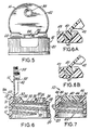
- FIG. 6 is a vertical cross-sectional view similar to FIG. 4, and showing the lid in the open position;
- FIG. 6A is an enlarged sectional view of the binge portion of the closure of FIG. 6;
- FIG. 6B is an enlarged sectional view similar to FIG. 6A, illustrating a different embodiment of the lid; and
- FIG. 7 is a vertical cross-sectional view of the closure taken along the line VII-VII of FIG. 3, and looking in the direction of the arrows.
- Referring to the drawings, the two piece dispensing closure of the present invention is generally indicated by
reference numeral 10 and comprises a base which is generally indicated by thereference numeral 12 and a lid which is generally indicated by thereference numeral 14. Thebase 12 includes acircular cover portion 16 which has atop surface 18 and an annular skirt, or side wall, 20 which is provided withinternal threads 22 to enable the cap to be threaded onto the threaded neck of a container. - Other means of affixing the closure to a container may be employed. Such means are well known to those skilled in the art. The
cover portion 16 of thebase 12 has a dispensingorifice 24 having an upstandingannular rim 26. - The
cover portion 16 has an elevatedrear land section 28 extending upwardly on the side of thecover portion 16 opposite the dispensingorifice 24. Theland portion 28 has a substantially rectangular pivot recess 30. Thepivot recess 30 is defined by a pair ofvertical side walls 32, eachwall 32 having acircular indent 34, arear wall 31, and an outwardly sloping front wall 35 forming a portion of aridge 36. The height of theridge 36 is slightly less than the height of the elevatedrear section 28 in order to accommodate the thickness of the lid, as described in detail below, to provide a uniformly flat upper surface to the closure when the lid is in the closed position. - The
lid 14 has atop portion 15 and askirt portion 42 that is best shown in Figs. 5 & 6. The skirt portion closes down on the periphery of thebase 12 when thelid 14 is in the closed position. Thelid 14 is further provided with anannular plug 38 which extends downwardly from the bottom surface of the lid so that it mates with and seals theorifice 24 when the lid is in the closed position as shown in FIG. 4. The end ofplug 38 is preferably provided with a bead, or flange, 39 that provides a secure interference fit with the narrowed throat 25 as the bead is pressed intoorifice 24. - At the opposite end of the lid,
pivot post 40 is dimensioned so as to be securely received inrecess 30, and terminates in an end portion which hasside surfaces 44, each surface having a spherical, or rounded,projection 46 which complements and is snapped into theindents 34 in each of the side walls of therecess 30. The combination ofprojections 46 andindents 34 forms a hinge connection between thelid 14 and thebase 12, and can be reversed so that one or both of the indents are on the pivot post of the lid. This configuration enables thelid 14 to be pivoted from a closed position as shown in FIG. 4, in which the lid is flush with thetop surface 18a of therear land 28 and theorifice 24 is sealed by theplug 38, to an open position shown in FIG. 6, in which the lid is at least 90° from the position shown in FIG. 4. When thelid 14 is in the closed position as shown in FIG. 4, the top surfaces of thelid 14, including thepivot post 40, and theelevated section 28, all lie in the same horizontal plane. In addition, the configuration also provides the means for securely holding the lid in the base. - When the lid is in the closed position, the skirt of the lid continues the line of the side wall of the elevated rear section, or land, to give the appearance of a continuous vertical wall to the closure. The longitudinal and vertical continuity of the closure thus provides an aesthetically pleasing appearance, and to some degree provides a child-resistant safety feature in that the means of gaining entry to the container contents is not immediately apparent. Moreover, the defined structure has the appearance of a one piece cylindrical cap. With the elevated rear section design of the closure and a lid covering a limited portion of the surface of the base, a dispensing orifice having an annular rim of substantial height may be used. It is desirable to have the rim defining the pour orifice of substantial height to permit cleaner dispensing that is less prone to dripping. Also, the hinge elements of the closure are well protected within the confines of the
recess 30, and the underside of the base is planar. - An important aspect of the structure of the closure of the invention resides in the hinge interconnection of the
lid 14 and the base 12 atrecess 30. It is desirable that therear wall 31 of therecess 30 is substantially flat so as to provide a surface against which the upper surface of thepivot post 40 may abut in the open position. This abutment, together with the stable frictional interfit of the projections and indents of the hinge, provides a rigid mounting that is substantially aided in retaining its lateral stability due to inability of the side walls of the recess to move away from the mating side walls of the pivot post. This interfit stability is far superior to the relatively unstable interfit between the posts and lid of the prior art in which the open lid can easily be separated from the base. - In a preferred embodiment of the invention mostly clearly shown in the detail of FIG. 6A, the lower terminus of
pivot post 40 is generally circular in cross section, with a tangential surface intersecting the upper surface of the pivot at essentially a right angle alongedge 43. As the lid is rotated from the closed position, edge 43 of the pivot post 40 contacts therear wall 31 in an interference fit and then again freely rotates to the fully open position. This interference fit prevents the open lid from closing unless a slight finger pressure is applied. This feature is most desirable when dispensing products from the container with an accompanying shaking motion, which would otherwise tend to move the lid to a closed position. If this occurred during dispensing so as to interfere with the flow of the product, the undesired consequences are obvious - the product would be likely to be directed to the user rather than the zone of desired impingement. This means for retaining the lid in the open position also eliminates the potential for splashing which can occur with the spring action "living hinge" of the prior one-piece closures which snap to a closed position. This interference fit is thus accomplished in general by employing on eccentric-concentric design for the rear wall of the recess and pivot post end. - Also as best illustrated in FIG. 6A, the
rear wall 31 is inclined from the vertical towards the rear of the base to permit the lid to be opened more than 90° from the closed position. As will be apparent to those skilled in the art the extent of the incline of therear wall 31 can be from a few degrees up to 45°, depending upon the geometry of the recess, the relative position of the pivot post in the recess, and the maximum angle desired between the lid and the upper surface of the base. In general, it is desirable from the standpoint of utility, as well as ease of moulding of the base part, that therear wall 31 makes an angle of at least 90° with the base, and most preferably an angle of from 100° to 120° with the base. - FIG. 6B illustrates another modification of the pivot post in which the
rear edge 41 of the lid is rounded, so that there is no interference fit with therear wall 31 as the lid is raised and lowered. In the configuration of FIG. 6B, the lid is maintained in the open position by virtue of the frictional fit of the ends of the pivot post in the recess. - As will also be appreciated by one skilled in the art the configurations of the recess and pivot post can be modified in various ways to produce the functionally equivalent relationship with the base of the closure. Thus, the pivot post can take the configuration which more nearly resembles a conventional ball joint with the recess likewise modified to the shape of a socket adapted to receive the ball. Other configurations known in the art can be adapted to configure the downwardly depending
extension 40 from the rear of the generallycircular front section 15 of thelid 14 to mate with thepivot recess 30 in a hinge relationship which has a centre of rotation located within the recess. - As will be apparent from the drawings, the axis of rotation of the lid is along a chord, or line, which is perpendicular to the diameter passing through the centre of the dispensing orifice. Further, the axis of the recess is displaced on the opposite side of a diameter drawn between the recess and the dispensing orifice. In a preferred embodiment, the length of the recess along the axis of rotation is approximately one-third to one-half the diameter of the closure and it is located at a distance of approximately two-thirds to three-quarters of the diameter from the front skirt or wall of the closure nearest the dispensing orifice.
- The configuration of the abutting wall is not critical, and as shown in FIG. 6A, is inclined from the vertical towards the rear, which provides an aesthetically pleasing appearance and facilitates removal of the base from the mould.
- In addition, the
base skirt 20 is provided with knurling to facilitate removal, and the upper surfaces of the base and lid can be embossed during moulding with decorative designs, the brand name of the product and instructions for use. - Although the closure is illustrated with internal threads, other means such as bayonet lugs and channels, or a snap-fit bead and recess, can be employed to secure the closure to the container.
- The configuration of the closure with the elevated rear land with the pivot recess disposed therein permits an inner safety seal to be installed on the container in contact with the underside of the base. Typically, the circular foil and polyethylene seal is placed inside the closure base, which is then screwed onto the container and then treated ultrasonically to melt and fuse the seal to the upper rim of the container. In closures wherein the hinge structure extends beneath the underside of the cover portion, the placement of an inner seal on the container is foreclosed. Moreover, disposing the hinge structure of the closure out of contact with the container contents avoids potential product contamination.
- Referring particularly to FIGS. 1 and 4, the front of the
annular skirt 20 is provided with arecess 48 at the juncture of thebase skirt 20 and theupper surface 16. The downwardly extendinglid skirt 42 overhangs theannular side wall 20 above therecess 48, as shown in FIG. 4, to facilitate raising of thelid 14 by the user's finger or fingernail.
Claims (39)
- A two-piece dispensing closure for a container, the closure comprising a generally circular base (12) including a cover portion (16), a skirt (20) depending downwardly from the cover portion, a dispensing orifice (24) in the cover portion (16); and a lid (14), said lid (14) having a plug (38) on its underside for sealing the dispensing orifice (24); characterised in that the cover portion (16) has a generally semi-circular forward top surface (18) in the front section of the base, and the dispensing orifice has a rim (26), wherein the top surface does not extend above the rim (26) of the dispensing orifice, and the top surface (18) extends to and is contiguous with an elevated rear land (28), the elevated rear land (28) being disposed above the top surface (18) and behind the dispensing orifice (24) and having a pivot recess (30) for pivotally receiving the lid (14), said pivot recess (30) being disposed to align the plug (38) with the dispensing orifice (24) and thereby allow mating of the plug and orifice when the lid is in the closed position.
- A dispensing closure as claimed in claim 1, characterised in that the dispensing orifice (24) extends above the upper surface (18).
- A dispensing closure as claimed in claim 1 or 2, characterised in that the lid (14) further comprises a rearwardly extending, downwardly depending pivot post (40) adapted frictionally to engage the pivot recess (30).
- A dispensing closure as claimed in claim 3, characterised in that the pivot recess (30) comprises two side surfaces (32) and a rear wall (31).
- A dispensing closure as claimed in any preceding claim, characterised in that said lid (14) has a substantially circular forward section (15).
- A dispensing closure as claimed in any preceding claim, characterised in that the elevated land (28) surrounds the pivot recess (30).
- A dispensing closure as claimed in claim 4, characterised in that the pivot recess (30) further comprises a front wall (35).
- A dispensing closure as claimed in claim 7, characterised in that the pivot post (40) has opposite vertical side surfaces (44) which engage the side surfaces (32) of said recess.
- A dispensing closure as claimed in claim 4, characterised in that the pivot post (40) has opposite vertical side surfaces (44) which engage the side surfaces (32) of said recess.
- A dispensing closure as claimed in claim 8, characterised in that the pivot post (40) and recess (30) are engaged by means of rounded projections (46), and each side wall (32) of the recess (30) has a complementary rounded indentation (34).
- A dispensing closure as claimed in any preceding claim, characterised in that the upper surface of the elevated land (28) is joined to the base (12) by an abutting wall (36).
- A dispensing closure as claimed in claim 11, characterised in that the abutting wall is continuous across the base (12).
- A dispensing closure as claimed in claim 10, characterised in that the upper surface of the elevated land (28) is joined to the base (12) by an abutting wall.
- A dispensing closure as claimed in claim 13, characterised in that the abutting wall is continuous across the base (12) and forms a front wall (35) of the pivot recess (30).
- A dispensing closure as claimed in claim 14, characterised in that the abutting wall lies on the opposite side of a diameter of the circular closure from the dispensing orifice (24).
- A dispensing closure as claimed in claim 15, characterised in that the closure has a front edge and the abutting wall is approximately three-quarters of the diameter from the front edge of the closure.
- A dispensing closure as claimed in claim 1, characterised in that the lid (14) further comprises a downwardly depending skirt (42) which extends from adjacent to the elevated land (28) when the lid (14) is closed and encloses an area under a front section of the closed lid (14).
- A dispensing closure as claimed in claim 17, characterised in that the annular side wall (20) of the closure has a recess (48) in its outer surface at the front section of the closure and the depending skirt (42) of the lid (14) overhangs the closure side wall above the recess.
- A dispensing closure as claimed in claim 2, characterised in that the lid (14) further comprises a downwardly depending skirt (42) which extends from adjacent to the elevated land (28) when the lid (14) is closed and encloses an area under a front section of the closed lid.
- A dispensing closure as claimed in any preceding claim, characterised in that the pivot recess (30) is centred about a diameter passing through the dispensing orifice (24).
- A dispensing closure as claimed in claim 11, characterised in that the pivot recess (30) is substantially rectilinear and the axis of rotation is parallel to the abutting wall (36).
- A dispensing closure as claimed in claim 21, characterised in that the length of the pivot recess (30) along the axis of rotation is from one-third to one-half of the diameter of the closure.
- A dispensing closure as claimed in any preceding claim, characterised in that the interior surfaces of the pivot recess (30) are substantially planar.
- A dispensing closure as claimed in claim 3 or 4, characterised in that the pivot post (40) extends below the bottom surface of the front section of the lid (14).
- A dispensing closure as claimed in claim 4, characterised in that the pivot recess (30) has side walls (32) adapted securely to engage the adjacent surfaces of the pivot post (40) in a frictional fit sufficient to maintain the lid (14) in an open position.
- A dispensing closure as claimed in claim 4, characterised in that the rear wall (31) of the pivot recess (30) is at an angle of from 90° to 135° to the upper surface (18) of the top portion of the base (12).
- A dispensing closure as claimed in claim 4, characterised in that the angle of the rear wall (31) is approximately 110°.
- A dispensing closure as claimed in claim 19, characterised in that the rear wall (31) of the pivot recess (30) is at an angle of from 90° to 135° to the upper surface (18) of the top portion of the base (12).
- A dispensing closure as claimed in claim 8, characterised in that the rear wall (31) of the pivot recess (30) is at an angle of at least 90° to the upper surface (18) of the base (12).
- A dispensing closure as claimed in claim 4, characterised in that the upper surface of the rearwardly extending portion of the pivot post (40) lies in the same plane as the forward section of the lid (14).
- A dispensing closure as claimed in claim 4, characterised in that the pivot post (40) includes a terminating edge (51) and there is an interference fit between the rear wall (31) of the recess (30) and the terminating edge (51) of the pivot post (40) as the lid (14) is rotated, thereby to restrain the movement of the lid (14) from the open to the closed position during use.
- A dispensing closure as claimed in claim 28, characterised in that the pivot post (40) includes a terminating edge (51) and there is an interference fit between the rear wall (31) of the recess (30) and the terminating edge (51) of the pivot post (40) as the lid (14) is rotated, thereby to restrain the movement of the lid (14) from the open to the closed position during use.
- A dispensing closure as claimed in claim 1, characterised in that the skirt (20) of the base (12) is annular and has a recess (48) in its outer surface at the front of the base (12) so that a depending skirt (42) of the lid (14) overhangs the base skirt (20) above the recess (48).
- A dispensing closure as claimed in claim 32, characterised in that the skirt (20) of the base (12) is annular and has a recess (48) in its outer surface at the front of the base (12) so that the depending skirt (42) of the lid (14) overhangs the base skirt (20) above the recess (48).
- A dispensing closure as claimed in claim 8, characterised in that the dispensing orifice (24) comprises an upwardly extending annular rim (26) which is engaged by the plug (38) of the lid in the closed position.
- A dispensing closure as claimed in claim 1, characterised in that the base (12) has an annular skirt (20) and the elevated land (28) extends upwardly from the annular skirt (20).
- A dispensing closure as claimed in claim 1, characterised in that the pivot recess (30) extends below the upper surface (18) of the base (12).
- A dispensing closure as claimed in claim 1, characterised in that the lid (14) follows the contour of the upper surface (18) of the base (12).
- A dispensing closure as claimed in any preceding claim, characterised in that the lid (14) is moulded from a resilient polymeric material.
Applications Claiming Priority (3)
| Application Number | Priority Date | Filing Date | Title |
|---|---|---|---|
| US21467688A | 1988-07-01 | 1988-07-01 | |
| US214676 | 1988-07-01 | ||
| PCT/US1989/002822 WO1990000140A1 (en) | 1988-07-01 | 1989-06-28 | Dispensing closure |
Publications (2)
| Publication Number | Publication Date |
|---|---|
| EP0404856A1 EP0404856A1 (en) | 1991-01-02 |
| EP0404856B1 true EP0404856B1 (en) | 1994-08-24 |
Family
ID=22800018
Family Applications (1)
| Application Number | Title | Priority Date | Filing Date |
|---|---|---|---|
| EP89908019A Expired - Lifetime EP0404856B1 (en) | 1988-07-01 | 1989-06-28 | Dispensing closure |
Country Status (17)
| Country | Link |
|---|---|
| EP (1) | EP0404856B1 (en) |
| JP (1) | JPH03500283A (en) |
| KR (1) | KR970002207B1 (en) |
| AR (1) | AR243467A1 (en) |
| AT (1) | ATE110336T1 (en) |
| AU (1) | AU632053B2 (en) |
| BR (1) | BR8907010A (en) |
| CA (1) | CA1312309C (en) |
| DE (1) | DE68917719T2 (en) |
| DK (1) | DK52590A (en) |
| FI (1) | FI93192C (en) |
| MX (1) | MX164660B (en) |
| NO (1) | NO900955D0 (en) |
| NZ (1) | NZ229782A (en) |
| PT (1) | PT91043B (en) |
| WO (1) | WO1990000140A1 (en) |
| ZA (1) | ZA895015B (en) |
Families Citing this family (2)
| Publication number | Priority date | Publication date | Assignee | Title |
|---|---|---|---|---|
| CH682143A5 (en) * | 1990-12-07 | 1993-07-30 | Soplar Sa | Plastic bottle produced by blowing process - comprises two indentations at top acting as link part for rotary pin of flap cover |
| FR2734241A1 (en) * | 1995-05-16 | 1996-11-22 | Shiseido International France | Container cover |
Family Cites Families (4)
| Publication number | Priority date | Publication date | Assignee | Title |
|---|---|---|---|---|
| US4441637A (en) * | 1981-05-15 | 1984-04-10 | Libit Sidney M | Dispensing type cap closure |
| US4399928A (en) * | 1982-04-14 | 1983-08-23 | Janler Corporation | Closure cap |
| US4460100A (en) * | 1983-06-17 | 1984-07-17 | Owens-Illinois, Inc. | Removable resistant container cap and neck assembly |
| NZ210919A (en) * | 1984-10-25 | 1988-02-12 | Sunbeam Plastics Corp | Two-piece dispensing closure for a container |
-
1989
- 1989-06-28 KR KR1019900700442A patent/KR970002207B1/en active IP Right Grant
- 1989-06-28 JP JP1507431A patent/JPH03500283A/en active Pending
- 1989-06-28 AT AT89908019T patent/ATE110336T1/en not_active IP Right Cessation
- 1989-06-28 EP EP89908019A patent/EP0404856B1/en not_active Expired - Lifetime
- 1989-06-28 BR BR898907010A patent/BR8907010A/en not_active IP Right Cessation
- 1989-06-28 DE DE68917719T patent/DE68917719T2/en not_active Expired - Fee Related
- 1989-06-28 WO PCT/US1989/002822 patent/WO1990000140A1/en active IP Right Grant
- 1989-06-28 AU AU38613/89A patent/AU632053B2/en not_active Ceased
- 1989-06-29 MX MX16652A patent/MX164660B/en unknown
- 1989-06-29 CA CA000604453A patent/CA1312309C/en not_active Expired - Fee Related
- 1989-06-30 PT PT91043A patent/PT91043B/en not_active IP Right Cessation
- 1989-06-30 NZ NZ229782A patent/NZ229782A/en unknown
- 1989-06-30 AR AR89314309A patent/AR243467A1/en active
- 1989-06-30 ZA ZA895015A patent/ZA895015B/en unknown
-
1990
- 1990-02-28 DK DK052590A patent/DK52590A/en not_active Application Discontinuation
- 1990-02-28 FI FI901019A patent/FI93192C/en not_active IP Right Cessation
- 1990-02-28 NO NO900955A patent/NO900955D0/en unknown
Also Published As
| Publication number | Publication date |
|---|---|
| DK52590D0 (en) | 1990-02-28 |
| FI93192B (en) | 1994-11-30 |
| FI901019A0 (en) | 1990-02-28 |
| NO900955L (en) | 1990-02-28 |
| PT91043B (en) | 1994-07-29 |
| DK52590A (en) | 1990-02-28 |
| AR243467A1 (en) | 1993-08-31 |
| NZ229782A (en) | 1992-06-25 |
| DE68917719D1 (en) | 1994-09-29 |
| KR900701618A (en) | 1990-12-03 |
| AU632053B2 (en) | 1992-12-17 |
| FI93192C (en) | 1995-03-10 |
| AU3861389A (en) | 1990-01-23 |
| ZA895015B (en) | 1990-04-25 |
| WO1990000140A1 (en) | 1990-01-11 |
| MX164660B (en) | 1992-09-11 |
| PT91043A (en) | 1990-02-08 |
| JPH03500283A (en) | 1991-01-24 |
| KR970002207B1 (en) | 1997-02-25 |
| CA1312309C (en) | 1993-01-05 |
| ATE110336T1 (en) | 1994-09-15 |
| BR8907010A (en) | 1990-12-26 |
| NO900955D0 (en) | 1990-02-28 |
| DE68917719T2 (en) | 1995-05-04 |
| EP0404856A1 (en) | 1991-01-02 |
Similar Documents
| Publication | Publication Date | Title |
|---|---|---|
| US4993606A (en) | Dispensing closure | |
| US5395015A (en) | Dispensing closure with a modified lid for increased opening angle | |
| US5251793A (en) | Dispensing closure | |
| US4727999A (en) | Safety dispensing closure-container package | |
| US4826026A (en) | Child resistant dispensing closure | |
| US5542585A (en) | Dispensing closure with pivotably mounted spout and means for limiting travel thereof | |
| US4666068A (en) | Two piece dispensing closure | |
| CA1089803A (en) | Container closure having hinged cover retained by safety latch | |
| US6739781B2 (en) | Scrubbing structure | |
| US4903870A (en) | Dispensing closure | |
| US6477743B1 (en) | Twist-openable dispensing closure accommodating optional liner puncture feature | |
| US7658295B2 (en) | Closure with deflectable finger for retention of lid hinge shaft | |
| EP0109704B1 (en) | Liquid product pouring and measuring package with self draining feature | |
| US4261486A (en) | One-piece dispensing closure with lid hold-open feature | |
| US5938087A (en) | Spurt minimizing dispensing structure | |
| US20080023502A1 (en) | Closure Cap | |
| GB2202215A (en) | Closure and container package | |
| AU2002320484A1 (en) | Twist Openable Dispensing Closure Accommodating Optional Liner Puncture Feature | |
| US4632266A (en) | Container cap | |
| US5022566A (en) | Press-open side dispensing closure | |
| EP0701523B1 (en) | Clog-resistant toggle disk closure | |
| EP1339617B1 (en) | Dispensing closure for a container | |
| EP0404856B1 (en) | Dispensing closure | |
| US4807781A (en) | Container and dispensing-closure assembly | |
| JP2521350Y2 (en) | cap |
Legal Events
| Date | Code | Title | Description |
|---|---|---|---|
| PUAI | Public reference made under article 153(3) epc to a published international application that has entered the european phase |
Free format text: ORIGINAL CODE: 0009012 |
|
| 17P | Request for examination filed |
Effective date: 19900319 |
|
| AK | Designated contracting states |
Kind code of ref document: A1 Designated state(s): AT BE CH DE FR GB IT LI LU NL SE |
|
| 17Q | First examination report despatched |
Effective date: 19911002 |
|
| GRAA | (expected) grant |
Free format text: ORIGINAL CODE: 0009210 |
|
| AK | Designated contracting states |
Kind code of ref document: B1 Designated state(s): AT BE CH DE FR GB IT LI LU NL SE |
|
| REF | Corresponds to: |
Ref document number: 110336 Country of ref document: AT Date of ref document: 19940915 Kind code of ref document: T |
|
| REF | Corresponds to: |
Ref document number: 68917719 Country of ref document: DE Date of ref document: 19940929 |
|
| ITF | It: translation for a ep patent filed |
Owner name: DE DOMINICIS & MAYER S.R.L. |
|
| ET | Fr: translation filed | ||
| EAL | Se: european patent in force in sweden |
Ref document number: 89908019.6 |
|
| PLBE | No opposition filed within time limit |
Free format text: ORIGINAL CODE: 0009261 |
|
| STAA | Information on the status of an ep patent application or granted ep patent |
Free format text: STATUS: NO OPPOSITION FILED WITHIN TIME LIMIT |
|
| 26N | No opposition filed | ||
| PGFP | Annual fee paid to national office [announced via postgrant information from national office to epo] |
Ref country code: FR Payment date: 19980320 Year of fee payment: 10 |
|
| PGFP | Annual fee paid to national office [announced via postgrant information from national office to epo] |
Ref country code: SE Payment date: 19980323 Year of fee payment: 10 |
|
| PGFP | Annual fee paid to national office [announced via postgrant information from national office to epo] |
Ref country code: NL Payment date: 19980326 Year of fee payment: 10 |
|
| PGFP | Annual fee paid to national office [announced via postgrant information from national office to epo] |
Ref country code: LU Payment date: 19980327 Year of fee payment: 10 |
|
| PGFP | Annual fee paid to national office [announced via postgrant information from national office to epo] |
Ref country code: AT Payment date: 19980406 Year of fee payment: 10 |
|
| PGFP | Annual fee paid to national office [announced via postgrant information from national office to epo] |
Ref country code: GB Payment date: 19980414 Year of fee payment: 10 |
|
| PGFP | Annual fee paid to national office [announced via postgrant information from national office to epo] |
Ref country code: CH Payment date: 19980422 Year of fee payment: 10 |
|
| PGFP | Annual fee paid to national office [announced via postgrant information from national office to epo] |
Ref country code: BE Payment date: 19980423 Year of fee payment: 10 |
|
| PGFP | Annual fee paid to national office [announced via postgrant information from national office to epo] |
Ref country code: DE Payment date: 19980630 Year of fee payment: 10 |
|
| PG25 | Lapsed in a contracting state [announced via postgrant information from national office to epo] |
Ref country code: LU Free format text: LAPSE BECAUSE OF NON-PAYMENT OF DUE FEES Effective date: 19990628 Ref country code: GB Free format text: LAPSE BECAUSE OF NON-PAYMENT OF DUE FEES Effective date: 19990628 Ref country code: AT Free format text: LAPSE BECAUSE OF NON-PAYMENT OF DUE FEES Effective date: 19990628 |
|
| PG25 | Lapsed in a contracting state [announced via postgrant information from national office to epo] |
Ref country code: SE Free format text: THE PATENT HAS BEEN ANNULLED BY A DECISION OF A NATIONAL AUTHORITY Effective date: 19990629 |
|
| PG25 | Lapsed in a contracting state [announced via postgrant information from national office to epo] |
Ref country code: LI Free format text: LAPSE BECAUSE OF NON-PAYMENT OF DUE FEES Effective date: 19990630 Ref country code: FR Free format text: THE PATENT HAS BEEN ANNULLED BY A DECISION OF A NATIONAL AUTHORITY Effective date: 19990630 Ref country code: CH Free format text: LAPSE BECAUSE OF NON-PAYMENT OF DUE FEES Effective date: 19990630 Ref country code: BE Free format text: LAPSE BECAUSE OF NON-PAYMENT OF DUE FEES Effective date: 19990630 |
|
| BERE | Be: lapsed |
Owner name: BOLEN THOMAS R. Effective date: 19990630 Owner name: BOLEN ROBERT J. JR. Effective date: 19990630 |
|
| PG25 | Lapsed in a contracting state [announced via postgrant information from national office to epo] |
Ref country code: NL Free format text: LAPSE BECAUSE OF NON-PAYMENT OF DUE FEES Effective date: 20000101 |
|
| REG | Reference to a national code |
Ref country code: CH Ref legal event code: PL |
|
| GBPC | Gb: european patent ceased through non-payment of renewal fee |
Effective date: 19990628 |
|
| EUG | Se: european patent has lapsed |
Ref document number: 89908019.6 |
|
| NLV4 | Nl: lapsed or anulled due to non-payment of the annual fee |
Effective date: 20000101 |
|
| PG25 | Lapsed in a contracting state [announced via postgrant information from national office to epo] |
Ref country code: DE Free format text: LAPSE BECAUSE OF NON-PAYMENT OF DUE FEES Effective date: 20000503 |
|
| REG | Reference to a national code |
Ref country code: FR Ref legal event code: ST |
|
| PG25 | Lapsed in a contracting state [announced via postgrant information from national office to epo] |
Ref country code: IT Free format text: LAPSE BECAUSE OF NON-PAYMENT OF DUE FEES;WARNING: LAPSES OF ITALIAN PATENTS WITH EFFECTIVE DATE BEFORE 2007 MAY HAVE OCCURRED AT ANY TIME BEFORE 2007. THE CORRECT EFFECTIVE DATE MAY BE DIFFERENT FROM THE ONE RECORDED. Effective date: 20050628 |