US5542579A - Dispensing cap with internal measuring chamber and selectively useable sifter - Google Patents
Dispensing cap with internal measuring chamber and selectively useable sifter Download PDFInfo
- Publication number
- US5542579A US5542579A US08/352,104 US35210494A US5542579A US 5542579 A US5542579 A US 5542579A US 35210494 A US35210494 A US 35210494A US 5542579 A US5542579 A US 5542579A
- Authority
- US
- United States
- Prior art keywords
- panel
- sifter
- cap
- weir
- lid
- Prior art date
- Legal status (The legal status is an assumption and is not a legal conclusion. Google has not performed a legal analysis and makes no representation as to the accuracy of the status listed.)
- Expired - Lifetime
Links
- 230000002093 peripheral effect Effects 0.000 claims abstract description 8
- 229920003023 plastic Polymers 0.000 claims description 7
- 239000000463 material Substances 0.000 claims description 6
- 239000012780 transparent material Substances 0.000 claims description 3
- 230000000903 blocking effect Effects 0.000 claims 1
- 238000010276 construction Methods 0.000 description 6
- 239000007787 solid Substances 0.000 description 4
- 230000002787 reinforcement Effects 0.000 description 3
- 230000000295 complement effect Effects 0.000 description 1
- 230000006835 compression Effects 0.000 description 1
- 238000007906 compression Methods 0.000 description 1
- 235000013305 food Nutrition 0.000 description 1
- 238000010348 incorporation Methods 0.000 description 1
- 230000003014 reinforcing effect Effects 0.000 description 1
- 235000021055 solid food Nutrition 0.000 description 1
- 235000013599 spices Nutrition 0.000 description 1
Images


Classifications
-
- B—PERFORMING OPERATIONS; TRANSPORTING
- B65—CONVEYING; PACKING; STORING; HANDLING THIN OR FILAMENTARY MATERIAL
- B65D—CONTAINERS FOR STORAGE OR TRANSPORT OF ARTICLES OR MATERIALS, e.g. BAGS, BARRELS, BOTTLES, BOXES, CANS, CARTONS, CRATES, DRUMS, JARS, TANKS, HOPPERS, FORWARDING CONTAINERS; ACCESSORIES, CLOSURES, OR FITTINGS THEREFOR; PACKAGING ELEMENTS; PACKAGES
- B65D47/00—Closures with filling and discharging, or with discharging, devices
- B65D47/04—Closures with discharging devices other than pumps
- B65D47/06—Closures with discharging devices other than pumps with pouring spouts or tubes; with discharge nozzles or passages
- B65D47/08—Closures with discharging devices other than pumps with pouring spouts or tubes; with discharge nozzles or passages having articulated or hinged closures
- B65D47/0804—Closures with discharging devices other than pumps with pouring spouts or tubes; with discharge nozzles or passages having articulated or hinged closures integrally formed with the base element provided with the spout or discharge passage
- B65D47/0833—Hinges without elastic bias
- B65D47/0847—Hinges without elastic bias located within a flat surface of the base element
-
- B—PERFORMING OPERATIONS; TRANSPORTING
- B65—CONVEYING; PACKING; STORING; HANDLING THIN OR FILAMENTARY MATERIAL
- B65D—CONTAINERS FOR STORAGE OR TRANSPORT OF ARTICLES OR MATERIALS, e.g. BAGS, BARRELS, BOTTLES, BOXES, CANS, CARTONS, CRATES, DRUMS, JARS, TANKS, HOPPERS, FORWARDING CONTAINERS; ACCESSORIES, CLOSURES, OR FITTINGS THEREFOR; PACKAGING ELEMENTS; PACKAGES
- B65D41/00—Caps, e.g. crown caps or crown seals, i.e. members having parts arranged for engagement with the external periphery of a neck or wall defining a pouring opening or discharge aperture; Protective cap-like covers for closure members, e.g. decorative covers of metal foil or paper
- B65D41/02—Caps or cap-like covers without lines of weakness, tearing strips, tags, or like opening or removal devices
- B65D41/26—Caps or cap-like covers serving as, or incorporating, drinking or measuring vessels
-
- B—PERFORMING OPERATIONS; TRANSPORTING
- B65—CONVEYING; PACKING; STORING; HANDLING THIN OR FILAMENTARY MATERIAL
- B65D—CONTAINERS FOR STORAGE OR TRANSPORT OF ARTICLES OR MATERIALS, e.g. BAGS, BARRELS, BOTTLES, BOXES, CANS, CARTONS, CRATES, DRUMS, JARS, TANKS, HOPPERS, FORWARDING CONTAINERS; ACCESSORIES, CLOSURES, OR FITTINGS THEREFOR; PACKAGING ELEMENTS; PACKAGES
- B65D47/00—Closures with filling and discharging, or with discharging, devices
- B65D47/04—Closures with discharging devices other than pumps
- B65D47/06—Closures with discharging devices other than pumps with pouring spouts or tubes; with discharge nozzles or passages
- B65D47/08—Closures with discharging devices other than pumps with pouring spouts or tubes; with discharge nozzles or passages having articulated or hinged closures
- B65D47/0804—Closures with discharging devices other than pumps with pouring spouts or tubes; with discharge nozzles or passages having articulated or hinged closures integrally formed with the base element provided with the spout or discharge passage
- B65D47/0809—Closures with discharging devices other than pumps with pouring spouts or tubes; with discharge nozzles or passages having articulated or hinged closures integrally formed with the base element provided with the spout or discharge passage and elastically biased towards both the open and the closed positions
- B65D47/0814—Closures with discharging devices other than pumps with pouring spouts or tubes; with discharge nozzles or passages having articulated or hinged closures integrally formed with the base element provided with the spout or discharge passage and elastically biased towards both the open and the closed positions by at least three hinge sections, at least one having a length different from the others
-
- B—PERFORMING OPERATIONS; TRANSPORTING
- B65—CONVEYING; PACKING; STORING; HANDLING THIN OR FILAMENTARY MATERIAL
- B65D—CONTAINERS FOR STORAGE OR TRANSPORT OF ARTICLES OR MATERIALS, e.g. BAGS, BARRELS, BOTTLES, BOXES, CANS, CARTONS, CRATES, DRUMS, JARS, TANKS, HOPPERS, FORWARDING CONTAINERS; ACCESSORIES, CLOSURES, OR FITTINGS THEREFOR; PACKAGING ELEMENTS; PACKAGES
- B65D47/00—Closures with filling and discharging, or with discharging, devices
- B65D47/04—Closures with discharging devices other than pumps
- B65D47/06—Closures with discharging devices other than pumps with pouring spouts or tubes; with discharge nozzles or passages
- B65D47/08—Closures with discharging devices other than pumps with pouring spouts or tubes; with discharge nozzles or passages having articulated or hinged closures
- B65D47/0857—Closures with discharging devices other than pumps with pouring spouts or tubes; with discharge nozzles or passages having articulated or hinged closures made separately from the base element provided with the spout or discharge passage
- B65D47/0866—Closures with discharging devices other than pumps with pouring spouts or tubes; with discharge nozzles or passages having articulated or hinged closures made separately from the base element provided with the spout or discharge passage and elastically biased towards the closed position only
-
- B—PERFORMING OPERATIONS; TRANSPORTING
- B65—CONVEYING; PACKING; STORING; HANDLING THIN OR FILAMENTARY MATERIAL
- B65D—CONTAINERS FOR STORAGE OR TRANSPORT OF ARTICLES OR MATERIALS, e.g. BAGS, BARRELS, BOTTLES, BOXES, CANS, CARTONS, CRATES, DRUMS, JARS, TANKS, HOPPERS, FORWARDING CONTAINERS; ACCESSORIES, CLOSURES, OR FITTINGS THEREFOR; PACKAGING ELEMENTS; PACKAGES
- B65D47/00—Closures with filling and discharging, or with discharging, devices
- B65D47/04—Closures with discharging devices other than pumps
- B65D47/20—Closures with discharging devices other than pumps comprising hand-operated members for controlling discharge
- B65D47/26—Closures with discharging devices other than pumps comprising hand-operated members for controlling discharge with slide valves, i.e. valves that open and close a passageway by sliding over a port, e.g. formed with slidable spouts
- B65D47/261—Closures with discharging devices other than pumps comprising hand-operated members for controlling discharge with slide valves, i.e. valves that open and close a passageway by sliding over a port, e.g. formed with slidable spouts having a rotational or helicoidal movement
-
- B—PERFORMING OPERATIONS; TRANSPORTING
- B65—CONVEYING; PACKING; STORING; HANDLING THIN OR FILAMENTARY MATERIAL
- B65D—CONTAINERS FOR STORAGE OR TRANSPORT OF ARTICLES OR MATERIALS, e.g. BAGS, BARRELS, BOTTLES, BOXES, CANS, CARTONS, CRATES, DRUMS, JARS, TANKS, HOPPERS, FORWARDING CONTAINERS; ACCESSORIES, CLOSURES, OR FITTINGS THEREFOR; PACKAGING ELEMENTS; PACKAGES
- B65D83/00—Containers or packages with special means for dispensing contents
- B65D83/06—Containers or packages with special means for dispensing contents for dispensing powdered or granular material
-
- G—PHYSICS
- G01—MEASURING; TESTING
- G01F—MEASURING VOLUME, VOLUME FLOW, MASS FLOW OR LIQUID LEVEL; METERING BY VOLUME
- G01F11/00—Apparatus requiring external operation adapted at each repeated and identical operation to measure and separate a predetermined volume of fluid or fluent solid material from a supply or container, without regard to weight, and to deliver it
- G01F11/10—Apparatus requiring external operation adapted at each repeated and identical operation to measure and separate a predetermined volume of fluid or fluent solid material from a supply or container, without regard to weight, and to deliver it with measuring chambers moved during operation
- G01F11/26—Apparatus requiring external operation adapted at each repeated and identical operation to measure and separate a predetermined volume of fluid or fluent solid material from a supply or container, without regard to weight, and to deliver it with measuring chambers moved during operation wherein the measuring chamber is filled and emptied by tilting or inverting the supply vessel, e.g. bottle-emptying apparatus
- G01F11/261—Apparatus requiring external operation adapted at each repeated and identical operation to measure and separate a predetermined volume of fluid or fluent solid material from a supply or container, without regard to weight, and to deliver it with measuring chambers moved during operation wherein the measuring chamber is filled and emptied by tilting or inverting the supply vessel, e.g. bottle-emptying apparatus for fluent solid material
-
- B—PERFORMING OPERATIONS; TRANSPORTING
- B65—CONVEYING; PACKING; STORING; HANDLING THIN OR FILAMENTARY MATERIAL
- B65D—CONTAINERS FOR STORAGE OR TRANSPORT OF ARTICLES OR MATERIALS, e.g. BAGS, BARRELS, BOTTLES, BOXES, CANS, CARTONS, CRATES, DRUMS, JARS, TANKS, HOPPERS, FORWARDING CONTAINERS; ACCESSORIES, CLOSURES, OR FITTINGS THEREFOR; PACKAGING ELEMENTS; PACKAGES
- B65D2543/00—Lids or covers essentially for box-like containers
- B65D2543/00009—Details of lids or covers for rigid or semi-rigid containers
- B65D2543/00018—Overall construction of the lid
- B65D2543/00055—Lids serving as, or incorporating, drinking or measuring vessels
Definitions
- the present invention relates generally to dispensing containers and, more specifically, to dispensing cap constructions enabling accurately measured amounts of the container contents (in granular, particulate or powdered form) to be dispensed from the cap.
- Dispensing containers are, of course, well known and are used in many different industries for many different purposes.
- One such use is in the food industry, and a specific example includes jars and other similar containers which contain solid foods (such as spices) in particulate, granular or powder-like form.
- solid foods such as spices
- a measuring spoon or separate measuring cup is utilized in conjunction with the jar or container when accurate amounts are to be obtained.
- the present invention eliminates the need for measuring spoons or cups by providing a hollow cap, which serves as its own measuring device, for use with an otherwise conventional container. While the incorporation of a measuring function into a container/cap construction for the discharge of desired amounts of the container contents is not new (see for example, U.S. Pat. Nos. 1,802,284; 2,804,103; 3,860,111; 4,613,057 and 4,635,828), the present invention provides improved and simplified structures for accomplishing this result, while generally retaining the desirable option of substantially unrestricted pouring and/or shaking of the container contents from the dispensing cap.
- the present invention provides a selectively useable sifter within the measuring cap construction.
- the sifter is incorporated as an integral and stationary part of the cap construction.
- a plastic cap which includes a top and a depending skirt.
- the skirt incorporates an inverted, partial dome-like (or partial upright bowl-shaped) sifter panel which is provided with a plurality of sifter apertures but which is also formed to create a flow opening lying on one side of a horizontal center line extending through the cap.
- This flow opening is defined by a straight edge or chord on the sifter panel extending between two parts of the annular periphery of the skirt, and is referred to herein sometimes as a chord-shaped opening.
- the sifter panel in combination with the skirt wall and the cap top wall, form a measuring chamber into which a desired amount of container contents may be transferred as described further herein.
- the cap top wall forms a fully openable cap lid hinged to the cap skirt.
- the free edge of the cap which is diametrically opposed to the integral hinge, lies on the opposite side of the horizontal cap center line from the flow opening.
- the cap lid (and optionally a portion of the depending skirt) is provided with volume gradations in the form of level lines and suitable alpha and/or numeric characters, enabling the user to precisely transfer measured amounts of contents from the container into the cap measuring chamber.
- a weir dam panel having a curvature complementary to that of the sifter panel, is snap-fit onto the stationary sifter panel at a location coincident with a vertical center axis of the cap, such that the weir dam panel is rotatable about the vertical center axis, relative to the stationary sifter panel.
- This weir dam panel is provided with a shape similar to the sifter panel in plan so that a chord-shaped flow opening established by a straight edge or chord of the weir dam panel may be aligned vertically with the similarly shaped flow opening in the sifter panel.
- a vertical tab is provided on the weir dam panel which extends upwardly to permit the user to rotate the weir dam panel to either of two operative positions.
- the cap as described herein can be used to dispense container contents in any of three dispensing modes.
- a first mode the user rotates the weir dam panel until the weir dam panel flow opening overlies the sitter panel flow opening so that, with the cap lid closed, the user can freely transfer measured amounts of container contents into the measuring chamber. Once a measured amount is transferred to the measuring chamber, the measured amount can be discharged simply by opening the cap lid.
- the cap lid may remain open so that the user can simply free flow unrestricted amounts of container contents through the cap. In this first weir dam panel position, the sifting apertures of the sifter panel are closed by the solid weir dam panel.
- the sifter apertures are opened by rotating the weir dam panel 180° to a second operative position, enabling the user to dispense container contents through the sifter apertures and through the open lid, using a typical back and forth shaking motion.
- this second operative position of the weir dam panel the relatively large flow opening in the sifter panel is closed by the solid portion of the weir dam panel.
- the dispensing cap is formed as a three-piece construction, i.e., (1) the depending skirt and the sifter panel are formed as a unit; (2) the weir dam panel; and (3) the cap lid.
- the cap lid may be formed integrally with the skirt and hinged by a thinned region (or "living hinge").
- All three of the components in accordance with the invention may be made of transparent plastic material to facilitate accurate transfer measured amounts of container contents from the container into the measuring chamber in the cap.
- the weir dam panel, sifter panel and skirt may be constructed of an opaque plastic material while the lid remains transparent to create an aesthetically pleasing contrast.
- volumetric indicators will be provided at least on the lid (and if desired on the cap skirt in the event the latter is made of transparent plastic) to enable the user to more accurately transfer measured amounts to the cap measuring chamber.
- the present invention relates to a measuring/dispensing cap adapted for attachment to an open upper end of a container, the cap comprising a lid and a peripheral skirt extending downwardly from the lid, the lid pivotally secured to the skirt; a sifter panel integral with said skirt and separating the skirt into upper and lower sections, the upper section including a measuring chamber and the lower section including means for attaching the cap to the open upper end of the container; and wherein at least the lid is provided with volume indicators; the sifter panel formed to provide a flow opening on one side of a horizontal centerline extending across the cap, the flow opening defined in part by a first edge extending parallel to and spaced from the horizontal centerline; and a rotatable weir dam panel overlying the sifter panel, the weir dam panel having a second edge which may be aligned with the first edge to enable substantially free flow of container contents through the flow opening.
- FIG. 1 is a perspective view of the combination dispensing cap sifter in accordance with this invention but with the cap lid removed for clarity;
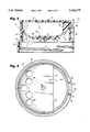
- FIG. 2 is a side section of the dispenser/sifter cap in accordance with the invention.
- FIG. 3 is a plan view of the dispensing/sifter cap in accordance with the invention but with the cap lid and weir dam panel removed for clarity;
- FIG. 4 is a plan view of the weir dam panel utilized in the dispensing/sifter cap of this invention.
- FIG. 5 is a plan view of the cap lid in accordance with the invention.
- FIG. 6 is an end elevation of the cap lid shown in FIG. 5;
- FIG. 7 is a partial side elevation view of the inside wall of a hinge mechanism joining the cap lid to the cap in accordance with the invention.
- FIG. 8 is a side section similar to FIG. 2 but illustrating a larger capacity cap.
- the measuring/dispensing cap 10 includes a cap lid 12 (not shown in FIG. 1) and a depending skirt portion 14.
- the depending skirt portion includes an annular shoulder 16 defining a lower skirt portion 18 having internal screw threads 20 adapted to cooperate with external threads on the upstanding dispensing portion of a container or jar (not shown) in the manner of a typical threaded closure. That portion of the skirt 14 extending upwardly from shoulder 16 will be referred to as the upper skirt portion 22.
- the interior of the cap 10 is formed with a partially annular integral sifter panel 24 which is curved in the manner shown in FIG. 2 (and considered to resemble an inverted dome or an upright bowl), and which includes a plurality of sifter apertures 26.
- the arcuate extent of the sifter panel terminates along a chord or straight edge 28 to thereby define a chord-shaped flow opening 30 defined by the edge 28 in combination with an arcuate portion of the upper peripheral skirt 22.
- This sifter panel 24 is formed with a centrally located aperture 32 which permits securement of a weir dam panel 34 as described below.
- Edge 28 lies to one side of a horizontal centerline through the cap (and perpendicular to the vertical center axis of the cap extending through aperture 32).
- the weir dam panel 34 has a size and arcuate shape similar to that of the sifter panel but does not include any apertures of the type shown at 26, i.e., the weir panel is solid.
- the weir dam panel has a curvature similar to the sifter panel and the arcuate extent of the weir dam panel as defined by edge 36 is also similar to the sifter panel in that the chord or straight edge 36 of the weir dam panel creates a second chord-shaped flow opening which may be aligned with the sifter panel flow opening 30 so that the flow similar sized and shaped openings of each are superposed one on the other.
- the weir dam panel 34 is also provided with a pair of downwardly projecting spring fingers 38 which, upon lateral compression, will pass through the aperture 32 in the sifter panel and then spring outwardly so that the weir dam panel 34 is rotatably mounted on the sifter panel 34 for rotation about the vertical center axis coincident with a vertical center axis of the cap.
- the weir dam panel 34 is also provided with an upstanding projection or tab 40 which facilitates user rotation of the weir dam panel within the cap.
- sifter panel 24 and weir dam panel 34 by reason of their inverted dome-like or bowl-shapes, create along with closed lid 12, a measuring chamber C within the cap 10 into which container contents may be transferred as described in greater detail below.
- the lid 12 is secured to the upper portion 22 of the depending skirt portion 14 by means of hinge 42 which is described below in greater detail in connection with FIGS. 2, 3, 5 and 7.
- the lid is provided with volumetric indicia, or level indicators I (which may include alpha and/or numeric characters) to assist the use in determining the amount of contents transferred to the measuring chamber C.
- the entire cap 10 may be constructed of transparent plastic. It will be appreciated, however, that the skirt portion 14 and/or panels 24 and 34 may be formed of opaque material if desired. In the event the skirt portion 14 is formed of transparent material, the indicia I may be continued onto the skirt.
- the hinge mechanism 42 is comprised of a pair of laterally spaced reinforcement ribs 44, 44' extending downwardly along the "rear" skirt wall and preferably integral therewith.
- a second component of the hinge 42 includes a tab 46 extending downwardly from the lid skirt or flange 49 in alignment above and between the reinforcing ribs 44, 44'.
- Tab 46 is formed with two lateral extending projections 48, 50 of generally spherical shape.
- the inside of reinforcement rib 44' (as well as rib 44) is formed with a generally spherical recess 52 and tapered entry groove 54, and the inside of reinforcement rib 44 is similarly formed.
- the lateral projections 48, 50 may be snap fit into the spherical recesses 52 in opposed inside surfaces of ribs 44 and 44' with the aid of tapered entry grooves 54 thereby forming a horizontal pivot axis extending between the lateral projections 48, 50.
- the tapered entry grooves 54 define limits of pivotal movement of the lid or door 12 between open and closed positions.
- other hinge arrangements such as a simple "living" or integral hinge may be employed.
- the cap 12 can be secured to a reinforced area of the cap skirt portion 14 by a thinned area which acts as a hinge.
- the lid 12 is also formed with a pair of lifting tabs 56, 58, best seen in FIG. 5, to facilitate opening of the lid.
- the user may rotate the weir dam panel 34 to a first operative position so as to cover the sifter apertures 26 in fixed panel 24, and so that the edges 28 and 36 are aligned thereby permitting container contents to flow freely through the flow opening 30.
- contents of the container may be transferred from the container into the measuring chamber C.
- both the sifter panel 24 and the weir dam panel 34 act as a dam to prevent additional undesired amounts of material from spilling over the aligned edges 28 and 36 and into the measuring chamber C.
- the lid 12 at this time is closed. Subsequently, the lid 12 may be opened via pivoting movement about the hinge 42 to thereby allow precisely measured amounts of container contents to be dispensed from the cap, sliding along the curved surface of the weir dam panel 34. Alternatively, with the panels in the positions described above, and if the lid 12 is open from the outset, contents may be discharged directly out of the cap via flow opening 30 without regard for amount. On the other hand, the user may rotate the weir panel to a second operative position so that the solid portion thereof blocks the opening 30 but leaves the sifter panel apertures 26 uncovered so that contents within the container may be sprinkled directly from the cap 10 through the open lid 12 without regard to the particular amount dispensed.
- both the sifter panel 24 and the weir dam panel 34 and depending skirt 14 may be altered to enlarge or reduce the size of the measuring chamber C.
- an enlarged cap 110 is illustrated, using reference numerals similar to those used in FIGS. 1-7, but with the prefix "1" added, to designate corresponding elements.
- the curvature of both the sifter panel 124 and weir dam panel 134 have been increased to provide a measuring chamber C' of greater volume.
- the construction of the cap 110 as well as the manner in which it may be utilized are otherwise similar to that described above in connection with the first embodiment.
Landscapes
- Engineering & Computer Science (AREA)
- Mechanical Engineering (AREA)
- Physics & Mathematics (AREA)
- Fluid Mechanics (AREA)
- General Physics & Mathematics (AREA)
- Closures For Containers (AREA)
Abstract
Description
Claims (15)
Priority Applications (5)
| Application Number | Priority Date | Filing Date | Title |
|---|---|---|---|
| US08/352,104 US5542579A (en) | 1992-11-19 | 1994-11-30 | Dispensing cap with internal measuring chamber and selectively useable sifter |
| US08/408,409 US5632417A (en) | 1992-11-19 | 1995-03-22 | Dispensing cap and related hinge |
| PCT/US1995/015459 WO1996016896A1 (en) | 1994-11-30 | 1995-11-29 | Dispensing cap with measuring chamber and sifter |
| AU45044/96A AU4504496A (en) | 1994-11-30 | 1995-11-29 | Dispensing cap with measuring chamber and sifter |
| CA002205843A CA2205843C (en) | 1994-11-30 | 1995-11-29 | Dispensing cap with measuring chamber and sifter |
Applications Claiming Priority (6)
| Application Number | Priority Date | Filing Date | Title |
|---|---|---|---|
| US97904292A | 1992-11-19 | 1992-11-19 | |
| US4708693A | 1993-04-16 | 1993-04-16 | |
| US08/220,530 US5487494A (en) | 1992-11-19 | 1994-03-31 | Dispensing cap with internal measuring chamber and selectively useable sifter |
| US08/237,336 US5465871A (en) | 1992-11-19 | 1994-05-03 | Spice jar and associated dispenser cap |
| US08/288,896 US5509582A (en) | 1992-11-19 | 1994-08-10 | Dispensing cap with internal measuring chamber |
| US08/352,104 US5542579A (en) | 1992-11-19 | 1994-11-30 | Dispensing cap with internal measuring chamber and selectively useable sifter |
Related Parent Applications (1)
| Application Number | Title | Priority Date | Filing Date |
|---|---|---|---|
| US08/220,530 Continuation-In-Part US5487494A (en) | 1992-11-19 | 1994-03-31 | Dispensing cap with internal measuring chamber and selectively useable sifter |
Related Child Applications (1)
| Application Number | Title | Priority Date | Filing Date |
|---|---|---|---|
| US08/408,409 Continuation-In-Part US5632417A (en) | 1992-11-19 | 1995-03-22 | Dispensing cap and related hinge |
Publications (1)
| Publication Number | Publication Date |
|---|---|
| US5542579A true US5542579A (en) | 1996-08-06 |
Family
ID=23383813
Family Applications (1)
| Application Number | Title | Priority Date | Filing Date |
|---|---|---|---|
| US08/352,104 Expired - Lifetime US5542579A (en) | 1992-11-19 | 1994-11-30 | Dispensing cap with internal measuring chamber and selectively useable sifter |
Country Status (4)
| Country | Link |
|---|---|
| US (1) | US5542579A (en) |
| AU (1) | AU4504496A (en) |
| CA (1) | CA2205843C (en) |
| WO (1) | WO1996016896A1 (en) |
Cited By (42)
| Publication number | Priority date | Publication date | Assignee | Title |
|---|---|---|---|---|
| US5676282A (en) * | 1996-10-04 | 1997-10-14 | Satterfield; Delbert | Volumetrically variable measuring dispenser |
| USD398234S (en) | 1996-09-16 | 1998-09-15 | Dart Industries Inc. | Sifter crown |
| US6321949B1 (en) * | 1998-06-13 | 2001-11-27 | Sheena Pittaway | Measure system |
| US6422426B1 (en) | 2001-03-28 | 2002-07-23 | Edward S. Robbins, III | Dispensing cap with internal measuring chamber |
| US20030057115A1 (en) * | 2001-07-26 | 2003-03-27 | Langeler Gerard E. | Pill delivery system |
| US6691901B2 (en) | 2001-12-14 | 2004-02-17 | Gateway Plastics, Inc. | Closure for a container |
| US6801032B2 (en) | 2000-07-11 | 2004-10-05 | Murata Manufacturing Co., Ltd. | Transport device for transporting parts to a transport medium |
| USD509426S1 (en) | 1997-10-28 | 2005-09-13 | Gateway Plastics, Inc. | Integrally-formed closure for a container |
| USD513452S1 (en) | 2002-09-27 | 2006-01-10 | Gateway Plastics, Inc. | Closure for a container |
| US20060045737A1 (en) * | 2004-08-31 | 2006-03-02 | Foxconn Technology Co., Ltd. | Fan holder |
| US7121438B2 (en) | 2004-09-17 | 2006-10-17 | Seaquist Closures Foreign, Inc. | Multiple lid closure with open lid retention feature |
| US7134575B2 (en) | 2002-12-21 | 2006-11-14 | Gateway Plastics, Inc. | Closure for a container |
| USD532298S1 (en) | 2004-11-20 | 2006-11-21 | Gateway Plastics, Inc. | Closure for a container |
| USD532691S1 (en) | 2004-11-20 | 2006-11-28 | Gateway Plastics, Inc. | Closure for a container |
| USD533452S1 (en) | 2004-11-20 | 2006-12-12 | Gateway Plastics, Inc. | Closure for a container |
| US20070228079A1 (en) * | 2006-02-16 | 2007-10-04 | Gateway Plastics, Inc. | Closure for a container |
| USD564143S1 (en) * | 2006-10-24 | 2008-03-11 | Reckitt Benckiser N.V. | Dispensing device |
| USD568555S1 (en) * | 2006-10-24 | 2008-05-06 | Reckitt Benckiser N.V. | Dispensing device |
| US7438204B2 (en) | 2005-10-13 | 2008-10-21 | S. C. Johnson & Son, Inc. | Apparatus for dispensing a granular product from a container |
| US20080257918A1 (en) * | 2004-09-05 | 2008-10-23 | Gateway Plastics Inc. | Closure for a Container |
| US20080277424A1 (en) * | 2007-05-10 | 2008-11-13 | Robert Larimer | Flip-top shaker |
| USD596029S1 (en) | 2006-06-20 | 2009-07-14 | Gateway Plastics, Inc. | Closure for a container |
| US20090193890A1 (en) * | 2008-02-01 | 2009-08-06 | Mentesh William M | Measuring Cap |
| US20100012145A1 (en) * | 2008-07-17 | 2010-01-21 | Loprete Wayne J | Sifter Dish Insert For Cosmetic Package |
| US20100147903A1 (en) * | 2008-12-12 | 2010-06-17 | Graham Packaging Company, L.P. | One piece unit dose liquid dispensing closure and packaging system |
| FR2945714A1 (en) * | 2009-05-20 | 2010-11-26 | Oreal | Cosmetic product e.g. powder, storing and distributing device, has cup comprising annular zone that connects another annular zone and open zone with each other and defines slope failure with respect to latter annular zone |
| USD679181S1 (en) | 2012-03-26 | 2013-04-02 | Gateway Plastics, Inc. | Closure for a container |
| US8899437B2 (en) | 2012-01-20 | 2014-12-02 | Gateway Plastics, Inc. | Closure with integrated dosage cup |
| US8955705B2 (en) | 2012-03-26 | 2015-02-17 | Gateway Plastics, Inc. | Closure for a container |
| US9247799B1 (en) | 2011-10-14 | 2016-02-02 | Wormser Corporation | Product dispenser with inertial valve |
| US9475623B2 (en) | 2012-03-26 | 2016-10-25 | Gateway Plastics, Inc. | Closure for a container |
| US9511924B1 (en) * | 2010-07-29 | 2016-12-06 | Robert J. Crawford | Container apparatus with single-pill dispensing and related method |
| US9656796B1 (en) * | 2014-03-17 | 2017-05-23 | Michael Carl Cammarata | Pill dispensing bottle system |
| US20180184783A1 (en) * | 2016-12-30 | 2018-07-05 | L'oreal, Paris, France | Systems and devices for cosmetic powder accumulation management |
| US20190218017A1 (en) * | 2016-09-19 | 2019-07-18 | Clariant Healthcare Packaging (France) Sas | Flow-limiting device and container for unitary products |
| US10457475B2 (en) | 2017-07-25 | 2019-10-29 | Phoenix Closures, Inc. | Cap assembly with dispensing vessel |
| US10569942B2 (en) | 2017-10-06 | 2020-02-25 | J.L. Clark, Inc. | Measured volume dispensing closure, closure having overlapping cover members, and methods |
| US20220127061A1 (en) * | 2019-07-11 | 2022-04-28 | Express Scripts Strategic Development, Inc. | Cap assembly for a medication container |
| WO2022221131A1 (en) * | 2021-04-13 | 2022-10-20 | Ams Llc | Measured fluid dispenser |
| US11768095B2 (en) | 2019-10-07 | 2023-09-26 | Ams, Llc | Measured fluid dispenser |
| US11827442B1 (en) | 2019-07-11 | 2023-11-28 | Express Scripts Strategic Development, Inc. | Cap assembly for a medication container |
| US12071286B1 (en) | 2019-07-11 | 2024-08-27 | Express Scripts Strategic Development, Inc. | Cap assembly for a medication container |
Families Citing this family (2)
| Publication number | Priority date | Publication date | Assignee | Title |
|---|---|---|---|---|
| EP1236652A1 (en) * | 2001-03-02 | 2002-09-04 | Crown Cork & Seal Technologies Corporation | Flow control closure |
| EP2463211A1 (en) * | 2010-12-09 | 2012-06-13 | Albéa Services | Container for delivering a fragile or sensitive product |
Citations (57)
| Publication number | Priority date | Publication date | Assignee | Title |
|---|---|---|---|---|
| US1273012A (en) * | 1915-06-09 | 1918-07-16 | John G Souther | Dispensing device. |
| US1714368A (en) * | 1926-08-02 | 1929-05-21 | Hobson Arthur William | Container |
| US1802284A (en) * | 1929-07-09 | 1931-04-21 | Stoddard William | Measuring and dispensing device |
| US2214437A (en) * | 1939-10-04 | 1940-09-10 | Continental Can Co | Dispensing container |
| US2339644A (en) * | 1943-01-23 | 1944-01-18 | John S Lucas | Combination cover and measuring device |
| US2370820A (en) * | 1943-10-15 | 1945-03-06 | Harold R Stott | Dispensing bottle |
| US2449285A (en) * | 1944-07-17 | 1948-09-14 | Clark Mfg Co J L | Rotary sifter top |
| US2804103A (en) * | 1955-04-08 | 1957-08-27 | William H Wall | Bottle cap and measuring device |
| US2811281A (en) * | 1955-01-18 | 1957-10-29 | Donovan Marion | Dispensing container for flowable material |
| US2840124A (en) * | 1953-07-13 | 1958-06-24 | Greene Norman | Reuseable dispensing cover |
| US2844266A (en) * | 1955-04-01 | 1958-07-22 | Hofe George Douglas | Receptacle closure |
| US2969167A (en) * | 1957-04-17 | 1961-01-24 | Sidney M Libit | Combined closure and spout for a fluid dispensing receptacle |
| US2985343A (en) * | 1959-03-16 | 1961-05-23 | Mask Jerome | Measuring and dispensing device |
| US3020659A (en) * | 1957-04-25 | 1962-02-13 | United Sweets Of America Inc | Candy or pill dispensing container |
| US3033420A (en) * | 1959-11-02 | 1962-05-08 | Betty S Thomas | Method and apparatus for dispensing liquids |
| US3140799A (en) * | 1961-10-17 | 1964-07-14 | Mehr Walter | Closure dispenser for containers |
| US3424355A (en) * | 1967-08-29 | 1969-01-28 | Mcconnell Blumen & Associates | Measuring and dispensing closure |
| US3486665A (en) * | 1967-10-02 | 1969-12-30 | American Can Co | Dispensing can with plastic top |
| US3512861A (en) * | 1966-03-17 | 1970-05-19 | Schneider Co Optische Werke | Optical fiber system for the transmission of optical images |
| US3784884A (en) * | 1972-11-03 | 1974-01-08 | Motorola Inc | Low parasitic microwave package |
| US3860111A (en) * | 1973-06-11 | 1975-01-14 | Larry G Thompson | Pill container and dispenser |
| US3948105A (en) * | 1975-04-01 | 1976-04-06 | Johnson Jr Earl | Proportioning and mixing graduate |
| US4069935A (en) * | 1977-05-06 | 1978-01-24 | Ferdinand Gutmann & Co. | Child resistant closure |
| US4079859A (en) * | 1976-11-26 | 1978-03-21 | Jennings J Thomas | Technique and device for measuring fluids |
| US4083467A (en) * | 1977-05-02 | 1978-04-11 | Teledyne Industries, Inc. | Infant training tumbler |
| US4144989A (en) * | 1977-09-12 | 1979-03-20 | Joy Walter S | Granular material dispenser |
| US4164301A (en) * | 1977-07-25 | 1979-08-14 | Thayer Arnold A | Safety locking dispenser |
| US4209100A (en) * | 1979-06-01 | 1980-06-24 | Owens-Illinois, Inc. | Safety closure |
| US4292846A (en) * | 1979-11-02 | 1981-10-06 | Barnett Loren A | Liquid proportioning container |
| US4298038A (en) * | 1979-09-21 | 1981-11-03 | Jennings J Thomas | Technique and device for measuring fluids including finger valve and filler mechanism |
| US4318500A (en) * | 1977-10-21 | 1982-03-09 | Melikian Robert B | Cap for dispensing predetermined quantities of flowable material |
| US4346823A (en) * | 1980-08-04 | 1982-08-31 | Eppenbach Lawrence C | Multiple function closure |
| US4376497A (en) * | 1980-09-15 | 1983-03-15 | Owens-Illinois, Inc. | Child resistant dispensing closure |
| US4399928A (en) * | 1982-04-14 | 1983-08-23 | Janler Corporation | Closure cap |
| US4544063A (en) * | 1984-10-05 | 1985-10-01 | Neward Lance M | Closure for receptacle |
| US4580687A (en) * | 1984-12-31 | 1986-04-08 | Lewis Duane H | Low profile dispensing cap |
| US4606481A (en) * | 1984-02-17 | 1986-08-19 | Dart Industries | Dispensing closure for spouted container |
| US4610371A (en) * | 1984-10-09 | 1986-09-09 | Dougherty Brothers Company | Tamper evident dispensing closure assembly |
| US4613057A (en) * | 1983-12-14 | 1986-09-23 | Sacchetti John A | Closure |
| US4635828A (en) * | 1984-06-27 | 1987-01-13 | Kaufman John George | Liquid container dispensing cap structure |
| US4643881A (en) * | 1984-12-11 | 1987-02-17 | Olin Corporation | Swimming pool chemical dispenser |
| US4646948A (en) * | 1985-10-03 | 1987-03-03 | Container Mfg. Inc. | Measuring container with modified pour-spout and method and apparatus for filling the same |
| US4691821A (en) * | 1985-07-29 | 1987-09-08 | Jan Folkmar | Receptacle with at least two chambers for accommodating liquids and pulverized substance, especially coffee powder, milk and/or sugar |
| US4693399A (en) * | 1986-10-17 | 1987-09-15 | Weatherchem Corporation | Two-flap closure |
| US4714181A (en) * | 1986-08-21 | 1987-12-22 | Durkee Industrial Foods Corp. | Condiment bottle cap |
| US4723693A (en) * | 1986-10-02 | 1988-02-09 | Dart Industries, Inc. | Double hinging cap |
| US4802597A (en) * | 1987-01-22 | 1989-02-07 | Alfatechnic Ag | Plastic stopper for a container, with a measuring cup that serves as a cap |
| US4898292A (en) * | 1989-01-17 | 1990-02-06 | J. L. Clark, Inc. | Container closure with hinged flap |
| US4930688A (en) * | 1988-02-15 | 1990-06-05 | Fabricacion De Maquinas, S.A. | Cap for bottles and the like |
| US4936494A (en) * | 1988-07-26 | 1990-06-26 | Weatherchem Corporation | Two-flap container closure |
| US4955513A (en) * | 1990-01-16 | 1990-09-11 | Weatherchem Corporation | Dispensing closure with flap retention |
| US4961521A (en) * | 1989-11-21 | 1990-10-09 | Eckman Ronald E | Adjustable metered dispenser |
| US5011048A (en) * | 1988-07-06 | 1991-04-30 | Mark Alexander D | Liquid dispensing measuring cap |
| US5064106A (en) * | 1989-07-26 | 1991-11-12 | The Procter & Gamble Company | Metered dispensing package |
| US5085331A (en) * | 1990-02-26 | 1992-02-04 | Magenta Corporation | Spooning closure |
| US5139181A (en) * | 1991-02-19 | 1992-08-18 | J. L. Clarke, Inc. | Dispensing fitment for a container |
| US5292039A (en) * | 1993-08-10 | 1994-03-08 | Neofitou John M | Liquid measuring dispenser |
Family Cites Families (2)
| Publication number | Priority date | Publication date | Assignee | Title |
|---|---|---|---|---|
| US3512681A (en) * | 1967-05-10 | 1970-05-19 | Geigy Chem Corp | Measuring dispenser |
| JPS61117153U (en) * | 1985-01-09 | 1986-07-24 |
-
1994
- 1994-11-30 US US08/352,104 patent/US5542579A/en not_active Expired - Lifetime
-
1995
- 1995-11-29 WO PCT/US1995/015459 patent/WO1996016896A1/en not_active Ceased
- 1995-11-29 AU AU45044/96A patent/AU4504496A/en not_active Abandoned
- 1995-11-29 CA CA002205843A patent/CA2205843C/en not_active Expired - Fee Related
Patent Citations (57)
| Publication number | Priority date | Publication date | Assignee | Title |
|---|---|---|---|---|
| US1273012A (en) * | 1915-06-09 | 1918-07-16 | John G Souther | Dispensing device. |
| US1714368A (en) * | 1926-08-02 | 1929-05-21 | Hobson Arthur William | Container |
| US1802284A (en) * | 1929-07-09 | 1931-04-21 | Stoddard William | Measuring and dispensing device |
| US2214437A (en) * | 1939-10-04 | 1940-09-10 | Continental Can Co | Dispensing container |
| US2339644A (en) * | 1943-01-23 | 1944-01-18 | John S Lucas | Combination cover and measuring device |
| US2370820A (en) * | 1943-10-15 | 1945-03-06 | Harold R Stott | Dispensing bottle |
| US2449285A (en) * | 1944-07-17 | 1948-09-14 | Clark Mfg Co J L | Rotary sifter top |
| US2840124A (en) * | 1953-07-13 | 1958-06-24 | Greene Norman | Reuseable dispensing cover |
| US2811281A (en) * | 1955-01-18 | 1957-10-29 | Donovan Marion | Dispensing container for flowable material |
| US2844266A (en) * | 1955-04-01 | 1958-07-22 | Hofe George Douglas | Receptacle closure |
| US2804103A (en) * | 1955-04-08 | 1957-08-27 | William H Wall | Bottle cap and measuring device |
| US2969167A (en) * | 1957-04-17 | 1961-01-24 | Sidney M Libit | Combined closure and spout for a fluid dispensing receptacle |
| US3020659A (en) * | 1957-04-25 | 1962-02-13 | United Sweets Of America Inc | Candy or pill dispensing container |
| US2985343A (en) * | 1959-03-16 | 1961-05-23 | Mask Jerome | Measuring and dispensing device |
| US3033420A (en) * | 1959-11-02 | 1962-05-08 | Betty S Thomas | Method and apparatus for dispensing liquids |
| US3140799A (en) * | 1961-10-17 | 1964-07-14 | Mehr Walter | Closure dispenser for containers |
| US3512861A (en) * | 1966-03-17 | 1970-05-19 | Schneider Co Optische Werke | Optical fiber system for the transmission of optical images |
| US3424355A (en) * | 1967-08-29 | 1969-01-28 | Mcconnell Blumen & Associates | Measuring and dispensing closure |
| US3486665A (en) * | 1967-10-02 | 1969-12-30 | American Can Co | Dispensing can with plastic top |
| US3784884A (en) * | 1972-11-03 | 1974-01-08 | Motorola Inc | Low parasitic microwave package |
| US3860111A (en) * | 1973-06-11 | 1975-01-14 | Larry G Thompson | Pill container and dispenser |
| US3948105A (en) * | 1975-04-01 | 1976-04-06 | Johnson Jr Earl | Proportioning and mixing graduate |
| US4079859A (en) * | 1976-11-26 | 1978-03-21 | Jennings J Thomas | Technique and device for measuring fluids |
| US4083467A (en) * | 1977-05-02 | 1978-04-11 | Teledyne Industries, Inc. | Infant training tumbler |
| US4069935A (en) * | 1977-05-06 | 1978-01-24 | Ferdinand Gutmann & Co. | Child resistant closure |
| US4164301A (en) * | 1977-07-25 | 1979-08-14 | Thayer Arnold A | Safety locking dispenser |
| US4144989A (en) * | 1977-09-12 | 1979-03-20 | Joy Walter S | Granular material dispenser |
| US4318500A (en) * | 1977-10-21 | 1982-03-09 | Melikian Robert B | Cap for dispensing predetermined quantities of flowable material |
| US4209100A (en) * | 1979-06-01 | 1980-06-24 | Owens-Illinois, Inc. | Safety closure |
| US4298038A (en) * | 1979-09-21 | 1981-11-03 | Jennings J Thomas | Technique and device for measuring fluids including finger valve and filler mechanism |
| US4292846A (en) * | 1979-11-02 | 1981-10-06 | Barnett Loren A | Liquid proportioning container |
| US4346823A (en) * | 1980-08-04 | 1982-08-31 | Eppenbach Lawrence C | Multiple function closure |
| US4376497A (en) * | 1980-09-15 | 1983-03-15 | Owens-Illinois, Inc. | Child resistant dispensing closure |
| US4399928A (en) * | 1982-04-14 | 1983-08-23 | Janler Corporation | Closure cap |
| US4613057A (en) * | 1983-12-14 | 1986-09-23 | Sacchetti John A | Closure |
| US4606481A (en) * | 1984-02-17 | 1986-08-19 | Dart Industries | Dispensing closure for spouted container |
| US4635828A (en) * | 1984-06-27 | 1987-01-13 | Kaufman John George | Liquid container dispensing cap structure |
| US4544063A (en) * | 1984-10-05 | 1985-10-01 | Neward Lance M | Closure for receptacle |
| US4610371A (en) * | 1984-10-09 | 1986-09-09 | Dougherty Brothers Company | Tamper evident dispensing closure assembly |
| US4643881A (en) * | 1984-12-11 | 1987-02-17 | Olin Corporation | Swimming pool chemical dispenser |
| US4580687A (en) * | 1984-12-31 | 1986-04-08 | Lewis Duane H | Low profile dispensing cap |
| US4691821A (en) * | 1985-07-29 | 1987-09-08 | Jan Folkmar | Receptacle with at least two chambers for accommodating liquids and pulverized substance, especially coffee powder, milk and/or sugar |
| US4646948A (en) * | 1985-10-03 | 1987-03-03 | Container Mfg. Inc. | Measuring container with modified pour-spout and method and apparatus for filling the same |
| US4714181A (en) * | 1986-08-21 | 1987-12-22 | Durkee Industrial Foods Corp. | Condiment bottle cap |
| US4723693A (en) * | 1986-10-02 | 1988-02-09 | Dart Industries, Inc. | Double hinging cap |
| US4693399A (en) * | 1986-10-17 | 1987-09-15 | Weatherchem Corporation | Two-flap closure |
| US4802597A (en) * | 1987-01-22 | 1989-02-07 | Alfatechnic Ag | Plastic stopper for a container, with a measuring cup that serves as a cap |
| US4930688A (en) * | 1988-02-15 | 1990-06-05 | Fabricacion De Maquinas, S.A. | Cap for bottles and the like |
| US5011048A (en) * | 1988-07-06 | 1991-04-30 | Mark Alexander D | Liquid dispensing measuring cap |
| US4936494A (en) * | 1988-07-26 | 1990-06-26 | Weatherchem Corporation | Two-flap container closure |
| US4898292A (en) * | 1989-01-17 | 1990-02-06 | J. L. Clark, Inc. | Container closure with hinged flap |
| US5064106A (en) * | 1989-07-26 | 1991-11-12 | The Procter & Gamble Company | Metered dispensing package |
| US4961521A (en) * | 1989-11-21 | 1990-10-09 | Eckman Ronald E | Adjustable metered dispenser |
| US4955513A (en) * | 1990-01-16 | 1990-09-11 | Weatherchem Corporation | Dispensing closure with flap retention |
| US5085331A (en) * | 1990-02-26 | 1992-02-04 | Magenta Corporation | Spooning closure |
| US5139181A (en) * | 1991-02-19 | 1992-08-18 | J. L. Clarke, Inc. | Dispensing fitment for a container |
| US5292039A (en) * | 1993-08-10 | 1994-03-08 | Neofitou John M | Liquid measuring dispenser |
Cited By (58)
| Publication number | Priority date | Publication date | Assignee | Title |
|---|---|---|---|---|
| USD398234S (en) | 1996-09-16 | 1998-09-15 | Dart Industries Inc. | Sifter crown |
| US5676282A (en) * | 1996-10-04 | 1997-10-14 | Satterfield; Delbert | Volumetrically variable measuring dispenser |
| USD530610S1 (en) | 1997-10-28 | 2006-10-24 | Gateway Plastic, Inc. | Integrally-formed closure for a container |
| USD509426S1 (en) | 1997-10-28 | 2005-09-13 | Gateway Plastics, Inc. | Integrally-formed closure for a container |
| US6321949B1 (en) * | 1998-06-13 | 2001-11-27 | Sheena Pittaway | Measure system |
| US6801032B2 (en) | 2000-07-11 | 2004-10-05 | Murata Manufacturing Co., Ltd. | Transport device for transporting parts to a transport medium |
| US6422426B1 (en) | 2001-03-28 | 2002-07-23 | Edward S. Robbins, III | Dispensing cap with internal measuring chamber |
| US20030057115A1 (en) * | 2001-07-26 | 2003-03-27 | Langeler Gerard E. | Pill delivery system |
| US7455656B2 (en) * | 2001-07-26 | 2008-11-25 | Langeler Gerard E | Pill delivery system |
| US6691901B2 (en) | 2001-12-14 | 2004-02-17 | Gateway Plastics, Inc. | Closure for a container |
| USD513452S1 (en) | 2002-09-27 | 2006-01-10 | Gateway Plastics, Inc. | Closure for a container |
| US7134575B2 (en) | 2002-12-21 | 2006-11-14 | Gateway Plastics, Inc. | Closure for a container |
| US20070068977A1 (en) * | 2002-12-21 | 2007-03-29 | Gateway Plastics, Inc. | Closure for a container |
| US7740055B2 (en) * | 2004-08-31 | 2010-06-22 | Fu Zhun Precision Industry (Shen Zhen) Co., Ltd. | Fan holder |
| US20060045737A1 (en) * | 2004-08-31 | 2006-03-02 | Foxconn Technology Co., Ltd. | Fan holder |
| US8066158B2 (en) | 2004-09-05 | 2011-11-29 | Gateway Plastics, Inc. | Closure for a container |
| US20080257918A1 (en) * | 2004-09-05 | 2008-10-23 | Gateway Plastics Inc. | Closure for a Container |
| US7121438B2 (en) | 2004-09-17 | 2006-10-17 | Seaquist Closures Foreign, Inc. | Multiple lid closure with open lid retention feature |
| USD532691S1 (en) | 2004-11-20 | 2006-11-28 | Gateway Plastics, Inc. | Closure for a container |
| USD582273S1 (en) * | 2004-11-20 | 2008-12-09 | Gateway Plastics, Inc. | Closure for a container |
| USD582274S1 (en) * | 2004-11-20 | 2008-12-09 | Gateway Plastics, Inc. | Closure for a container |
| USD533452S1 (en) | 2004-11-20 | 2006-12-12 | Gateway Plastics, Inc. | Closure for a container |
| USD532298S1 (en) | 2004-11-20 | 2006-11-21 | Gateway Plastics, Inc. | Closure for a container |
| US7438204B2 (en) | 2005-10-13 | 2008-10-21 | S. C. Johnson & Son, Inc. | Apparatus for dispensing a granular product from a container |
| US20070228079A1 (en) * | 2006-02-16 | 2007-10-04 | Gateway Plastics, Inc. | Closure for a container |
| USD596029S1 (en) | 2006-06-20 | 2009-07-14 | Gateway Plastics, Inc. | Closure for a container |
| USD564142S1 (en) * | 2006-10-24 | 2008-03-11 | Reckitt Benckiser N.V. | Dispensing device |
| USD568555S1 (en) * | 2006-10-24 | 2008-05-06 | Reckitt Benckiser N.V. | Dispensing device |
| USD564143S1 (en) * | 2006-10-24 | 2008-03-11 | Reckitt Benckiser N.V. | Dispensing device |
| US20080277424A1 (en) * | 2007-05-10 | 2008-11-13 | Robert Larimer | Flip-top shaker |
| US20090193890A1 (en) * | 2008-02-01 | 2009-08-06 | Mentesh William M | Measuring Cap |
| US8100008B2 (en) * | 2008-02-01 | 2012-01-24 | Mentesh William M | Measuring cap |
| US20100012145A1 (en) * | 2008-07-17 | 2010-01-21 | Loprete Wayne J | Sifter Dish Insert For Cosmetic Package |
| US8132578B2 (en) | 2008-07-17 | 2012-03-13 | Elc Management Llc | Sifter dish insert for cosmetic package |
| US20100147903A1 (en) * | 2008-12-12 | 2010-06-17 | Graham Packaging Company, L.P. | One piece unit dose liquid dispensing closure and packaging system |
| FR2945714A1 (en) * | 2009-05-20 | 2010-11-26 | Oreal | Cosmetic product e.g. powder, storing and distributing device, has cup comprising annular zone that connects another annular zone and open zone with each other and defines slope failure with respect to latter annular zone |
| US9511924B1 (en) * | 2010-07-29 | 2016-12-06 | Robert J. Crawford | Container apparatus with single-pill dispensing and related method |
| US9247799B1 (en) | 2011-10-14 | 2016-02-02 | Wormser Corporation | Product dispenser with inertial valve |
| US8899437B2 (en) | 2012-01-20 | 2014-12-02 | Gateway Plastics, Inc. | Closure with integrated dosage cup |
| US8955705B2 (en) | 2012-03-26 | 2015-02-17 | Gateway Plastics, Inc. | Closure for a container |
| US9868572B2 (en) | 2012-03-26 | 2018-01-16 | Gateway Plastics, Inc. | Closure for a container |
| US9475623B2 (en) | 2012-03-26 | 2016-10-25 | Gateway Plastics, Inc. | Closure for a container |
| USD714144S1 (en) | 2012-03-26 | 2014-09-30 | Gateway Plastics, Inc. | Closure for a container |
| USD679181S1 (en) | 2012-03-26 | 2013-04-02 | Gateway Plastics, Inc. | Closure for a container |
| US9656796B1 (en) * | 2014-03-17 | 2017-05-23 | Michael Carl Cammarata | Pill dispensing bottle system |
| US20190218017A1 (en) * | 2016-09-19 | 2019-07-18 | Clariant Healthcare Packaging (France) Sas | Flow-limiting device and container for unitary products |
| US10737873B2 (en) * | 2016-09-19 | 2020-08-11 | Clariant Healthcare Packaging (France) Sas | Flow-limiting device and container for unitary products |
| US20180184783A1 (en) * | 2016-12-30 | 2018-07-05 | L'oreal, Paris, France | Systems and devices for cosmetic powder accumulation management |
| US10111510B2 (en) * | 2016-12-30 | 2018-10-30 | L'oreal | Systems and devices for cosmetic powder accumulation management |
| US10457475B2 (en) | 2017-07-25 | 2019-10-29 | Phoenix Closures, Inc. | Cap assembly with dispensing vessel |
| US10569942B2 (en) | 2017-10-06 | 2020-02-25 | J.L. Clark, Inc. | Measured volume dispensing closure, closure having overlapping cover members, and methods |
| US20220127061A1 (en) * | 2019-07-11 | 2022-04-28 | Express Scripts Strategic Development, Inc. | Cap assembly for a medication container |
| US11827442B1 (en) | 2019-07-11 | 2023-11-28 | Express Scripts Strategic Development, Inc. | Cap assembly for a medication container |
| US12012276B2 (en) * | 2019-07-11 | 2024-06-18 | Express Scripts Strategic Development, Inc. | Cap assembly for a medication container |
| US12071286B1 (en) | 2019-07-11 | 2024-08-27 | Express Scripts Strategic Development, Inc. | Cap assembly for a medication container |
| US11768095B2 (en) | 2019-10-07 | 2023-09-26 | Ams, Llc | Measured fluid dispenser |
| WO2022221131A1 (en) * | 2021-04-13 | 2022-10-20 | Ams Llc | Measured fluid dispenser |
| US12564541B2 (en) | 2021-04-13 | 2026-03-03 | Ams Llc | Measured fluid dispenser |
Also Published As
| Publication number | Publication date |
|---|---|
| WO1996016896A1 (en) | 1996-06-06 |
| CA2205843C (en) | 2002-01-08 |
| CA2205843A1 (en) | 1996-06-06 |
| AU4504496A (en) | 1996-06-19 |
Similar Documents
| Publication | Publication Date | Title |
|---|---|---|
| US5542579A (en) | Dispensing cap with internal measuring chamber and selectively useable sifter | |
| US5632417A (en) | Dispensing cap and related hinge | |
| US5487494A (en) | Dispensing cap with internal measuring chamber and selectively useable sifter | |
| US5547109A (en) | Container and measuring/dispensing cap assembly | |
| US6422426B1 (en) | Dispensing cap with internal measuring chamber | |
| US5411186A (en) | Dispensing cap with rotatable top | |
| AU2002259111B2 (en) | Single axis dual dispensing closure | |
| CA1330322C (en) | Dispensing container closure | |
| US4717050A (en) | Multiple orifice dispensing closure | |
| US7150380B2 (en) | Multi-fold closure | |
| US4047648A (en) | Spout with snap acting cover and drain hole | |
| US5850944A (en) | Measuring cap with pivoting dispenser | |
| US7712638B2 (en) | Dual overlapping flip top closure assembly | |
| US8028865B2 (en) | Two-way dispenser cap with metered and unmetered selection | |
| US6315160B1 (en) | System and method for dispensing viscuous material | |
| AU2002259111A1 (en) | Single axis dual dispensing closure | |
| US4832219A (en) | Dual dispensing hinged closure | |
| US5671875A (en) | Measuring/dispensing closure flip-top cap and built in shut-off blade | |
| US7198167B2 (en) | Sipper cup with medicine dispenser | |
| EP4327700A2 (en) | Tumbler with vent shield | |
| EP0775085A1 (en) | Dispenser cap for containers | |
| EP1535854A1 (en) | Cap for containers with cover lid rotating on a transverse horizontal axis snap activated by pushing with a finger or thumb | |
| WO1997018156A1 (en) | Measuring cap with pivoting dispenser | |
| JPS638308Y2 (en) | ||
| JP3671472B2 (en) | Metering cap with variable weighing function |
Legal Events
| Date | Code | Title | Description |
|---|---|---|---|
| AS | Assignment |
Owner name: SOUTHTRUST BANK OF ALABAMA, NATIONAL ASSOCIATION, Free format text: SECURITY INTEREST;ASSIGNORS:E S ROBBINS CORPORATION A CORP. OF ALABAMA;ROBBINS, E.S., III;REEL/FRAME:007384/0316 Effective date: 19950101 |
|
| STCF | Information on status: patent grant |
Free format text: PATENTED CASE |
|
| AS | Assignment |
Owner name: FIRST UNION COMMERCIAL CORPORATION, NORTH CAROLINA Free format text: SECURITY AGREEMENT;ASSIGNORS:E S ROBBINS CORPORATION;ROBBINS, EDWARD S. III;REEL/FRAME:008698/0387 Effective date: 19970902 |
|
| FPAY | Fee payment |
Year of fee payment: 4 |
|
| AS | Assignment |
Owner name: UNION PLANTERS BANK, NATIONAL ASSOCIATION, ALABAMA Free format text: ASSIGNMENT OF ASSIGNORS INTEREST;ASSIGNORS:ROBBINS, E.S., III;ROBBINS, MARY L.;REEL/FRAME:012852/0225 Effective date: 20020417 |
|
| AS | Assignment |
Owner name: UNION PLANTER BANK, NATIONAL ASSOCIATION, ALASKA Free format text: SECURITY AGREEMENT;ASSIGNORS:E.S. ROBBINS CORPORATION;CENTAUR HTP NORTHEAST FENCING SYSTEMS, INC.;ROBBINS, E.S., III;AND OTHERS;REEL/FRAME:014227/0555 Effective date: 20020401 |
|
| FPAY | Fee payment |
Year of fee payment: 8 |
|
| FPAY | Fee payment |
Year of fee payment: 12 |