EP0410200A1 - Corps poreux pour le traitement de gaz et/ou des vapeurs et/ou des liquides et son procédé de fabrication - Google Patents
Corps poreux pour le traitement de gaz et/ou des vapeurs et/ou des liquides et son procédé de fabrication Download PDFInfo
- Publication number
- EP0410200A1 EP0410200A1 EP90113125A EP90113125A EP0410200A1 EP 0410200 A1 EP0410200 A1 EP 0410200A1 EP 90113125 A EP90113125 A EP 90113125A EP 90113125 A EP90113125 A EP 90113125A EP 0410200 A1 EP0410200 A1 EP 0410200A1
- Authority
- EP
- European Patent Office
- Prior art keywords
- body according
- channels
- housing
- porous
- wall
- Prior art date
- Legal status (The legal status is an assumption and is not a legal conclusion. Google has not performed a legal analysis and makes no representation as to the accuracy of the status listed.)
- Withdrawn
Links
Images


Classifications
-
- B—PERFORMING OPERATIONS; TRANSPORTING
- B01—PHYSICAL OR CHEMICAL PROCESSES OR APPARATUS IN GENERAL
- B01D—SEPARATION
- B01D53/00—Separation of gases or vapours; Recovering vapours of volatile solvents from gases; Chemical or biological purification of waste gases, e.g. engine exhaust gases, smoke, fumes, flue gases, aerosols
- B01D53/26—Drying gases or vapours
-
- B—PERFORMING OPERATIONS; TRANSPORTING
- B01—PHYSICAL OR CHEMICAL PROCESSES OR APPARATUS IN GENERAL
- B01D—SEPARATION
- B01D53/00—Separation of gases or vapours; Recovering vapours of volatile solvents from gases; Chemical or biological purification of waste gases, e.g. engine exhaust gases, smoke, fumes, flue gases, aerosols
- B01D53/34—Chemical or biological purification of waste gases
- B01D53/92—Chemical or biological purification of waste gases of engine exhaust gases
- B01D53/94—Chemical or biological purification of waste gases of engine exhaust gases by catalytic processes
- B01D53/9445—Simultaneously removing carbon monoxide, hydrocarbons or nitrogen oxides making use of three-way catalysts [TWC] or four-way-catalysts [FWC]
- B01D53/9454—Simultaneously removing carbon monoxide, hydrocarbons or nitrogen oxides making use of three-way catalysts [TWC] or four-way-catalysts [FWC] characterised by a specific device
-
- B—PERFORMING OPERATIONS; TRANSPORTING
- B01—PHYSICAL OR CHEMICAL PROCESSES OR APPARATUS IN GENERAL
- B01D—SEPARATION
- B01D39/00—Filtering material for liquid or gaseous fluids
- B01D39/14—Other self-supporting filtering material ; Other filtering material
- B01D39/20—Other self-supporting filtering material ; Other filtering material of inorganic material, e.g. asbestos paper, metallic filtering material of non-woven wires
- B01D39/2027—Metallic material
- B01D39/2031—Metallic material the material being particulate
- B01D39/2034—Metallic material the material being particulate sintered or bonded by inorganic agents
-
- B—PERFORMING OPERATIONS; TRANSPORTING
- B01—PHYSICAL OR CHEMICAL PROCESSES OR APPARATUS IN GENERAL
- B01D—SEPARATION
- B01D46/00—Filters or filtering processes specially modified for separating dispersed particles from gases or vapours
- B01D46/24—Particle separators, e.g. dust precipitators, using rigid hollow filter bodies
- B01D46/2403—Particle separators, e.g. dust precipitators, using rigid hollow filter bodies characterised by the physical shape or structure of the filtering element
- B01D46/2418—Honeycomb filters
- B01D46/2422—Mounting of the body within a housing
-
- F—MECHANICAL ENGINEERING; LIGHTING; HEATING; WEAPONS; BLASTING
- F01—MACHINES OR ENGINES IN GENERAL; ENGINE PLANTS IN GENERAL; STEAM ENGINES
- F01N—GAS-FLOW SILENCERS OR EXHAUST APPARATUS FOR MACHINES OR ENGINES IN GENERAL; GAS-FLOW SILENCERS OR EXHAUST APPARATUS FOR INTERNAL COMBUSTION ENGINES
- F01N3/00—Exhaust or silencing apparatus having means for purifying, rendering innocuous, or otherwise treating exhaust
- F01N3/02—Exhaust or silencing apparatus having means for purifying, rendering innocuous, or otherwise treating exhaust for cooling, or for removing solid constituents of, exhaust
- F01N3/021—Exhaust or silencing apparatus having means for purifying, rendering innocuous, or otherwise treating exhaust for cooling, or for removing solid constituents of, exhaust by means of filters
- F01N3/0211—Arrangements for mounting filtering elements in housing, e.g. with means for compensating thermal expansion or vibration
-
- F—MECHANICAL ENGINEERING; LIGHTING; HEATING; WEAPONS; BLASTING
- F01—MACHINES OR ENGINES IN GENERAL; ENGINE PLANTS IN GENERAL; STEAM ENGINES
- F01N—GAS-FLOW SILENCERS OR EXHAUST APPARATUS FOR MACHINES OR ENGINES IN GENERAL; GAS-FLOW SILENCERS OR EXHAUST APPARATUS FOR INTERNAL COMBUSTION ENGINES
- F01N3/00—Exhaust or silencing apparatus having means for purifying, rendering innocuous, or otherwise treating exhaust
- F01N3/02—Exhaust or silencing apparatus having means for purifying, rendering innocuous, or otherwise treating exhaust for cooling, or for removing solid constituents of, exhaust
- F01N3/021—Exhaust or silencing apparatus having means for purifying, rendering innocuous, or otherwise treating exhaust for cooling, or for removing solid constituents of, exhaust by means of filters
- F01N3/0217—Exhaust or silencing apparatus having means for purifying, rendering innocuous, or otherwise treating exhaust for cooling, or for removing solid constituents of, exhaust by means of filters the filtering elements having the form of hollow cylindrical bodies
-
- F—MECHANICAL ENGINEERING; LIGHTING; HEATING; WEAPONS; BLASTING
- F01—MACHINES OR ENGINES IN GENERAL; ENGINE PLANTS IN GENERAL; STEAM ENGINES
- F01N—GAS-FLOW SILENCERS OR EXHAUST APPARATUS FOR MACHINES OR ENGINES IN GENERAL; GAS-FLOW SILENCERS OR EXHAUST APPARATUS FOR INTERNAL COMBUSTION ENGINES
- F01N3/00—Exhaust or silencing apparatus having means for purifying, rendering innocuous, or otherwise treating exhaust
- F01N3/02—Exhaust or silencing apparatus having means for purifying, rendering innocuous, or otherwise treating exhaust for cooling, or for removing solid constituents of, exhaust
- F01N3/021—Exhaust or silencing apparatus having means for purifying, rendering innocuous, or otherwise treating exhaust for cooling, or for removing solid constituents of, exhaust by means of filters
- F01N3/022—Exhaust or silencing apparatus having means for purifying, rendering innocuous, or otherwise treating exhaust for cooling, or for removing solid constituents of, exhaust by means of filters characterised by specially adapted filtering structure, e.g. honeycomb, mesh or fibrous
- F01N3/0222—Exhaust or silencing apparatus having means for purifying, rendering innocuous, or otherwise treating exhaust for cooling, or for removing solid constituents of, exhaust by means of filters characterised by specially adapted filtering structure, e.g. honeycomb, mesh or fibrous the structure being monolithic, e.g. honeycombs
-
- F—MECHANICAL ENGINEERING; LIGHTING; HEATING; WEAPONS; BLASTING
- F01—MACHINES OR ENGINES IN GENERAL; ENGINE PLANTS IN GENERAL; STEAM ENGINES
- F01N—GAS-FLOW SILENCERS OR EXHAUST APPARATUS FOR MACHINES OR ENGINES IN GENERAL; GAS-FLOW SILENCERS OR EXHAUST APPARATUS FOR INTERNAL COMBUSTION ENGINES
- F01N3/00—Exhaust or silencing apparatus having means for purifying, rendering innocuous, or otherwise treating exhaust
- F01N3/08—Exhaust or silencing apparatus having means for purifying, rendering innocuous, or otherwise treating exhaust for rendering innocuous
- F01N3/10—Exhaust or silencing apparatus having means for purifying, rendering innocuous, or otherwise treating exhaust for rendering innocuous by thermal or catalytic conversion of noxious components of exhaust
- F01N3/24—Exhaust or silencing apparatus having means for purifying, rendering innocuous, or otherwise treating exhaust for rendering innocuous by thermal or catalytic conversion of noxious components of exhaust characterised by constructional aspects of converting apparatus
- F01N3/28—Construction of catalytic reactors
- F01N3/2803—Construction of catalytic reactors characterised by structure, by material or by manufacturing of catalyst support
-
- F—MECHANICAL ENGINEERING; LIGHTING; HEATING; WEAPONS; BLASTING
- F01—MACHINES OR ENGINES IN GENERAL; ENGINE PLANTS IN GENERAL; STEAM ENGINES
- F01N—GAS-FLOW SILENCERS OR EXHAUST APPARATUS FOR MACHINES OR ENGINES IN GENERAL; GAS-FLOW SILENCERS OR EXHAUST APPARATUS FOR INTERNAL COMBUSTION ENGINES
- F01N3/00—Exhaust or silencing apparatus having means for purifying, rendering innocuous, or otherwise treating exhaust
- F01N3/08—Exhaust or silencing apparatus having means for purifying, rendering innocuous, or otherwise treating exhaust for rendering innocuous
- F01N3/10—Exhaust or silencing apparatus having means for purifying, rendering innocuous, or otherwise treating exhaust for rendering innocuous by thermal or catalytic conversion of noxious components of exhaust
- F01N3/24—Exhaust or silencing apparatus having means for purifying, rendering innocuous, or otherwise treating exhaust for rendering innocuous by thermal or catalytic conversion of noxious components of exhaust characterised by constructional aspects of converting apparatus
- F01N3/28—Construction of catalytic reactors
- F01N3/2839—Arrangements for mounting catalyst support in housing, e.g. with means for compensating thermal expansion or vibration
- F01N3/2842—Arrangements for mounting catalyst support in housing, e.g. with means for compensating thermal expansion or vibration specially adapted for monolithic supports, e.g. of honeycomb type
-
- B—PERFORMING OPERATIONS; TRANSPORTING
- B01—PHYSICAL OR CHEMICAL PROCESSES OR APPARATUS IN GENERAL
- B01D—SEPARATION
- B01D2275/00—Filter media structures for filters specially adapted for separating dispersed particles from gases or vapours
- B01D2275/30—Porosity of filtering material
-
- F—MECHANICAL ENGINEERING; LIGHTING; HEATING; WEAPONS; BLASTING
- F01—MACHINES OR ENGINES IN GENERAL; ENGINE PLANTS IN GENERAL; STEAM ENGINES
- F01N—GAS-FLOW SILENCERS OR EXHAUST APPARATUS FOR MACHINES OR ENGINES IN GENERAL; GAS-FLOW SILENCERS OR EXHAUST APPARATUS FOR INTERNAL COMBUSTION ENGINES
- F01N2330/00—Structure of catalyst support or particle filter
- F01N2330/14—Sintered material
-
- F—MECHANICAL ENGINEERING; LIGHTING; HEATING; WEAPONS; BLASTING
- F01—MACHINES OR ENGINES IN GENERAL; ENGINE PLANTS IN GENERAL; STEAM ENGINES
- F01N—GAS-FLOW SILENCERS OR EXHAUST APPARATUS FOR MACHINES OR ENGINES IN GENERAL; GAS-FLOW SILENCERS OR EXHAUST APPARATUS FOR INTERNAL COMBUSTION ENGINES
- F01N2350/00—Arrangements for fitting catalyst support or particle filter element in the housing
-
- F—MECHANICAL ENGINEERING; LIGHTING; HEATING; WEAPONS; BLASTING
- F01—MACHINES OR ENGINES IN GENERAL; ENGINE PLANTS IN GENERAL; STEAM ENGINES
- F01N—GAS-FLOW SILENCERS OR EXHAUST APPARATUS FOR MACHINES OR ENGINES IN GENERAL; GAS-FLOW SILENCERS OR EXHAUST APPARATUS FOR INTERNAL COMBUSTION ENGINES
- F01N2530/00—Selection of materials for tubes, chambers or housings
- F01N2530/24—Sintered porous material, e.g. bronze, aluminium or the like
-
- F—MECHANICAL ENGINEERING; LIGHTING; HEATING; WEAPONS; BLASTING
- F02—COMBUSTION ENGINES; HOT-GAS OR COMBUSTION-PRODUCT ENGINE PLANTS
- F02B—INTERNAL-COMBUSTION PISTON ENGINES; COMBUSTION ENGINES IN GENERAL
- F02B3/00—Engines characterised by air compression and subsequent fuel addition
- F02B3/06—Engines characterised by air compression and subsequent fuel addition with compression ignition
-
- Y—GENERAL TAGGING OF NEW TECHNOLOGICAL DEVELOPMENTS; GENERAL TAGGING OF CROSS-SECTIONAL TECHNOLOGIES SPANNING OVER SEVERAL SECTIONS OF THE IPC; TECHNICAL SUBJECTS COVERED BY FORMER USPC CROSS-REFERENCE ART COLLECTIONS [XRACs] AND DIGESTS
- Y02—TECHNOLOGIES OR APPLICATIONS FOR MITIGATION OR ADAPTATION AGAINST CLIMATE CHANGE
- Y02T—CLIMATE CHANGE MITIGATION TECHNOLOGIES RELATED TO TRANSPORTATION
- Y02T10/00—Road transport of goods or passengers
- Y02T10/10—Internal combustion engine [ICE] based vehicles
- Y02T10/12—Improving ICE efficiencies
Definitions
- the invention relates to a body made of a porous material for treating gases and / or vapors and / or liquids flowing through the body.
- porous ceramic bodies with the appropriate composition can also be used.
- Loose fillings are primarily used in the industrial sector with high volume throughputs, while ceramic bodies with lower volume throughputs can be used for manufacturing reasons. Since either heat is released or heat is required in catalytic processes, depending on the course of the chemical reaction, fillings, but in particular porous ceramic bodies, have considerable disadvantages due to the low thermal conductivity of the material.
- EP-A-56 584 discloses a soot filter for the treatment of diesel exhaust gases, which consists of a porous, monolithic ceramic body.
- This ceramic body has a plurality of mutually parallel thin-walled channels, each of which is closed or open on the end faces serving as gas inlet or exhaust gas outlet in accordance with a checkerboard pattern, each channel having an open and a closed end.
- porous ceramic bodies must be used for the purely mechanical filtering process.
- this has disadvantages when installing such filter devices in motor vehicles, since a considerable amount of design is required to install the shock-sensitive ceramic filter body in the exhaust pipe in such a way that it is not damaged or even destroyed by the inevitable shocks and vibrations during operation.
- the invention is based on the object, a body of the type described above with improved mechanical and / or structural properties and / or possible applications to create opportunities.
- the flow-through part of the body consists of a permeable porous sintered metal.
- a body in particular monolithic, made of porous sintered metal has a much higher mechanical strength than comparable ceramic bodies.
- sintered metal bodies of this type can not only be produced with precise shape, but can also be machined, so that assembly is simplified because of the small dimensional differences.
- bodies made of a porous porous sintered metal results from the better thermal conductivity of a metal compared to a bed or a porous body made of ceramic, so that, for example, when used as a catalyst in catalytic processes, any heat that is released is dissipated or necessary for the process Amounts of heat can be supplied.
- the favorable thermal conduction properties thus enable a predetermined temperature level to be maintained, which can be maintained evenly throughout the body if appropriately designed.
- the porosity of the body can be set between 20 and 80%, ie within wide limits. In this way, the permeability can be influenced directly.
- the porosity becomes as high as possible, and when used as a filter, the particle size to be separated is reduced choose higher proportionality.
- a preferred porosity is between 40 and 60%.
- This porosity is brought about by an appropriate selection of the grain spectrum of the metal powder mixture used to produce the body.
- the grain size can be between 50 and 500 ⁇ .
- the use of so-called spattering powders can also influence the porosity in this area.
- the grain sizes are between 100 and 200 ⁇ , which results in a porosity of approximately 50% or a metal powder mixture with a grain spectrum of 200 to 300 ⁇ , which corresponds to a porosity of approximately 60 to 65%.
- With a porosity of 40 to 50% the required degree of separation for soot particles is still observed when using a diesel soot filter.
- the higher prorosity is expedient for use as an exhaust gas catalytic converter, since the forward resistance is then lower here.
- the powder mixtures can also contain other catalytically active substances, such as are known as catalysts for the oxidation of combustible components in exhaust gases from internal combustion engines , are added or additionally applied to the body, for example by vapor deposition of these substances.
- the powder mixtures indicated above are preferably used as alloy powders. This is once a good sintering property is guaranteed.
- the catalytic properties and corrosion resistance to aggressive components in the exhaust gases are given.
- pulverulent fractions of substances in particular metals and / or metal mixtures, which have the specific catalytic effects for the intended use, can also be added to the alloy powder.
- these proportions must also be selected with regard to their suitability for the sintering process, ie they must have a melting point in the range or above the melting point of the basic powder mixture.
- a further advantage is that the heat build-up feared in the case of ceramic bodies which act catalytically or as a filter, for example when the soot layer burns off as a result the better heat conduction of a metallic filter body is avoided, because due to the good thermal conductivity of the body made of sintered metal, the amounts of heat released when the diesel soot deposits are generally burned up in a limited area are released more quickly to the exhaust gas flow and, above all, to the adjacent areas of the body , so that the burning process expands faster in the surface and is thus evened out overall.
- the metal powder mixture for producing such a sintered metal body can already be composed in such a way that the metal powder mixture largely contains metals and metal oxides which, as catalysts, lower the ignition temperature of the filtered diesel soot particles and / or burn gaseous pollutants promote.
- the porosity based on the direction of flow of the gas to be treated, is different on the inlet side than on the outlet side.
- the flow pattern can be influenced, in particular in catalytic processes. If the volume increases, the larger porosity must be present on the outlet side. If the volume is reduced, the arrangement must be reversed.
- the larger porosity When used as a diesel soot filter, the larger porosity must be present on the inlet side in order to allow the particles to penetrate as deeply as possible, so that the burnup is evened out.
- this permeable-porous sintered metal body it is expedient if it is composed of at least two layers of different porosity sintered together so that the porosity changes step by step.
- the sintered metal is at least partially composed of catalytically active material.
- the catalytically active material is applied as a layer to the base material delimiting the pore channels, at least in the surface area of the porous body. This can be done by vapor deposition or sintering. During sintering, the pore channels of the porous body can be provided with a corresponding coating as a whole or in layers, so that the performance can be improved in the catalytic treatment of solid-free gases and / or vapors.
- At least one channel with an impermeable wall is arranged in the part of the body consisting of permeable porous sintered metal. This makes it possible to influence the catalytic process within the sintered body even in the case of large bodies by means of targeted heat supply or heat dissipation.
- the channel can be molded into the metal powder molding as a tube, so that the body is "shrunk” onto the tube by the sintering process and a good heat-conducting connection is provided.
- the body is designed as a monolithic body and has a plurality of channels which preferably run parallel to one another. It is particularly expedient that the width of the channels, which preferably have a square cross section, is at least approximately the wall thickness of the intermediate walls separating two adjacent channels. This results in a more favorable effect on the exhaust gases on the one hand, but at the same time a monolithic body, in particular for those applications in which the exhaust gases to be treated either have to be filtered or in which the exhaust gas flows through the partition walls to increase the residence time on the catalytically active surface high strength on the other hand.
- the body made of porous sintered metal has a high mechanical strength, it is possible to install it in a self-supporting manner in a housing, for example in such a way that the body is rigidly held in one housing wall with one end and slidably in the other housing wall with the other end. This allows the body to stretch freely in length under changing temperature influences, so that there can be no thermal stresses here.
- the invention provides that the closure of one part of the channels is brought about by a molded end wall forming the channel ends and on the other End is formed by a front perforated plate.
- the perforated plate consists of a stamped sheet metal plate, in which the areas forming the closure are each formed by an impression which engages in the associated channel openings.
- the end of the body which is to be firmly connected to the housing has a molded, circumferential retaining collar.
- a retaining collar not only simplifies assembly, since the body is initially form-fitting when it is inserted into the housing and kept centered.
- welding is simplified here.
- the arrangement of a retaining collar also offers the possibility of creating a simple positive connection instead of an expensive welded connection, since the body can be clamped in via the retaining collar.
- At least one end face of the retaining collar is shaped to be tapered. This simplifies assembly since, with a correspondingly conical contact surface on the housing, the body used centers itself and forms parallel to the housing axis.
- a positive connection can be made according to the invention in such a way that the body is placed over its retaining collar by a corresponding pressure ring on the associated housing wall.
- the porous body has at least one tubular body which is closed at one end and is arranged in a flow guide housing aligned in the direction of flow.
- Such candle-shaped tubular bodies made of sintered metal have a much higher mechanical strength than ceramic elements and are therefore more suitable, for example, for use on diesel engines, in particular vehicle diesel engines. They can be arranged in multiple arrangements parallel to one another in the flow housing, so that a large flow cross-section can be achieved through the porous sintered body even in a small space. This results in a much simpler construction for such an exhaust gas filter, since the tubular bodies are self-supporting and processed like a metallic molded part, for example can be attached by a welding process.
- sintered metal bodies of this type can not only be produced with a precise shape, but can also be machined, so that assembly is simplified due to the small dimensional differences.
- Another operational advantage of filter bodies made of a porous sintered metal results from the better thermal conductivity of a metal compared to ceramic, so that the reduced ignition temperature specified by the catalytic components is reached much more quickly, so that even with thin layers of soot it burns off the filtered soot comes. This also has the direct consequence that the deposition density is lower and thus there is also a high gas permeability and accordingly a lower flow resistance.
- the particular advantage of a sintered metal body is that a high porosity with almost 50% and thus a favorable flow resistance is achieved.
- tubular body made of porous sintered metal is that with an appropriate manufacturing process, namely by compressing the powder mixture around a steel core with the aid of an elastic sleeve, the outer surface of the tubular body is rough, so that there are better thermal conductivity properties and thus an improved mode of operation .
- the tubular bodies are attached to the housing walls with at least one end, preferably with both ends. It is particularly expedient here if the tubular bodies are each rigidly held in one housing wall with one end and slidably in the other housing wall with the other end. This allows each tube body to stretch freely in length under the changing temperature influences, so that there can be no thermal stresses here.
- the rigid fixing is preferably carried out at the open end of the tubular body.
- the tubular bodies are held with their open ends in a partition wall in which only the tube openings form exhaust gas passages. If at least two housing walls are used for fastening the tubular bodies, then in a further embodiment according to the invention it is provided that the tubular bodies are held in the region of their closed ends in at least one further intermediate wall which has push-through openings for the tubular bodies and additionally exhaust gas passage openings.
- the end of the tubular body to be firmly connected to the housing has a molded, circumferential retaining collar having.
- a retaining collar not only simplifies assembly, since even when the tubular bodies are inserted into corresponding bores in the relevant housing wall, they are initially held in a form-fitting manner.
- welding is simplified here, so that, for example, mechanized welding processes in the manner of flash butt welding or the like can also be used.
- a retaining collar also offers the possibility of creating a simple positive connection instead of an expensive welded connection, since the tubular body can be clamped in via the retaining collar.
- at least one end face of the retaining collar is shaped to be tapered. This simplifies assembly, since with appropriately conical through holes, the tubular bodies used center themselves and are aligned parallel to one another.
- a positive connection can be made according to the invention in such a way that the tubular bodies are fixed in their associated partition wall via their retaining collar by a pressure plate provided with corresponding openings.
- the outer surface of the tubular body is smoothed on at least one end by a preferably mechanical processing.
- the end of the tubular body is preferably smoothed, which is slidably held in a partition wall, so that there is a perfect possibility of expansion under the influence of temperature.
- At least the end of the tubular body which is provided with a retaining collar has a different material composition which is geared towards increased strength.
- This embodiment also shows the advantage of using a metallic sintered material for such porous bodies.
- the possibilities of the manufacturing process make it possible, for example, to enter a powder mixture that is tightly interposed and thus mechanically highly loadable for the fastening end of the tubular body, which is then followed by a powder mixture that fulfills the desired porosity conditions.
- the invention provides that an opening corresponding to the outer contour of the body, the inner wall of which is provided with shaped elements corresponding to the channels to be formed, is provided through an opening a pourable metal powder mixture with a grain spectrum between 50 and 500 ⁇ , mixed with max. 2% (percent by weight) phenol-containing synthetic resin liquid, blown in by means of compressed air, preferably shot in, that the filled mold is then mixed with a catalytically active agent for curing the synthetic resin and then the molding is shaped and sintered.
- the molding process also allows any cross-sectional shape to be provided both for the channels and for the outer contour of such a monolithic body.
- any cross-sectional shape can also be provided both for the channels and for the outer contour of such a monolithic body.
- oval, elliptical or even angular, for example rectangular, cross sections can also be produced.
- the sintered metal body should contain channels with an impermeable wall, correspondingly shaped tubes are releasably connected to the mold as shaped elements, which are taken out together with the molding and pass through the sintering process so that they are firmly integrated into the porous sintered metal body.
- the blowing or shooting process for introducing the metal powder mixed with synthetic resin liquid makes it possible to mold even complicated pipe shapes, for example a pipe coil.
- the metal powder mixture is then introduced into a pot-like shape under pressure.
- the introduction can take place, for example, in such a way that the metal powder mixture is fluidized in a storage container and then blown into the mold with the aid of a compressed air jet.
- the metal powder mixture is shot into the pot-like shape. This is done in such a way that the amount of metal powder to be molded is introduced into a preliminary container connected to the mold to be filled, which is then pressurized with compressed air and, due to the sudden expansion, shoots the amount of metal powder contained in the preliminary container into the mold at high speed.
- the shape itself is not affected by the compressed air pressure.
- the atmospheric air contained in the mold is discharged through appropriate ventilation openings or ventilation channels.
- the filled form is dampened with a catalytically active agent, for example with tertiary amine, so that the synthetic resin hardens.
- the hardened synthetic resin now holds the individual metal particles tightly together, so that the mold can be opened and the molding can be removed.
- the strength is so high that the molding can be processed without difficulty for the subsequent processing steps.
- so-called spicy powders the individual metal powder parts are not only held together by the hardened, synthetic resin particles, but also mechanically "clamped" in the above-described injection method ".
- the molding can be sintered in the usual manner, for example in an embedding, preferably in a vacuum. It is possible to produce such shaped articles with high dimensional accuracy.
- the method according to the invention allows the catalytically active constituents to be introduced particularly advantageously. These components are mixed into the synthetic resin liquid so that the metal powder mixture itself does not contain these components.
- the catalytically active components are thus after the molding process in the synthetic resin layer on the surface of the metal particles. The resin is expelled during sintering, while the catalytically active constituents are sintered onto the surfaces delimiting the pore channels.
- Gas in the sense of the present invention is to be understood as meaning both gases and gas mixtures in the strict sense, as well as vapors and gases loaded with solids.
- a monolithic, porous sintered metal body 2 is arranged in an exhaust pipe 1, which has a plurality of parallel, continuous channels 3.
- the body 2 has an outer circumferential at one end Retaining collar 4, via which it is positively attached to a holding tube 5.
- the holding tube 5 has a correspondingly conical receptacle 6, in which the retaining collar 4 is fastened via a correspondingly conical holding ring 7.
- the holding tube 5 is firmly connected to the exhaust pipe 1, for example by welding.
- the connection between the retaining ring 7 and the retaining tube 5 can also be made here by welding, for example spot welding.
- This purely form-fitting fastening has the advantage that thermal stresses due to strongly changing temperature differences in the fastening area are avoided.
- the body can also be welded directly to the holding tube 5 in the region of its holding collar.
- the other end 8 of the holding tube 5 is loosely supported in the exhaust pipe 1.
- the body 2 is in turn supported in the holding tube, for example via punched-out lugs 9, so that both the holding tube 5 and the body 2 can expand in length without hindrance.
- the exhaust gases to be treated flow through the body 2, for example in the direction of arrow 10, the desired conversion processes taking place due to the catalytic constituents of the sintered metal and, if appropriate, an additionally applied coating with catalytically active materials which are not contained in the starting powder mixture.
- the coating is applied in such a way that the permeable pores are not clogged.
- FIG. 2 schematically shows the arrangement of the channels 3 in the body 2 in a front view in the direction of the arrow A.
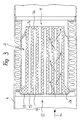
- Fig. 3 a slightly modified embodiment of the body 2 is shown, as used for example for diesel soot filters.
- the channels in the body 2 are not arranged continuously, but alternately at the one and at the other end of the body closed, so that the channel 3a is only open to one end and the adjacent channel 3b is open to the other end.
- Fig. 4 shows an enlarged and again schematically the end view, from which it can be seen that the channels 3a and 3b are alternately closed and open in a checkerboard manner.
- the closure of the channels at the end marked with the arrow 11 has already been manufactured during the manufacture of the body 2 in such a way that the needles used in the manufacturing mold for the formation of the channels 3b are shorter than those for the production of the channels 3a used molding needles so that the free ends of the molding needles are covered with sintered material.
- the channels 3a are closed accordingly and the channels 3b are open.
- the closure takes place here through a perforated plate 13 into which the corresponding passage openings 14 are punched, so that the same configuration results in the front view as in the front view arrow 11, except that the openings are swapped accordingly.
- the perforated plate 13 can be provided in the area of the channels 3a to be closed with features 15, so that here the positive connection between the body 2 and the perforated plate 13, which also serves as a fastening means, is improved.
- the exhaust gas flowing, for example, in the direction of arrow 10 in the exhaust pipe 1 now enters the channels 3b at the end, flows through the partitions between the individual adjacent channels and leaves the body via the channels 3a open at the rear end, as is shown by the curly arrows is shown.
- the soot particles contained in the exhaust gases are retained on the inner wall of the channels 3b.
- the sintered metal body 2 containing the catalytically active material is heated by the hot exhaust gases to a temperature which is in the range of the ignition temperature for the diesel soot reduced by the catalysts, the burn-off takes place even with relatively thin layers of soot, the temperature increase occurring as a result of the burn-up the burn-off of the soot deposits continues over the entire channel area within a very short time.
- the embodiment shown in FIG. 3 can also be used as an exhaust gas catalytic converter for treating the exhaust gases from Otto engines.
- the filter cartridge essentially consists of a flow guide housing 16, which can be cylindrical in cross-section - as shown here - or in another cross-sectional shape, for example oval.
- One end is closed by an intermediate wall 17 and the other end by an intermediate wall 18, which carry a plurality of parallel tubular bodies 19 made of a porous sintered metal in corresponding openings.
- the tubular body 19 are open at one end 20 and closed at the other end 21.
- the intermediate wall 17 is here Provide gas passage openings 22 which are identical to the openings of the tubular body 19, as shown in the front view. 6 and 7 can be seen.
- the intermediate housing wall 18 is provided with through openings 23, through which the end 21 of the tubular body 19 is inserted, and in the remaining spaces with gas passage openings 24.
- Exhaust gases can now flow through the filter cartridge shown in FIG. 5 both from the direction of arrow A and from the direction of arrow B.
- the exhaust gases enter the interior of the tubular body 19 and, as indicated by the arrows 25, flow through the porous walls of the tubular body and enter through the gas passage openings 24 into the subsequent exhaust pipe, not shown.
- the filter body can also be flowed through from the other side, so that there is a correspondingly reversed flow.
- the tubular body 19 are now fixed in the intermediate walls so that one pipe end is fixedly connected to a housing intermediate wall and the other pipe end is held freely displaceably in a corresponding opening.
- the attachment can be done, for example, by welding the pipe end in question.
- a particularly advantageous positive connection is selected.
- a circumferential retaining collar 26 is formed on each tubular body 19 in the region of its open end, the two end faces 27, 28 of which are conically tapered.
- the intermediate housing wall 17 is formed in two parts. Each wall part is produced, for example, by a stamping process, in which the holes with their conical contact surfaces for the end faces 27, 28 of the retaining collar 26 and a subsequent collar 29 are produced in one operation.
- Both wall parts are identical, so that the wall part 17a can be connected to the housing 16, for example by welding, and then the housing partition 18 is also connected to the housing. Then the tubular body 19 is pushed in in the direction of arrow A, the wall part 17b is placed on it, the conical end face 27 is centered, and then welded to the housing 16.
- an additional partition wall not shown here, in the form of the housing partition wall 18, which is arranged between the partition walls 17 and 18 in the housing, can additionally be provided.
- the schematic representation in FIG. 9 shows a permeable-porous monolithic sintered metal body 30, which is arranged in a flow channel 31.
- the body 30 is composed in such a way that it contains, with respect to the gas to be treated, catalytically active constituents which are introduced into the body in one of the production methods explained in the introduction.
- the geometric shape of the sintered metal body 30 depends on the procedural circumstances, which need not be considered here.
- the body has a three-layer structure, with the first layer 30a having a high porosity, with respect to the direction of flow (arrow 32), the second layer 30b being smaller in comparison Porosity and a third layer 30c with in turn reduced porosity.
- a permeable-porous sintered metal block 33 is shown schematically, in which channels 34 with an impermeable wall are molded. If, for example, a block designed in this way is in turn inserted into a flow channel 31, there is the possibility here of passing a flowable heat transfer medium through the channels 34 with impermeable walls, which, depending on the process to be carried out, supplies heat or dissipates heat, so that using the good thermal conductivity of a sintered metal body with a corresponding distribution of such channels over the entire cross-section, a uniform temperature distribution can be achieved.
- the channels 34 can be formed in a targeted manner in the regions of the sintered metal body 33 which require a specific supply or removal of heat.
Landscapes
- Engineering & Computer Science (AREA)
- Chemical & Material Sciences (AREA)
- Chemical Kinetics & Catalysis (AREA)
- Combustion & Propulsion (AREA)
- Mechanical Engineering (AREA)
- General Engineering & Computer Science (AREA)
- Health & Medical Sciences (AREA)
- General Chemical & Material Sciences (AREA)
- Oil, Petroleum & Natural Gas (AREA)
- Toxicology (AREA)
- Analytical Chemistry (AREA)
- Biomedical Technology (AREA)
- Physics & Mathematics (AREA)
- Geometry (AREA)
- Environmental & Geological Engineering (AREA)
- Inorganic Chemistry (AREA)
- Life Sciences & Earth Sciences (AREA)
- Geology (AREA)
- Filtering Materials (AREA)
- Catalysts (AREA)
- Exhaust Gas After Treatment (AREA)
Applications Claiming Priority (4)
| Application Number | Priority Date | Filing Date | Title |
|---|---|---|---|
| DE3922910 | 1989-07-12 | ||
| DE3922909 | 1989-07-12 | ||
| DE3922910A DE3922910A1 (de) | 1989-07-12 | 1989-07-12 | Katalytisch wirkender filter zur reinigung der abgase von verbrennungsmotoren, insbesondere von dieselmotoren |
| DE3922909A DE3922909A1 (de) | 1989-07-12 | 1989-07-12 | Monolithischer poroeser koerper zur behandlung der abgase von verbrennungsmotoren und verfahren zu seiner herstellung |
Publications (1)
| Publication Number | Publication Date |
|---|---|
| EP0410200A1 true EP0410200A1 (fr) | 1991-01-30 |
Family
ID=25882905
Family Applications (1)
| Application Number | Title | Priority Date | Filing Date |
|---|---|---|---|
| EP90113125A Withdrawn EP0410200A1 (fr) | 1989-07-12 | 1990-07-10 | Corps poreux pour le traitement de gaz et/ou des vapeurs et/ou des liquides et son procédé de fabrication |
Country Status (5)
| Country | Link |
|---|---|
| EP (1) | EP0410200A1 (fr) |
| JP (1) | JPH04500777A (fr) |
| KR (1) | KR920700741A (fr) |
| CA (1) | CA2036385A1 (fr) |
| WO (1) | WO1991000770A1 (fr) |
Cited By (10)
| Publication number | Priority date | Publication date | Assignee | Title |
|---|---|---|---|---|
| WO1994025206A1 (fr) * | 1993-04-27 | 1994-11-10 | Gastec N.V. | Corps poreux resistant a la corrosion et son procede de production |
| EP0657202A1 (fr) * | 1993-06-28 | 1995-06-14 | Mitsubishi Jukogyo Kabushiki Kaisha | Dispositif de suppression des poussieres |
| WO1996023134A1 (fr) * | 1995-01-24 | 1996-08-01 | Axel Hartenstein | Dispositif pour elimination de substances sous forme de gaz et de vapeur dans un courant d'air evacue |
| FR2731745A1 (fr) * | 1995-03-15 | 1996-09-20 | Pierburg Gmbh | Montage de filtre a noir de carbone pour moteurs diesel |
| EP0698410B1 (fr) * | 1994-08-04 | 2000-03-08 | Ngk Insulators, Ltd. | Construction de support d'un élément de filtre dans un appareil pour la récupération de poussière |
| WO2004079166A1 (fr) * | 2003-03-07 | 2004-09-16 | Purem Abgassysteme Gmbh & Co. Kg | Element filtrant destine a des particules contenues dans des gaz d'echappement |
| WO2006053750A1 (fr) * | 2004-11-17 | 2006-05-26 | Gvp Gesellschaft Zur Vermarktung Der Porenbrennertechnik Mbh | Dispositif d'epuration de gaz d'echappement contenant de la suie d'un moteur a combustion interne |
| EP1882830A1 (fr) * | 2006-07-20 | 2008-01-30 | Benteler Automotive Corporation | Construction de filtre d'échappement pour diesel |
| ITRE20090001A1 (it) * | 2009-01-15 | 2010-07-16 | Ufi Innovatione Ct S R L | '' filtro antiparticolato e relativo metodo di fabbricazione '' |
| US7901637B2 (en) | 2005-04-14 | 2011-03-08 | Benteler Automobiltechnik Gmbh | Device for exhaust emission purification for vehicles and production method thereof |
Families Citing this family (2)
| Publication number | Priority date | Publication date | Assignee | Title |
|---|---|---|---|---|
| DK98993D0 (da) * | 1993-09-01 | 1993-09-01 | Per Stobbe | Dust filter for hot gases |
| DE10034045A1 (de) | 2000-07-13 | 2002-01-31 | Schumacher Umwelt Trenntech | Keramisches Filterelement und Verfahren zu seiner Herstellung |
Citations (5)
| Publication number | Priority date | Publication date | Assignee | Title |
|---|---|---|---|---|
| DE2155955A1 (de) * | 1971-11-11 | 1973-05-30 | Krebsoege Gmbh Sintermetall | Verfahren zum herstellen eines aus sintermetall bestehenden filters und nach diesem verfahren hergestelltes filter |
| DE2165839A1 (de) * | 1971-12-31 | 1973-07-19 | Duerrwaechter E Dr Doduco | Abgaskatalysator mit traeger |
| DE2536276A1 (de) * | 1975-08-14 | 1977-02-17 | Krebsoege Gmbh Sintermetall | Filterpatrone mit faltenmantel und stuetzkoerper |
| US4416675A (en) * | 1982-02-22 | 1983-11-22 | Corning Glass Works | High capacity solid particulate filter apparatus |
| US4582677A (en) * | 1980-09-22 | 1986-04-15 | Kabushiki Kaisha Kobe Seiko Sho | Method for producing honeycomb-shaped metal moldings |
-
1990
- 1990-07-10 KR KR1019910700254A patent/KR920700741A/ko not_active Application Discontinuation
- 1990-07-10 EP EP90113125A patent/EP0410200A1/fr not_active Withdrawn
- 1990-07-10 WO PCT/EP1990/001118 patent/WO1991000770A1/fr active Application Filing
- 1990-07-10 CA CA002036385A patent/CA2036385A1/fr not_active Abandoned
- 1990-07-10 JP JP2510675A patent/JPH04500777A/ja active Pending
Patent Citations (5)
| Publication number | Priority date | Publication date | Assignee | Title |
|---|---|---|---|---|
| DE2155955A1 (de) * | 1971-11-11 | 1973-05-30 | Krebsoege Gmbh Sintermetall | Verfahren zum herstellen eines aus sintermetall bestehenden filters und nach diesem verfahren hergestelltes filter |
| DE2165839A1 (de) * | 1971-12-31 | 1973-07-19 | Duerrwaechter E Dr Doduco | Abgaskatalysator mit traeger |
| DE2536276A1 (de) * | 1975-08-14 | 1977-02-17 | Krebsoege Gmbh Sintermetall | Filterpatrone mit faltenmantel und stuetzkoerper |
| US4582677A (en) * | 1980-09-22 | 1986-04-15 | Kabushiki Kaisha Kobe Seiko Sho | Method for producing honeycomb-shaped metal moldings |
| US4416675A (en) * | 1982-02-22 | 1983-11-22 | Corning Glass Works | High capacity solid particulate filter apparatus |
Cited By (14)
| Publication number | Priority date | Publication date | Assignee | Title |
|---|---|---|---|---|
| WO1994025206A1 (fr) * | 1993-04-27 | 1994-11-10 | Gastec N.V. | Corps poreux resistant a la corrosion et son procede de production |
| NL9300716A (nl) * | 1993-04-27 | 1994-11-16 | Gastec Nv | Poreus lichaam geschikt voor gebruik in een corrosieve omgeving en een werkwijze voor de vervaardiging daarvan. |
| US5603742A (en) * | 1993-06-28 | 1997-02-18 | Mitsubishi Jukogyo Kabushiki Kaisha | Dust removing apparatus |
| EP0657202A4 (fr) * | 1993-06-28 | 1995-07-19 | ||
| EP0657202A1 (fr) * | 1993-06-28 | 1995-06-14 | Mitsubishi Jukogyo Kabushiki Kaisha | Dispositif de suppression des poussieres |
| EP0698410B1 (fr) * | 1994-08-04 | 2000-03-08 | Ngk Insulators, Ltd. | Construction de support d'un élément de filtre dans un appareil pour la récupération de poussière |
| WO1996023134A1 (fr) * | 1995-01-24 | 1996-08-01 | Axel Hartenstein | Dispositif pour elimination de substances sous forme de gaz et de vapeur dans un courant d'air evacue |
| FR2731745A1 (fr) * | 1995-03-15 | 1996-09-20 | Pierburg Gmbh | Montage de filtre a noir de carbone pour moteurs diesel |
| WO2004079166A1 (fr) * | 2003-03-07 | 2004-09-16 | Purem Abgassysteme Gmbh & Co. Kg | Element filtrant destine a des particules contenues dans des gaz d'echappement |
| WO2006053750A1 (fr) * | 2004-11-17 | 2006-05-26 | Gvp Gesellschaft Zur Vermarktung Der Porenbrennertechnik Mbh | Dispositif d'epuration de gaz d'echappement contenant de la suie d'un moteur a combustion interne |
| US7901637B2 (en) | 2005-04-14 | 2011-03-08 | Benteler Automobiltechnik Gmbh | Device for exhaust emission purification for vehicles and production method thereof |
| EP1882830A1 (fr) * | 2006-07-20 | 2008-01-30 | Benteler Automotive Corporation | Construction de filtre d'échappement pour diesel |
| ITRE20090001A1 (it) * | 2009-01-15 | 2010-07-16 | Ufi Innovatione Ct S R L | '' filtro antiparticolato e relativo metodo di fabbricazione '' |
| WO2010081614A1 (fr) * | 2009-01-15 | 2010-07-22 | Ufi Innovation Center S.R.L. | Filtre anti-particulaire et procédé de fabrication associé |
Also Published As
| Publication number | Publication date |
|---|---|
| WO1991000770A1 (fr) | 1991-01-24 |
| KR920700741A (ko) | 1992-08-10 |
| CA2036385A1 (fr) | 1991-01-13 |
| JPH04500777A (ja) | 1992-02-13 |
Similar Documents
| Publication | Publication Date | Title |
|---|---|---|
| DE3541372C2 (fr) | ||
| DE602004011971T3 (de) | Wabenstruktur | |
| DE69216101T2 (de) | Partikelfilter zur reinigung von dieselmotorabgas | |
| DE3818281A1 (de) | Abgasfilter | |
| DE68928901T2 (de) | Verfahren zur Herstellung eines porösen Filterkörpers | |
| EP0379032B1 (fr) | Filtre de gaz d'échappement | |
| EP0892887A1 (fr) | Corps de filtre a trajets d'ecoulement resistant a la chaleur et pouvant etre regenere | |
| DE60225902T2 (de) | Partikelfilter zum reinigen der abgase von verbrennungsmotoren | |
| EP0387394B1 (fr) | Procédé pour la fabrication du corps d'un filtre ou d'un catalyseur | |
| DE602004000465T2 (de) | Offenporiger formkörper, verfahren zu dessen herstellung und verwendung dieses körpers | |
| EP0505832A1 (fr) | Corps filtrant ou catalytique | |
| DE4022937A1 (de) | Filter- oder katalysatorkoerper | |
| DE60120898T2 (de) | Partikelfilter für Dieselmaschinen | |
| EP0410200A1 (fr) | Corps poreux pour le traitement de gaz et/ou des vapeurs et/ou des liquides et son procédé de fabrication | |
| DE3828347A1 (de) | Abgasfilter fuer heizungs- oder verbrennungsanlagen | |
| DE4438556A1 (de) | Filter, insbesondere zum Filtrieren der Ansaugluft einer Brennkraftmaschine | |
| DE69801257T2 (de) | Abgasreiniger | |
| DE3101026A1 (de) | Bifunktionaler filter zur behandlung von abgasen | |
| EP0086367B1 (fr) | Dispositif de nettoyage des gaz d'échappement des moteurs Diesel, particulièrement pour véhicules | |
| DE4022321A1 (de) | Filter | |
| DE4125686C2 (de) | Abgasfilter für Brennstoffkraftmaschinen und Verfahren zur Herstellung | |
| DE4303586A1 (en) | Exhaust emission controller for IC engine - has tubular filter elements with regenerative heaters embedded in thickened walls and mounted in tubular housing | |
| DE3922909A1 (de) | Monolithischer poroeser koerper zur behandlung der abgase von verbrennungsmotoren und verfahren zu seiner herstellung | |
| DE3922910A1 (de) | Katalytisch wirkender filter zur reinigung der abgase von verbrennungsmotoren, insbesondere von dieselmotoren | |
| EP1664495A1 (fr) | Filtre a particules pour moteur a combustion interne |
Legal Events
| Date | Code | Title | Description |
|---|---|---|---|
| PUAI | Public reference made under article 153(3) epc to a published international application that has entered the european phase |
Free format text: ORIGINAL CODE: 0009012 |
|
| AK | Designated contracting states |
Kind code of ref document: A1 Designated state(s): AT BE CH DE DK ES FR GB GR IT LI LU NL SE |
|
| 17P | Request for examination filed |
Effective date: 19910605 |
|
| 17Q | First examination report despatched |
Effective date: 19930405 |
|
| STAA | Information on the status of an ep patent application or granted ep patent |
Free format text: STATUS: THE APPLICATION IS DEEMED TO BE WITHDRAWN |
|
| 18D | Application deemed to be withdrawn |
Effective date: 19931016 |