EP0410150A2 - Gear pump - Google Patents
Gear pump Download PDFInfo
- Publication number
- EP0410150A2 EP0410150A2 EP19900112100 EP90112100A EP0410150A2 EP 0410150 A2 EP0410150 A2 EP 0410150A2 EP 19900112100 EP19900112100 EP 19900112100 EP 90112100 A EP90112100 A EP 90112100A EP 0410150 A2 EP0410150 A2 EP 0410150A2
- Authority
- EP
- European Patent Office
- Prior art keywords
- pressure
- sealing plate
- pump
- gear
- high pressure
- Prior art date
- Legal status (The legal status is an assumption and is not a legal conclusion. Google has not performed a legal analysis and makes no representation as to the accuracy of the status listed.)
- Withdrawn
Links
Images


Classifications
-
- F—MECHANICAL ENGINEERING; LIGHTING; HEATING; WEAPONS; BLASTING
- F04—POSITIVE - DISPLACEMENT MACHINES FOR LIQUIDS; PUMPS FOR LIQUIDS OR ELASTIC FLUIDS
- F04C—ROTARY-PISTON, OR OSCILLATING-PISTON, POSITIVE-DISPLACEMENT MACHINES FOR LIQUIDS; ROTARY-PISTON, OR OSCILLATING-PISTON, POSITIVE-DISPLACEMENT PUMPS
- F04C14/00—Control of, monitoring of, or safety arrangements for, machines, pumps or pumping installations
- F04C14/24—Control of, monitoring of, or safety arrangements for, machines, pumps or pumping installations characterised by using valves controlling pressure or flow rate, e.g. discharge valves or unloading valves
- F04C14/26—Control of, monitoring of, or safety arrangements for, machines, pumps or pumping installations characterised by using valves controlling pressure or flow rate, e.g. discharge valves or unloading valves using bypass channels
- F04C14/265—Control of, monitoring of, or safety arrangements for, machines, pumps or pumping installations characterised by using valves controlling pressure or flow rate, e.g. discharge valves or unloading valves using bypass channels being obtained by displacing a lateral sealing face
-
- F—MECHANICAL ENGINEERING; LIGHTING; HEATING; WEAPONS; BLASTING
- F04—POSITIVE - DISPLACEMENT MACHINES FOR LIQUIDS; PUMPS FOR LIQUIDS OR ELASTIC FLUIDS
- F04C—ROTARY-PISTON, OR OSCILLATING-PISTON, POSITIVE-DISPLACEMENT MACHINES FOR LIQUIDS; ROTARY-PISTON, OR OSCILLATING-PISTON, POSITIVE-DISPLACEMENT PUMPS
- F04C15/00—Component parts, details or accessories of machines, pumps or pumping installations, not provided for in groups F04C2/00 - F04C14/00
- F04C15/0003—Sealing arrangements in rotary-piston machines or pumps
- F04C15/0023—Axial sealings for working fluid
- F04C15/0026—Elements specially adapted for sealing of the lateral faces of intermeshing-engagement type machines or pumps, e.g. gear machines or pumps
Definitions
- the invention relates to a gear pump according to the preamble of the main claim.
- the sealing plate functions to a certain extent as a current regulator since, when the pressure fields are acted upon accordingly, part of the pressure medium conveyed by the pump can flow directly from the high pressure to the low pressure side along the gear side surfaces. Under certain circumstances, the regulated pressure medium heats up very strongly; it is immediately returned to the suction side of the pump, which can lead to overheating of the pump.
- the gear pump according to the invention with the characterizing features of the main claim has the advantage that the regulated pressure medium is not led to the suction side of the pump, but in the reservoir, where it mixes with the pressure medium there and is cooled accordingly.
- the pump therefore does not draw in pressure medium that has been heated up as intensely as was previously the case.
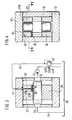
- FIG. 1 shows a longitudinal section through a gear pump, in FIG. 2 a section along II-II according to FIG. 1, in FIG. 3 a section along III-III according to FIG. 2, in FIG. 4 a section along IV-IV according to FIG. 2, in Figures 5 to 8 individual parts in longitudinal section and in plan view, in Figure 9 is a schematic diagram.
- 10 denotes the housing of a gear pump, which has an interior 11 with the cross-sectional shape of an eight and which is closed on both sides by covers 12, 13.
- two gears 14, 15 mesh with one another in external engagement.
- Their shaft journals 16, 17 are mounted in bushings 18 to 21, which are arranged in bores 22 to 25 of glasses-shaped bearing bodies 26, 27, which rest against the covers 12, 13 with little axial play.
- the shaft journal 17 has an extension 17A which penetrates through a bore 13A in the cover 13 and serves to drive the gear pump.
- the sealing plate 30 is arranged in a suitable recess 27A of the glasses 27, has approximately the shape of a three and is located on the high-pressure side HD of the pump.
- the inlet bore 33 is formed in the housing 10, which is connected to the container 35 via a suction line 34.
- the sealing plate 30 only partially covers the gear side surfaces, that is, not even half of them. As already explained above, it is located on the high pressure side and has the shape of a three. Its straight boundary line 30A has a small distance a from an imaginary straight line connecting the shaft centers. Above the sealing plate 30, two of the pressure fields A and B are formed, which are delimited by seals 36, 37. The seal 37 extends around the shaft bores and ends at the boundary line 30A. The seal 36 extends concentrically radially outside and has a certain distance from the inner wall of the housing. The pressure field A is between the seal 36 and the housing inner wall, while the pressure field B is between the two seals.
- the pressure field A is always acted on from the high pressure side - that is, the pump delivery pressure - via a recess 38 which extends along the interior of the housing.
- the pressure field B is acted upon by a small bore 39 which penetrates through the sealing plate 30 - see in particular FIG. 3 in this regard - and ends at the tooth chambers. From this it can be seen that the pressure in the tooth chambers - it is also the delivery pressure of the pump - also prevails in the pressure field B.
- a bore 40 adjoins the bore 39 in the bearing body 27, which bore has a connection to a bore 41 penetrating the cover.
- a line 42 is connected to this bore, in which there is an electromagnetically actuated control valve 43 and which leads to the container 35.
- longitudinal grooves 45, 46 are formed on the two sleeves 18, 19 on their inner sides facing the sealing plate, which extend over the entire length of the sleeves.
- the longitudinal groove is designated 46. In the sectional view of Figure 2, these longitudinal grooves are shown as broad lines (numbers 45, 46).
- a flat recess 27B is formed on the side of the bearing body 27 facing the cover 12.
- FIG. 8 shows a view of this end face of the bearing body 27. From this it can be seen that the recess 27B is relatively narrow, so that on the end face of the bearing body 27 there is still space for a pressure field 27E which acts on the high pressure side and so on is dimensioned that it presses the bearing body slightly against the gear side surfaces.
- the pressure in the pressure field B can be varied continuously by appropriate switching of the solenoid valve 43.
- the valve 43 When the valve 43 is closed, the pump delivery pressure practically prevails in the pressure field B, which - as described above - reaches the pressure field via the bore 39.
- the delivery pressure of the pump always prevails in pressure field A.
- valve 43 If the valve 43 is opened by appropriate actuation of its electromagnet 43A, pressure medium can flow out of the pressure field B via the bores 40, 41 as well as the line 42 and the valve 43 to the container.
- the sealing plate 30 is now more or less lifted off the gear side surfaces by the pressure prevailing below it in the tooth chambers. This allows pressure medium to flow from the high pressure side below the plate. Due to the shape of the pressure plate, this outflowing pressure medium reaches the longitudinal grooves 45, 46 of the bushings 18, 19 and to the recess 27A on the bearing body 27. From there it flows through the bore 48 and through the interior of the gear pump into the container 35.
- the sealing plate 30 can be lifted more or less strongly from the gear side surfaces, as a result of which a more or less large amount of pressure medium can flow from the high pressure side to the longitudinal grooves 45, 46. It can get very hot, but is cooled again by the fact that it flows into the pressure vessel. Thus, no pressure medium heated on the sealing plate by frictional force flows directly to the suction side. If the valve 43 is completely closed, the sealing plate lies fully against the gear side surfaces so that no pressure medium can flow away from the high to the low pressure side. The delivery rate is now maximum.
- the sealing plate has the function of a flow control valve by correspondingly controlling the pressure in the pressure field B, as a result of which the delivery rate of the pump can be regulated in the simplest way. Overheating of the gear pump is reliably avoided in that the pressure medium which is deactivated in the bypass flows to the container and is cooled there.
- the pressure control is shown schematically in FIG.
- the sealing plate 30 is shown here as a bypass valve, which function it also has.
- the current flowing through the sealing plate is designated Q V
- the low pressure medium flow flowing out of the pressure field B is designated Q S. It can be clearly seen here that the pressure medium flowing out via the sealing plate 30 reaches the container 35 directly.
- the pressure in the pressure field B can also be controlled in another way than by means of the control valve 43, for. B. by an external pressure control device (auxiliary pump, hydraulic system, pressure accumulator, etc.).
- a sealing plate 30 can also be arranged on both gear side surfaces, if this is necessary.
Abstract
Description
Die Erfindung geht aus von einer Zahnradpumpe nach der Gattung des Hauptanspruchs. Bei einer derartigen bekannten Zahnradpumpe funktioniert die Dichtplatte gewissermaßen als Stromregler, da bei entsprechender Beaufschlagung der Druckfelder ein Teil des von der Pumpe geförderten Druckmittels entlang der Zahnradseitenflächen unmittelbar von der Hochdruck- zur Niederdruckseite fließen kann. Dabei erwärmt sich das abgeregelte Druckmittel unter Umständen sehr stark; es wird unmittelbar der Saugseite der Pumpe wieder zugeführt, was zu einer Überhitzung der Pumpe führen kann.The invention relates to a gear pump according to the preamble of the main claim. In such a known gear pump, the sealing plate functions to a certain extent as a current regulator since, when the pressure fields are acted upon accordingly, part of the pressure medium conveyed by the pump can flow directly from the high pressure to the low pressure side along the gear side surfaces. Under certain circumstances, the regulated pressure medium heats up very strongly; it is immediately returned to the suction side of the pump, which can lead to overheating of the pump.
Die erfindungsgemäße Zahnradpumpe mit den kennzeichnenden Merkmalen des Hauptanspruchs hat demgegenüber den Vorteil, daß das abgeregelte Druckmittel nicht zur Saugseite der Pumpe geführt wird, sondern in den Vorratsbehälter, wo es sich mit dem dort vorhandenen Druckmittel mischt und entsprechend abgekühlt wird. Die Pumpe saugt also kein so stark erwärmtes Druckmittel an, wie es bisher der Fall war.The gear pump according to the invention with the characterizing features of the main claim has the advantage that the regulated pressure medium is not led to the suction side of the pump, but in the reservoir, where it mixes with the pressure medium there and is cooled accordingly. The pump therefore does not draw in pressure medium that has been heated up as intensely as was previously the case.
Weitere Vorteile der Erfindung ergeben sich aus den Unteransprüchen.Further advantages of the invention emerge from the subclaims.
Die Erfindung ist in der nachfolgenden Beschreibung und Zeichnung näher erläutert. Diese zeigt in Figur 1 einen Längsschnitt durch eine Zahnradpumpe, in Figur 2 einen Schnitt längs II-II nach Figur 1, in Figur 3 einen Schnitt längs III-III nach Figur 2, in Figur 4 einen Schnitt längs IV-IV nach Figur 2, in den Figuren 5 bis 8 Einzelteile im Längsschnitt und in der Draufsicht, in Figur 9 eine Prinzipskizze.The invention is explained in more detail in the following description and drawing. 1 shows a longitudinal section through a gear pump, in FIG. 2 a section along II-II according to FIG. 1, in FIG. 3 a section along III-III according to FIG. 2, in FIG. 4 a section along IV-IV according to FIG. 2, in Figures 5 to 8 individual parts in longitudinal section and in plan view, in Figure 9 is a schematic diagram.
In der Zeichnung ist mit 10 das Gehäuse einer Zahnradpumpe bezeichnet, das einen Innenraum 11 mit der Querschnittsform einer acht aufweist und das beidseitig durch Deckel 12, 13 verschlossen ist. Im Innenraum 11 kämmen zwei Zahnräder 14, 15 im Außeneingriff miteinander. Ihre Wellenzapfen 16, 17 sind in Buchsen 18 bis 21 gelagert, welche in Bohrungen 22 bis 25 von brillenförmigen Lagerkörpern 26, 27 angeordnet sind, welche mit geringem axialem Spiel an den Deckeln 12, 13 anliegen. Der Wellenzapfen 17 hat einen Fortsatz 17A, der durch eine Bohrung 13A im Deckel 13 nach außen dringt und zum Antrieb der Zahnradpumpe dient.In the drawing, 10 denotes the housing of a gear pump, which has an
Zwischen den Seitenflächen der Zähnräder 14, 15 und der Brille 27 ist eine Dichtplatte 30 angeordnet, wie sie in Figur 2 und insbesondere in Figur 7 dargestellt ist. Die Dichtplatte 30 ist in einer passenden Ausnehmung 27A der Brille 27 angeordnet, hat etwa die Form einer Drei und befindet sich auf der Hochdruckseite HD der Pumpe. Dort ist die Auslaßbohrung 31, die in das Innere des Gehäuses mündet und an welche eine Verbraucherleitung 32 angeschlossen ist. Diametral gegenüberliegend ist im Gehäuse 10 die Einlaßbohrung 33 ausgebildet, welche über eine Saugleitung 34 mit dem Behälter 35 in Verbindung steht.A
Die Dichtplatte 30 bedeckt nur teilweise die Zahnradseitenflächen, das heißt nicht einmal die Hälfte derselben. Wie bereits oben ausgeführt, befindet sie sich auf der Hochdruckseite und hat etwa die Form einer Drei. Ihre gerade Begrenzungslinie 30A hat einen geringen Abstand a gegenüber einer die Wellenmitten verbindenden gedachten Geraden. Oberhalb der Dichtplatte 30 sind zwei der Druckfelder A und B ausgebildet, welche durch Dichtungen 36, 37 begrenzt sind. Die Dichtung 37 erstreckt sich um die Wellenbohrungen herum und endet an der Begrenzungslinie 30A. Radial außerhalb verläuft konzentrisch die Dichtung 36, sie hat einen bestimmten Abstand zur Gehäuseinnenwand. Das Druckfeld A befindet sich zwischen der Dichtung 36 und der Gehäuseinnenwand, während sich das Druckfeld B zwischen den beiden Dichtungen befindet. Das Druckfeld A ist stets von der Hochdruckseite - das heißt vom Pumpenförderdruck - beaufschlagt, und zwar über eine Ausnehmung 38, die sich entlang des Gehäuseinnenraums erstreckt. Das Druckfeld B ist über eine kleine Bohrung 39 beaufschlagt, welche durch die Dichtplatte 30 hindurchdringt - siehe hierzu insbesondere Figur 3 - und endet an den Zahnkammern. Daraus ist zu erkennen, daß der Druck in den Zahnkammern - es ist ebenfalls etwa der Förderdruck der Pumpe - auch im Druckfeld B herrscht.The
An die Bohrung 39 schließt sich im Lagerkörper 27 eine Bohrung 40 an, welche Verbindung zu einer den Deckel durchdringenden Bohrung 41 hat. An diese Bohrung ist eine Leitung 42 angeschlossen, in welcher sich ein elektromagnetisch betätigbares Steuerventil 43 befindet und die zum Behälter 35 führt. An den beiden Buchsen 18, 19 sind an ihren der Dichtplatte zugewandten Innenseiten relativ breite, d. h. groß dimensionierte Längsnuten 45, 46 ausgebildet, welche sich über die gesamte Länge der Buchsen erstrecken. In den Figuren 5 und 6 ist nur die Lagerbuchse 18 gezeichnet, die Lagerbuchse 19 ist ebenso ausgebildet, deren Längsnut ist mit 46 bezeichnet. Im Schnittbild nach Figur 2 sind diese Längsnuten als breite Linien dargestellt (Ziffern 45, 46). An der dem Deckel 12 zugewandten Seite des Lagerkörpers 27 ist eine flache Ausnehmung 27B ausgebildet. In diese Ausnehmung münden die Längsnuten 45, 46 an den Buchsen 18, 19. Von der Ausnehmung 27B führt ein Kanal 48 entlang des Lagerkörpers zum Inneren des Gehäuses und dann zum Behälter 35, also nicht zur Saugseite der Pumpe, was wesentlich ist. Die Figur 8 zeigt eine Ansicht auf diese Stirnseite des Lagerkörpers 27. Daraus ist zu erkennen, daß die Ausnehmung 27B verhältnismäßig schmal ist, so daß auf der Stirnseite des Lagerkörpers 27 noch Platz bleibt für ein Druckfeld 27E, das von der Hochdruckseite her beaufschlagt und so dimensioniert ist, daß es den Lagerkörper leicht an die Zahnradseitenflächen drückt.A
Durch entsprechende Schaltung des Elektromagnetventils 43 kann der Druck im Druckfeld B stufenlos variiert werden. Wenn das Ventil 43 geschlossen ist, herrscht im Druckfeld B praktisch der Pumpenförderdruck, der - wie oben beschrieben - über die Bohrung 39 in das Druckfeld gelangt. Im Druckfeld A herrscht stets der Förderdruck der Pumpe.The pressure in the pressure field B can be varied continuously by appropriate switching of the
Wird das Ventil 43 durch entsprechende Ansteuerung seines Elektromagneten 43A geöffnet, so kann aus dem Druckfeld B Druckmittel über die Bohrungen 40, 41 sowie die Leitung 42 und das Ventil 43 zum Behälter abströmen. Je nach Öffnungsgrad des Ventils 43 und der damit verbundenen Druckabsenkung im Druckfeld B wird nun die Dichtplatte 30 durch den unterhalb von ihr in den Zahnkammern herrschenden Druck mehr oder weniger stark von den Zahnradseitenflächen abgehoben. Dadurch kann Druckmittel von der Hochdruckseite unterhalb der Platte abströmen. Durch die Form der Druckplatte gelangt dieses abströmende Druckmittel in die Längsnuten 45, 46 der Buchsen 18, 19 und zur Ausnehmung 27A am Lagerkörper 27. Von dort fließt es über die Bohrung 48 und durch das Innere der Zahnradpumpe in den Behälter 35 ab. Entsprechend dem Steuerdruck im Druckfeld B kann die Dichtplatte 30 mehr oder weniger stark von den Zahnradseitenflächen abgehoben werden, wodurch eine mehr oder weniger große Druckmittelmenge von der Hochdruckseite zu den Längsnuten 45, 46 abströmen kann. Dabei erwärmt es sich unter Umständen sehr stark, wird aber dadurch, daß es in den Druckbehälter fließt, wieder abgekühlt. Es fließt somit kein an der Dichtplatte durch Reibungskraft erwärmtes Druckmittel unmittelbar zur Saugseite. Ist das Ventil 43 völlig geschlossen, so liegt die Dichtplatte voll an den Zahnradseitenflächen an, so daß kein Druckmittel mehr von der Hoch- zur Niederdruckseite abfließen kann. Die Fördermenge ist nun maximal. Hieraus ist zu erkennen, daß die Dichtplatte durch entsprechende Steuerung des Druckes im Druckfeld B die Funktion eines Stromregelventils hat, wodurch die Fördermenge der Pumpe auf einfachste Weise geregelt werden kann. Eine Überhitzung der Zahnradpumpe wird sicher dadurch vermieden, daß das im Bypass abgesteuerte Druckmittel zum Behälter fließt und dort gekühlt wird.If the
In Figur 8 ist die Drucksteuerung schematisch wiedergegeben. Die Dichtplatte 30 ist hier als Bypassventil dargestellt, welche Funktion sie ja auch hat. Der über die Dichtplatte abfließende Strom ist mit QV bezeichnet, der aus dem Druckfeld B abströmende geringe Druckmittelstrom mit QS. Hier ist gut zu erkennen, daß das über die Dichtplatte 30 abströmende Druckmittel unmittelbar in den Behälter 35 gelangt.The pressure control is shown schematically in FIG. The
Es ist noch zu bemerken, daß der Druck im Druckfeld B auch noch auf andere Weise gesteuert werden kann, als mittels des Steuerventils 43, z. B. durch eine externe Drucksteuereinrichtung (Hilfspumpe, Hydraulikanlage, Druckspeicher etc.). Außerdem kann auch an beiden Zahnradseitenflächen eine Dichplatte 30 angeordnet sein, falls dies erforderlich ist.It should also be noted that the pressure in the pressure field B can also be controlled in another way than by means of the
Claims (5)
Applications Claiming Priority (2)
| Application Number | Priority Date | Filing Date | Title |
|---|---|---|---|
| DE3924482 | 1989-07-25 | ||
| DE19893924482 DE3924482A1 (en) | 1989-07-25 | 1989-07-25 | GEAR PUMP |
Publications (2)
| Publication Number | Publication Date |
|---|---|
| EP0410150A2 true EP0410150A2 (en) | 1991-01-30 |
| EP0410150A3 EP0410150A3 (en) | 1991-11-27 |
Family
ID=6385721
Family Applications (1)
| Application Number | Title | Priority Date | Filing Date |
|---|---|---|---|
| EP19900112100 Withdrawn EP0410150A3 (en) | 1989-07-25 | 1990-06-26 | Gear pump |
Country Status (2)
| Country | Link |
|---|---|
| EP (1) | EP0410150A3 (en) |
| DE (1) | DE3924482A1 (en) |
Cited By (3)
| Publication number | Priority date | Publication date | Assignee | Title |
|---|---|---|---|---|
| WO2012048940A2 (en) | 2010-10-14 | 2012-04-19 | Robert Bosch Gmbh | Gear pump for delivering a fluid |
| CN108612651A (en) * | 2018-07-13 | 2018-10-02 | 杜马司科学仪器(江苏)有限公司 | A kind of vacuum liquid discharging pump and vacuum distillation apparatus |
| CN108678948A (en) * | 2018-04-28 | 2018-10-19 | 河南航天液压气动技术有限公司 | A kind of hydraulic system and its gear pump |
Families Citing this family (2)
| Publication number | Priority date | Publication date | Assignee | Title |
|---|---|---|---|---|
| DE4423096A1 (en) * | 1994-07-01 | 1996-01-04 | Alois Boerger | Rotary pump esp. for fluids with solid content |
| DE102010050163A1 (en) | 2010-10-30 | 2012-05-03 | Iav Gmbh Ingenieurgesellschaft Auto Und Verkehr | Displacement machine for combustion engine of motor vehicle, has nozzle that is arranged at one end of return line to re-circulate pressurized fluid injected in direction of suction opening so that displacement is accelerated |
Citations (6)
| Publication number | Priority date | Publication date | Assignee | Title |
|---|---|---|---|---|
| DE944595C (en) * | 1950-06-16 | 1956-06-21 | Borg Warner | High pressure fluid gear pump |
| DE1528954A1 (en) * | 1964-08-08 | 1970-07-02 | Bosch Gmbh Robert | Displacement machine |
| FR2294053A1 (en) * | 1974-12-12 | 1976-07-09 | Jacquard Systems | METHOD AND MACHINE FOR STAMPING CHARACTERS IN A SOFT MATERIAL |
| DE2903545A1 (en) * | 1978-02-07 | 1979-08-09 | Fuelmaster Prod Nv | ROTATING DISPLACEMENT PUMP, IN PARTICULAR GEAR PUMP |
| EP0012328A1 (en) * | 1978-12-13 | 1980-06-25 | Werdohler Pumpenfabrik Rickmeier GmbH | Gear pump for water or the like |
| WO1989002515A1 (en) * | 1987-09-10 | 1989-03-23 | Robert Bosch Gmbh | Gearwheel motor |
-
1989
- 1989-07-25 DE DE19893924482 patent/DE3924482A1/en active Granted
-
1990
- 1990-06-26 EP EP19900112100 patent/EP0410150A3/en not_active Withdrawn
Patent Citations (6)
| Publication number | Priority date | Publication date | Assignee | Title |
|---|---|---|---|---|
| DE944595C (en) * | 1950-06-16 | 1956-06-21 | Borg Warner | High pressure fluid gear pump |
| DE1528954A1 (en) * | 1964-08-08 | 1970-07-02 | Bosch Gmbh Robert | Displacement machine |
| FR2294053A1 (en) * | 1974-12-12 | 1976-07-09 | Jacquard Systems | METHOD AND MACHINE FOR STAMPING CHARACTERS IN A SOFT MATERIAL |
| DE2903545A1 (en) * | 1978-02-07 | 1979-08-09 | Fuelmaster Prod Nv | ROTATING DISPLACEMENT PUMP, IN PARTICULAR GEAR PUMP |
| EP0012328A1 (en) * | 1978-12-13 | 1980-06-25 | Werdohler Pumpenfabrik Rickmeier GmbH | Gear pump for water or the like |
| WO1989002515A1 (en) * | 1987-09-10 | 1989-03-23 | Robert Bosch Gmbh | Gearwheel motor |
Cited By (4)
| Publication number | Priority date | Publication date | Assignee | Title |
|---|---|---|---|---|
| WO2012048940A2 (en) | 2010-10-14 | 2012-04-19 | Robert Bosch Gmbh | Gear pump for delivering a fluid |
| DE102010042455A1 (en) | 2010-10-14 | 2012-04-19 | Robert Bosch Gmbh | Gear pump for conveying a liquid |
| CN108678948A (en) * | 2018-04-28 | 2018-10-19 | 河南航天液压气动技术有限公司 | A kind of hydraulic system and its gear pump |
| CN108612651A (en) * | 2018-07-13 | 2018-10-02 | 杜马司科学仪器(江苏)有限公司 | A kind of vacuum liquid discharging pump and vacuum distillation apparatus |
Also Published As
| Publication number | Publication date |
|---|---|
| DE3924482C2 (en) | 1991-05-16 |
| DE3924482A1 (en) | 1991-02-07 |
| EP0410150A3 (en) | 1991-11-27 |
Similar Documents
| Publication | Publication Date | Title |
|---|---|---|
| DE19500749C2 (en) | Three-way or multi-way valve | |
| EP0103250B1 (en) | Fluid control control valve | |
| DE4224973C2 (en) | Fluid supply system with pressure limitation | |
| EP0377617B1 (en) | Gearwheel motor | |
| EP0650558B1 (en) | Control device for at least one hydraulic consumer | |
| DE2523894C3 (en) | Hydraulic servo motor system | |
| DE102012001369B4 (en) | Adjustable hydraulic pump | |
| WO1993024346A1 (en) | Hydraulic pump driven by an internal combustion engine | |
| DE102007039302A1 (en) | Hydraulic system | |
| EP0410150A2 (en) | Gear pump | |
| DE2349304C3 (en) | Gear motor operated with hydraulic fluid | |
| DE4118932A1 (en) | PRESSURE LIMIT VALVE | |
| DE3308574A1 (en) | CONTROL VALVE | |
| WO1995033136A1 (en) | Hoisting-gear control system with control valve | |
| EP0445529A1 (en) | Hydraulic device | |
| WO2008031390A1 (en) | Hydraulic system for the supply of a hydraulic fluid to a consumer | |
| DE19717807B4 (en) | From at least one electromagnet operable directional control valve | |
| DE19500748C2 (en) | Three-way or multi-way valve | |
| DE4036696C2 (en) | Diaphragm pump | |
| DE10023583A1 (en) | Electro-hydraulic lowering module, to control the load moved by a hydraulic motor, has a seat valve with its function integrated in the pressure balance in a simple structure with an emergency cut-out | |
| DE3919939C2 (en) | Hydrostatic drive | |
| EP0342346A2 (en) | Gear pump | |
| DE19948390B4 (en) | valve assembly | |
| DE10224827A1 (en) | Hydraulic valve arrangement | |
| DE3902139A1 (en) | HYDROSTATIC DRIVE |
Legal Events
| Date | Code | Title | Description |
|---|---|---|---|
| PUAI | Public reference made under article 153(3) epc to a published international application that has entered the european phase |
Free format text: ORIGINAL CODE: 0009012 |
|
| AK | Designated contracting states |
Kind code of ref document: A2 Designated state(s): DE FR GB IT |
|
| PUAL | Search report despatched |
Free format text: ORIGINAL CODE: 0009013 |
|
| AK | Designated contracting states |
Kind code of ref document: A3 Designated state(s): DE FR GB IT |
|
| RHK1 | Main classification (correction) |
Ipc: F04C 2/14 |
|
| RAP3 | Party data changed (applicant data changed or rights of an application transferred) |
Owner name: ROBERT BOSCH GMBH |
|
| 17P | Request for examination filed |
Effective date: 19920502 |
|
| 17Q | First examination report despatched |
Effective date: 19930125 |
|
| STAA | Information on the status of an ep patent application or granted ep patent |
Free format text: STATUS: THE APPLICATION IS DEEMED TO BE WITHDRAWN |
|
| 18D | Application deemed to be withdrawn |
Effective date: 19940213 |