EP0410094A1 - Tongs for discharge of billets from an induction heating device - Google Patents
Tongs for discharge of billets from an induction heating device Download PDFInfo
- Publication number
- EP0410094A1 EP0410094A1 EP90109323A EP90109323A EP0410094A1 EP 0410094 A1 EP0410094 A1 EP 0410094A1 EP 90109323 A EP90109323 A EP 90109323A EP 90109323 A EP90109323 A EP 90109323A EP 0410094 A1 EP0410094 A1 EP 0410094A1
- Authority
- EP
- European Patent Office
- Prior art keywords
- pliers
- induction heating
- halves
- block
- tongs
- Prior art date
- Legal status (The legal status is an assumption and is not a legal conclusion. Google has not performed a legal analysis and makes no representation as to the accuracy of the status listed.)
- Withdrawn
Links
Images
Classifications
-
- F—MECHANICAL ENGINEERING; LIGHTING; HEATING; WEAPONS; BLASTING
- F27—FURNACES; KILNS; OVENS; RETORTS
- F27D—DETAILS OR ACCESSORIES OF FURNACES, KILNS, OVENS, OR RETORTS, IN SO FAR AS THEY ARE OF KINDS OCCURRING IN MORE THAN ONE KIND OF FURNACE
- F27D3/00—Charging; Discharging; Manipulation of charge
- F27D3/0024—Charging; Discharging; Manipulation of charge of metallic workpieces
-
- F—MECHANICAL ENGINEERING; LIGHTING; HEATING; WEAPONS; BLASTING
- F27—FURNACES; KILNS; OVENS; RETORTS
- F27D—DETAILS OR ACCESSORIES OF FURNACES, KILNS, OVENS, OR RETORTS, IN SO FAR AS THEY ARE OF KINDS OCCURRING IN MORE THAN ONE KIND OF FURNACE
- F27D3/00—Charging; Discharging; Manipulation of charge
- F27D2003/0034—Means for moving, conveying, transporting the charge in the furnace or in the charging facilities
- F27D2003/0068—Means for moving, conveying, transporting the charge in the furnace or in the charging facilities comprising clamps or tongs
-
- F—MECHANICAL ENGINEERING; LIGHTING; HEATING; WEAPONS; BLASTING
- F27—FURNACES; KILNS; OVENS; RETORTS
- F27D—DETAILS OR ACCESSORIES OF FURNACES, KILNS, OVENS, OR RETORTS, IN SO FAR AS THEY ARE OF KINDS OCCURRING IN MORE THAN ONE KIND OF FURNACE
- F27D99/00—Subject matter not provided for in other groups of this subclass
- F27D99/0001—Heating elements or systems
- F27D99/0006—Electric heating elements or system
- F27D2099/0015—Induction heating
-
- F—MECHANICAL ENGINEERING; LIGHTING; HEATING; WEAPONS; BLASTING
- F27—FURNACES; KILNS; OVENS; RETORTS
- F27M—INDEXING SCHEME RELATING TO ASPECTS OF THE CHARGES OR FURNACES, KILNS, OVENS OR RETORTS
- F27M2001/00—Composition, conformation or state of the charge
- F27M2001/15—Composition, conformation or state of the charge characterised by the form of the articles
- F27M2001/1539—Metallic articles
- F27M2001/1547—Elongated articles, e.g. beams, rails
- F27M2001/1552—Billets, slabs
-
- Y—GENERAL TAGGING OF NEW TECHNOLOGICAL DEVELOPMENTS; GENERAL TAGGING OF CROSS-SECTIONAL TECHNOLOGIES SPANNING OVER SEVERAL SECTIONS OF THE IPC; TECHNICAL SUBJECTS COVERED BY FORMER USPC CROSS-REFERENCE ART COLLECTIONS [XRACs] AND DIGESTS
- Y02—TECHNOLOGIES OR APPLICATIONS FOR MITIGATION OR ADAPTATION AGAINST CLIMATE CHANGE
- Y02P—CLIMATE CHANGE MITIGATION TECHNOLOGIES IN THE PRODUCTION OR PROCESSING OF GOODS
- Y02P10/00—Technologies related to metal processing
- Y02P10/25—Process efficiency
Definitions
- the invention relates to a pair of pliers for removing blocks from an induction heating system with two pliers halves which are positively guided in opposite directions at right angles to the conveying direction when the pliers are opened and closed.
- the difficulty in operating induction heating systems for heating metallic blocks is that the blocks stick together when conveyed through the induction heating system at the end faces on which they lie one after the other as they pass through the induction heating system, so that they often do not It is easily possible to pull the block in the direction of conveyance with the extraction tongs of conventional design without the subsequent blocks from the induction heating system.
- the invention is based on the object of improving a device of the type mentioned at the outset in such a way that the bloch lying as the foremost in the induction heating position, separated from the subsequent blocks, can be removed from the induction heating system.
- jaws are articulated on the jaw halves via levers against the pressure of at least one spring which, in the starting position, extend obliquely from the tong halves at an acute angle a to the conveying direction.
- each jaw is articulated in parallelogram fashion via two levers on the associated pliers half and is spaced apart from the pliers half by the force of at least one compression spring.
- the solution according to the invention is based on the fact that it cannot be avoided in induction heating systems in which the blocks with their end faces lying against each other are transported through the induction heating system that the blocks stick to one another at the contact surfaces.
- the invention is based on the consideration that means must be provided by which the foremost block, which is to be drawn separately from the others from the induction heating system, in the simplest and most effective manner when gripping by means of the extraction pliers from the subsequent block to which it sticks is released. This is done in the device according to the invention by means of the jaws which are resiliently pivoted on the pliers halves via levers. These come into contact with the block during the movement of the pliers, while the jaws are still at a distance from the halves of the pliers due to the action of the compression springs.
- the link levers ensure that the jaws are located between the halves of the jaws and the jaw block them clamped by a short distance in the direction of transport, whereby the block ready for removal is torn off from the next block.
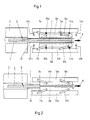
- the foremost block 1 is already almost completely outside the induction heating system 2 in the position for being pulled out completely by detaching the adhesive connection 3 formed in the induction heating system 2 with the subsequent block 4.
- the removal tongs, consisting of the two pliers halves 5a, 5b is in the open starting position for gripping and completely pulling out the block 1 from the induction heating system 2.
- a jaw 6a, 6b is articulated on the pliers halves 5a, 5b via levers 7a, 7b and 8a, 8b.
- levers 7, 8 are at an angle a to the conveying axis of block 1 and run obliquely on the Conveying direction 9 to; as Fig. 1 makes clear.
- compression springs 10a, 10b and 11a, 11b keeps the jaws 6 at a distance from the pliers halves 5.
Abstract
Description
Die Erfindung betrifft eine Zange zur Entnahme von Blöcken aus einer Induktions-Erwärmungsanlage mit zwei im rechten Winkel zur Förderrichtung beim tiffnen und Schließen der Zange jeweils in entgegengesetzte Richtungen zwangsgeführten Zangenhälften.The invention relates to a pair of pliers for removing blocks from an induction heating system with two pliers halves which are positively guided in opposite directions at right angles to the conveying direction when the pliers are opened and closed.
Die Schwierigkeit beim Betrieb von Induktions-Erwärmungsanlagen für die Erwärmung metallischer Blöcke besteht darin, daß die Blöcke beim Fördern durch die Induktions-Erwärmungsanlage an den Endflächen, an denen sie beim Durchlaufen der Induktions-Erwärmungsanlage nacheinander anliegen, miteinander verkleben, so daß es häufig nicht ohne weiteres möglich ist, den in Förderrichtung jeweils vordersten Block mit der Entnahmezange herkömmlicher Bauart ohne die nachfolgenden Blöcke aus der Induktions-Erwärmungsanlage zu ziehen.The difficulty in operating induction heating systems for heating metallic blocks is that the blocks stick together when conveyed through the induction heating system at the end faces on which they lie one after the other as they pass through the induction heating system, so that they often do not It is easily possible to pull the block in the direction of conveyance with the extraction tongs of conventional design without the subsequent blocks from the induction heating system.
Der Erfindung liegt nun die Aufgabe zugrunde, eine Vorrichtung der eingangs genannten Gattung dahingehend zu verbessern, daß der als vorderster in der Induktions-Erwärmungslage liegende Bloch, von der nachfolgenden Blöcken getrennt, aus der Induktions-Erwärmungsanlage gezogen werden kann.The invention is based on the object of improving a device of the type mentioned at the outset in such a way that the bloch lying as the foremost in the induction heating position, separated from the subsequent blocks, can be removed from the induction heating system.
Zur Lösung dieser Aufgabe wird bei der gattungsgemäßen Vorrichtung erfindungsgemäß vorgeschlagen, daß an den Zangenhälften Backen über Hebel gegen den Druck mindestens einer Feder angelenkt sind, die sich in der Ausgangsstellung, von den Zangenhälften in spitzem Winkel a schräg auf die Förderrichtung zulaufend, erstrecken.To achieve this object, it is proposed according to the invention in the generic device that jaws are articulated on the jaw halves via levers against the pressure of at least one spring which, in the starting position, extend obliquely from the tong halves at an acute angle a to the conveying direction.
Gemäß einer bevorzugten Ausgestaltung der erfindungsgemäßen Vorrichtung ist vorgesehene daß jede Backe über zwei Hebel an der zugehörigen Zangenhälfte parallelogrammartig angelenkt und durch die Kraft mindestens einer Druckfeder gegenüber der zangenhälfte beabstandet ist.According to a preferred embodiment of the device according to the invention, it is provided that each jaw is articulated in parallelogram fashion via two levers on the associated pliers half and is spaced apart from the pliers half by the force of at least one compression spring.
Die erfindungsgemäße Lösung geht davon aus, daß es bei Induktions-Erwärmungsanlagen, in denen die Blöcken mit ihren Stirnflächen aneinanderliegend, durch die Induktions-Erwärmungsanlage transportiert werden, nicht zu vermeiden ist, daß die Blöcke an den Berührungsflächen miteinander verkleben. Die Erfindung beruht auf der Überlegung, daß Mittel vorgesehen werden müssen, durch die der vorderste Block, der getrennt von den anderen aus der Induktions-Erwärmungsanlage gezogen werden soll, auf möglichst einfache und wirksame Weise beim Ergreifen mittels der Entnahmezange von dem nachfolgenden Block, an welchem er klebt, gelöst wird. Dies geschieht bei der erfindungsgemäßen Vorrichtung mittels der an den Zangenhälften federnd über Hebel schwenkbar gelagerten Backen. Diese kommen bei der Zangenbewegung mit dem Block in Berührung, während die Backen aufgrund der Wirkung der Druckfedern noch im Abstand zu den Zangenhälften stehen.The solution according to the invention is based on the fact that it cannot be avoided in induction heating systems in which the blocks with their end faces lying against each other are transported through the induction heating system that the blocks stick to one another at the contact surfaces. The invention is based on the consideration that means must be provided by which the foremost block, which is to be drawn separately from the others from the induction heating system, in the simplest and most effective manner when gripping by means of the extraction pliers from the subsequent block to which it sticks is released. This is done in the device according to the invention by means of the jaws which are resiliently pivoted on the pliers halves via levers. These come into contact with the block during the movement of the pliers, while the jaws are still at a distance from the halves of the pliers due to the action of the compression springs.
Wenn die Backen mit dem Block in Berührung sind und die Zangenhälften weiter in Richtung aufeinander zu gegen den Druck der Federn zwischen ihnen und den Backen weiterbewegt werden, dann sorgen die Anlenkhebel aufgrund ihrer Lage zwischen Zangenhälfte und Backe dafür, daß sich die Backen mit dem zwischen ihnen eingespannten Block um eine kurze Wegstrecke in Transportrichtung ruckartig bewegen, wodurch der zur Entnahme bereitliegende Block von dem nachfolgenden Block abgerissen wird.When the jaws are in contact with the block and the halves of the pliers are moved further towards each other against the pressure of the springs between them and the jaws, the link levers ensure that the jaws are located between the halves of the jaws and the jaw block them clamped by a short distance in the direction of transport, whereby the block ready for removal is torn off from the next block.
Anhand des in der Zeichnung dargestellten Ausführungsbeispiels wird die Erfindung näher erläutert. Es zeigen:
- Fig. 1 die Zange in der Ausgangsstellung und
- Fig. 2 in der Eingriffsstellung mit dem Block.
- Fig. 1 the pliers in the starting position and
- Fig. 2 in the engaged position with the block.
Bei der in Fig 1 dargestellten Ausgangslage liegt der vorderste Block 1 bereits fast vollständig außerhalb der Induktions-Erwärmungsanlage 2 in der Stellung zum vollständigen Herausziehen unter Ablösen der in der Induktions-Erwärmungsanlage 2 entstandenen Klebeverbindung 3 mit dem nachfolgenden Block 4. Die Entnahmezange, bestehend aus den beiden Zangenhälften 5a,5b, befindet sich in der geöffneten Ausgangsstellung zum Ergreifen und vollständigen Herausziehen des Blocks 1 aus der Induktions-Erwärmungsanlage 2.In the starting position shown in FIG. 1, the
An den Zangenhälften 5a,5b ist jeweils eine Backe 6a,6b über Hebel 7a,7b und 8a,8b angelenkt Die Hebel 7,8 stehen in der Ausgangsstellung der Fig. 1 in einem Winkel a zur Förderachse des Blocks 1 und verlaufen schräg auf die Förderrichtung 9 zu; wie Fig. 1 deutlich macht.A
Durch die Wirkung von Druckfedern 10a,10b und 11a,11b werden die Backen 6 auf Abstand zu den Zangenhälften 5 gehalten.The action of compression springs 10a, 10b and 11a, 11b keeps the jaws 6 at a distance from the
Wenn die Zangenhälften 5 in Pfeilrichtung 12a,12b aufeinander/zubewegt werden, um den Block 1 zu ergreifen, kommen zunächst die Backen 6 mit dem spießkantig auf einer Schiene 13 liegenden Block 1 in Berührung. Da sie dann durch den Block 1 an einer Weiterbewegung gehindert sind, folgt bei weiterem Aufeinanderzubewegen der Zangenhälften 5a,5b in Pfeilrichtung 12 unter Zusammenpressen der Federn 10,11 über die Hebel 7,8 ein Vorschub der Backen 6 in Förderrichtung 9. Dadurch reißt der Block 1 an der Klebestelle 3 von dem nachfolgenden Block 4 automatisch ab und kann nach dem vollständigen Schließen der Zange (Fig. 2) in Förderrichtung 9 abtransportiert werden.When the
- 1 - Block1 - block
- 2 - Induktions-Erwärmungsanlage2 - Induction heating system
- 3 - Klebverbindung3 - adhesive connection
- 4 - Block4 - block
- 5 - Zange5 - pliers
- 6 - Backe6 - cheek
- 7 - Hebel7 - lever
- 8 - Hebel8 - lever
- 9 - Förderrichtung9 - Direction of conveyance
- 10 - Feder10 - spring
- 11 - Feder11 - spring
- 12 - Pfeilrichtung12 - direction of arrow
- 13 - Schiene13 - rail
Claims (2)
dadurch gekennzeichnet, daß an den Zangenhälften (5) Backen (6) über Hebel (7,8) gegen den Druck mindestens einer Feder (10,11) angelenkt sind, die sich in der Ausgangsstellung, von den Zangenhälften in spitzem Winkel (a) schräg auf die Förderrichtung (9) zulaufend, erstrecken.1. Pliers for removing blocks from an induction heating system with two pliers halves which are positively guided in opposite directions at right angles to the conveying direction when the pliers are opened and closed,
characterized in that the jaw halves (5) jaws (6) are articulated via levers (7, 8) against the pressure of at least one spring (10, 11) which, in the starting position, is at an acute angle (a) from the jaw halves extend obliquely to the conveying direction (9).
dadurch gekennzeichnet, daß jede Backe (6) über zwei Hebel (7,8) an der zugehörigen Zangenhälfte (5) parallelogrammartig an gelenkt und durch die Kraft mindestens einer Druckfeder (10,11) gegenüber der Zangenhälfte (5) beabstandet ist.2. Pliers according to claim 1,
characterized in that each jaw (6) is steered in parallelogram fashion via two levers (7, 8) on the associated pliers half (5) and is spaced apart from the pliers half (5) by the force of at least one compression spring (10, 11).
Applications Claiming Priority (2)
| Application Number | Priority Date | Filing Date | Title |
|---|---|---|---|
| DE3924641A DE3924641C1 (en) | 1989-07-26 | 1989-07-26 | |
| DE3924641 | 1989-07-26 |
Publications (1)
| Publication Number | Publication Date |
|---|---|
| EP0410094A1 true EP0410094A1 (en) | 1991-01-30 |
Family
ID=6385822
Family Applications (1)
| Application Number | Title | Priority Date | Filing Date |
|---|---|---|---|
| EP90109323A Withdrawn EP0410094A1 (en) | 1989-07-26 | 1990-05-17 | Tongs for discharge of billets from an induction heating device |
Country Status (3)
| Country | Link |
|---|---|
| EP (1) | EP0410094A1 (en) |
| BR (1) | BR9003604A (en) |
| DE (1) | DE3924641C1 (en) |
Cited By (1)
| Publication number | Priority date | Publication date | Assignee | Title |
|---|---|---|---|---|
| US5181412A (en) * | 1990-03-30 | 1993-01-26 | Peter Lisec | Apparatus bending hollow profiles into spacer frames for insulating glass |
Families Citing this family (1)
| Publication number | Priority date | Publication date | Assignee | Title |
|---|---|---|---|---|
| CN111646212B (en) * | 2020-06-04 | 2022-08-12 | 安徽飞镖知识产权服务股份有限公司 | Green brick transfer trolley positioning device for sludge brick making production |
Citations (2)
| Publication number | Priority date | Publication date | Assignee | Title |
|---|---|---|---|---|
| DE3134784C2 (en) * | 1981-06-12 | 1985-02-21 | Maag-Zahnräder & -Maschinen AG, Zürich | Clamping chuck for a device for handling workpieces |
| EP0311819A1 (en) * | 1987-10-14 | 1989-04-19 | Günter Meywald | Hold-down jaw |
Family Cites Families (1)
| Publication number | Priority date | Publication date | Assignee | Title |
|---|---|---|---|---|
| DE2709218A1 (en) * | 1977-03-03 | 1978-09-07 | Aeg Elotherm Gmbh | INDUCTION THROUGH FURNACE FOR HEATING METALLIC WORKPIECES |
-
1989
- 1989-07-26 DE DE3924641A patent/DE3924641C1/de not_active Expired - Lifetime
-
1990
- 1990-05-17 EP EP90109323A patent/EP0410094A1/en not_active Withdrawn
- 1990-07-25 BR BR909003604A patent/BR9003604A/en unknown
Patent Citations (2)
| Publication number | Priority date | Publication date | Assignee | Title |
|---|---|---|---|---|
| DE3134784C2 (en) * | 1981-06-12 | 1985-02-21 | Maag-Zahnräder & -Maschinen AG, Zürich | Clamping chuck for a device for handling workpieces |
| EP0311819A1 (en) * | 1987-10-14 | 1989-04-19 | Günter Meywald | Hold-down jaw |
Cited By (1)
| Publication number | Priority date | Publication date | Assignee | Title |
|---|---|---|---|---|
| US5181412A (en) * | 1990-03-30 | 1993-01-26 | Peter Lisec | Apparatus bending hollow profiles into spacer frames for insulating glass |
Also Published As
| Publication number | Publication date |
|---|---|
| DE3924641C1 (en) | 1991-02-28 |
| BR9003604A (en) | 1991-08-27 |
Similar Documents
| Publication | Publication Date | Title |
|---|---|---|
| EP0450608B1 (en) | Medical forceps | |
| WO2007012593A1 (en) | Spot welding cap changer | |
| EP3180138B1 (en) | Bending tool and gripping device for manipulating the bending tool | |
| EP3422494B1 (en) | Disconnecting device and method for disconnecting a cable sleeve from a cable | |
| DE19842122C2 (en) | Tool to be handled like pliers | |
| DE202020102724U1 (en) | Drive unit | |
| EP0249946B1 (en) | Method and device for the fabrication of a spacing frame for insulating glass panes | |
| EP0250758A1 (en) | Folding and conveying device | |
| DE3241530A1 (en) | INSULATING PLIERS | |
| DE3924641C1 (en) | ||
| DE4136707C2 (en) | ||
| DE1802379B2 (en) | Actuating device for two workpiece gripping fingers on presses and similar machine tools | |
| EP0601408A2 (en) | Tool for crimping insulated wire-end-ferrules in strip form | |
| EP0678944A2 (en) | Plier tape tool for twisting at least stuffed electric wire from centrally insulated conductor | |
| DE2930306C2 (en) | Separation device for the delivery of individual fastening elements | |
| EP0430868A1 (en) | Method and device for stripping the ends of optical cables | |
| DE2718165A1 (en) | Crimping tool for fastening contacts to bare ends of cables - has insertion device temporally holding contact, and then moving it into crimping tool | |
| DE2653759A1 (en) | Aligning system for foil stacks - using connecting elements extending through holes in sheets followed by processing through swivelling prongs | |
| EP1348574B1 (en) | Method and means for aligning a stack of sheets | |
| EP3608239A1 (en) | Method and device for cutting open and removing strapping wires from a square bale | |
| EP3452748A1 (en) | Coupling device | |
| EP1103503A2 (en) | Pocket transport system for printed products | |
| DE3911870A1 (en) | Marking system for wire ends - has number segments in tube form transferred selectively onto ends of wires | |
| EP2840049A1 (en) | Device for conveying a prospectus | |
| WO2023151880A1 (en) | Device for closing medical containers |
Legal Events
| Date | Code | Title | Description |
|---|---|---|---|
| PUAI | Public reference made under article 153(3) epc to a published international application that has entered the european phase |
Free format text: ORIGINAL CODE: 0009012 |
|
| AK | Designated contracting states |
Kind code of ref document: A1 Designated state(s): ES FR GB IT |
|
| 17P | Request for examination filed |
Effective date: 19910625 |
|
| 17Q | First examination report despatched |
Effective date: 19930202 |
|
| STAA | Information on the status of an ep patent application or granted ep patent |
Free format text: STATUS: THE APPLICATION IS DEEMED TO BE WITHDRAWN |
|
| 18D | Application deemed to be withdrawn |
Effective date: 19930828 |