EP0409998A1 - Automatic faucet - Google Patents
Automatic faucet Download PDFInfo
- Publication number
- EP0409998A1 EP0409998A1 EP90901684A EP90901684A EP0409998A1 EP 0409998 A1 EP0409998 A1 EP 0409998A1 EP 90901684 A EP90901684 A EP 90901684A EP 90901684 A EP90901684 A EP 90901684A EP 0409998 A1 EP0409998 A1 EP 0409998A1
- Authority
- EP
- European Patent Office
- Prior art keywords
- sensor
- spout
- closing valve
- automatic faucet
- dry cell
- Prior art date
- Legal status (The legal status is an assumption and is not a legal conclusion. Google has not performed a legal analysis and makes no representation as to the accuracy of the status listed.)
- Granted
Links
Images






Classifications
-
- E—FIXED CONSTRUCTIONS
- E03—WATER SUPPLY; SEWERAGE
- E03C—DOMESTIC PLUMBING INSTALLATIONS FOR FRESH WATER OR WASTE WATER; SINKS
- E03C1/00—Domestic plumbing installations for fresh water or waste water; Sinks
- E03C1/02—Plumbing installations for fresh water
- E03C1/05—Arrangements of devices on wash-basins, baths, sinks, or the like for remote control of taps
-
- E—FIXED CONSTRUCTIONS
- E03—WATER SUPPLY; SEWERAGE
- E03C—DOMESTIC PLUMBING INSTALLATIONS FOR FRESH WATER OR WASTE WATER; SINKS
- E03C1/00—Domestic plumbing installations for fresh water or waste water; Sinks
- E03C1/02—Plumbing installations for fresh water
- E03C1/05—Arrangements of devices on wash-basins, baths, sinks, or the like for remote control of taps
- E03C1/055—Electrical control devices, e.g. with push buttons, control panels or the like
- E03C1/057—Electrical control devices, e.g. with push buttons, control panels or the like touchless, i.e. using sensors
-
- Y—GENERAL TAGGING OF NEW TECHNOLOGICAL DEVELOPMENTS; GENERAL TAGGING OF CROSS-SECTIONAL TECHNOLOGIES SPANNING OVER SEVERAL SECTIONS OF THE IPC; TECHNICAL SUBJECTS COVERED BY FORMER USPC CROSS-REFERENCE ART COLLECTIONS [XRACs] AND DIGESTS
- Y10—TECHNICAL SUBJECTS COVERED BY FORMER USPC
- Y10T—TECHNICAL SUBJECTS COVERED BY FORMER US CLASSIFICATION
- Y10T137/00—Fluid handling
- Y10T137/598—With repair, tapping, assembly, or disassembly means
- Y10T137/5987—Solenoid or electromagnetically operated valve
-
- Y—GENERAL TAGGING OF NEW TECHNOLOGICAL DEVELOPMENTS; GENERAL TAGGING OF CROSS-SECTIONAL TECHNOLOGIES SPANNING OVER SEVERAL SECTIONS OF THE IPC; TECHNICAL SUBJECTS COVERED BY FORMER USPC CROSS-REFERENCE ART COLLECTIONS [XRACs] AND DIGESTS
- Y10—TECHNICAL SUBJECTS COVERED BY FORMER USPC
- Y10T—TECHNICAL SUBJECTS COVERED BY FORMER US CLASSIFICATION
- Y10T137/00—Fluid handling
- Y10T137/598—With repair, tapping, assembly, or disassembly means
- Y10T137/6011—Assembling, disassembling, or removing cartridge type valve [e.g., insertable and removable as a unit, etc.]
- Y10T137/6014—Faucet type [e.g., domestic water use, etc.]
-
- Y—GENERAL TAGGING OF NEW TECHNOLOGICAL DEVELOPMENTS; GENERAL TAGGING OF CROSS-SECTIONAL TECHNOLOGIES SPANNING OVER SEVERAL SECTIONS OF THE IPC; TECHNICAL SUBJECTS COVERED BY FORMER USPC CROSS-REFERENCE ART COLLECTIONS [XRACs] AND DIGESTS
- Y10—TECHNICAL SUBJECTS COVERED BY FORMER USPC
- Y10T—TECHNICAL SUBJECTS COVERED BY FORMER US CLASSIFICATION
- Y10T137/00—Fluid handling
- Y10T137/8593—Systems
- Y10T137/87571—Multiple inlet with single outlet
- Y10T137/87676—With flow control
- Y10T137/87684—Valve in each inlet
- Y10T137/87692—With common valve operator
-
- Y—GENERAL TAGGING OF NEW TECHNOLOGICAL DEVELOPMENTS; GENERAL TAGGING OF CROSS-SECTIONAL TECHNOLOGIES SPANNING OVER SEVERAL SECTIONS OF THE IPC; TECHNICAL SUBJECTS COVERED BY FORMER USPC CROSS-REFERENCE ART COLLECTIONS [XRACs] AND DIGESTS
- Y10—TECHNICAL SUBJECTS COVERED BY FORMER USPC
- Y10T—TECHNICAL SUBJECTS COVERED BY FORMER US CLASSIFICATION
- Y10T137/00—Fluid handling
- Y10T137/9464—Faucets and spouts
Definitions
- the present invention relates to an automatic faucet capable of turning on and off the water on the basis of a sensor output from a manual sensor or the like.
- a spout is formed of casting, interior of which is divided by a partitioning wall into two spaces to constitute a two-layer construction, one space being used as a discharge water flow path, the other space being used as a space in which a manual sensor such as an infrared sensor or a control unit is mounted, and a sensor cord or the like is provided.
- the spout cannot be disassembled because it is an integrally molded article formed of casting or the like. Therefore, a work for mounting a manual sensor or a control unit into the spout and a work for wiring a sensor cord to the sensor are cumbersome.
- the present invention provides an automatic faucet characterized in that a protective cover for a sensor or the like is fittd in a superposed state and removably to the inner suface of spout body with a discharge water flow path formed integrally inside a wall so as to constitute a spout and a space for accommodating the sensor or the like is formed between the spout body and the protective cover for the sensor or the like.
- the spout constituting the principal portion of the automatic faucet is formed by assembling substantially the mutually independent spout body having formed therein the discharge water flow path and the protective cover for the sensor or the like.
- the manual-sensor or the like can be fitted in advance on the protective cover for the sensor or the like, and the sensor cord can be wired in advance along the inner surface of the protective cover for the sensor or the like.
- the protective cover for the sensor or the like is mounted on the inside of the spout body whereby the spout of the automatic faucet can be easily assembled.
- the protective cover for the sensor or the like can be removed rapidly from the spout body and the broken portion can be fixed or replaced easily.
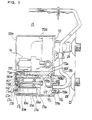
- FIG. 1 is a perspective view of the interior of a toilet room having many washbowls each equipped with an automatic faucet according to the present invention
- FIG. 2 is a perspective view of the washbowl
- FIG. 3 is s a sectional side view showing the entire consrtruction of the automatic faucet
- FIG. 4 is a sectional side view of a valve control box taken on line I - I of FIG. 3
- FIG.5 is a sectional plan view of the valve control box taken on line II ⁇ II of FIG. 3
- FIG. 6 is an enlarged sectional plan view of fitting portion of a control device to a drive portion unit
- FIG. 7 is an enlarged sectional side view taken on line II ⁇ II of FIG. 6;
- FIG. 1 is a perspective view of the interior of a toilet room having many washbowls each equipped with an automatic faucet according to the present invention
- FIG. 2 is a perspective view of the washbowl
- FIG. 3 is s a sectional side view showing the entire consrtruction of the automatic
- FIG. 8 is an enlarged sectional plan view of the interior of the control device;
- FIG. 9 is an arrowed side view taken along the line IV ⁇ IV of FIG. 8;
- FIGS. 10 to 12 are cross-sectional views of a spout body taken on lines V ⁇ V, VI ⁇ VI and VII ⁇ VII, respectively, of FIG. 3;
- FIG. 13 is a view for explaining the fitting state of a manual sensor at the extreme end of the spout body;
- FIG. 14 is a cross-sectional view of a manual sensor taken on line VII ⁇ VII of FIG. 13;
- FIG. 15 is an exploded perspective view of a locking construction of the spout body;
- FIG. 16 to 18 are explanatory views, respectively, of a work for locking a spout body;
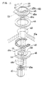
- FIG. 19 is an explanatory view of an operating portion of a thermostat type mixing valve
- FIG. 20 is an exploded perspective view of the same
- FIG. 21 is a side view showing the entire construction of an automatic faucet according to another embodiment
- FIG. 22 is a plan view of the same partly sectioned
- FIG. 23 is a front view of the same partly sectioned
- FIG. 24 is a front view of essentioal parts of the same
- FIG. 25 is a view for explaining the fitting state of a manual sensor at the extreme end of the spout
- FIG. 26 is a cross-sectional view of a manual sensor taken on line IX ⁇ IX of FIG. 25
- FIG. 27 is an explanatory view of the internal construction of an electromagnetic closing valve
- FIGS. 28 and 29 are sectional views taken on lines X ⁇ X and XI-XI, respectively, of FIG. 21.
- FIG. 1 shows the interior of a toilet room in which many washbowls B are mounted on a cabinet C, each washbowl B being equipped with an automatic faucet A according to the present invention, as shown in the drawings.
- FIGS. 2 and 3 show the entire construction of the washbowl B and the automatic faucet A. As shown in the drawings, the washbowl 3 is fitted in and secured to a fitting groove cut in a counter forming an upper portion of the cabinet C.
- a spout 11 is fixedly mounted on a mounting surface 10a in the inner part of a bowl 10 of the washbowl B, and a drive portion unit 13 connected in communication to the spout 11 through a hot water supply pipe 12 is disposed at the lower part of the bowl 10.
- the drive portion unit 13 integrally encases therein an electromagnetic closing valve 14 connected in communication to an upstream side of the hot water supply pipe 12, a thermostat type mixing valve 15 connected in communication to the electromagnetic closing valve 14, a control device 16 for controlling the operation of the electromagnetic closing valve 14 and various sensors described later, and a power supply device 17.
- openings on the other side of a pipe 18 on the hot water side and a pipe 19 on the cold water side of which one end is embedded in and supported on the wall 0 are connected in communication to a hot water opening and a cold water opening of the thermostat type mixing valve 15.
- Water stop valves are housed in the base portions of the pipe 18 on the hot water side and the pipe 19 on the water side, respectivel y.
- the drive portion unit 13 is constituted by removably connecting a control device 16 in the shape of a small rectangular box and a power supply device 17 with a rectangular space 70 formed at one side corner at the upper portion of a body case 13a in the shape of a rectangular box.
- the body case 13a consists of a base plate 71 on the wall side which is thick and substantially in the shape of a rectangular plate and a thin box-like cover 72 removably connected to the base plate 71 on the wall side by means of a connecting bolt 71m.
- the box-like cover 72 is formed from a front plate 72a, a top plate 72b, a bottom plate 72c and left and right side plates 72d and 72e.
- the box-like cover 72 is provided with an opening 72f for connecting the control device at a location at the upper portion of the right side plate 72e and connected to the control device 16.
- a thermostat type mixing valve 15 In the central portion within the body case 13a, there are disoosed a thermostat type mixing valve 15, a water stop valve 61 and an electromagnetic closing valve 14 in that order vertically from bottom to top on a hot water supply flow path 40.
- a cylindrical body 15a encases a movable (forward and backward) valve stem 15b for adjusting a valve opening degree according to a temperature of mixed hot water whereby the temperature of the mixed hot water can be automatically adjusted to a set temperature.
- the cylindrical body 15a of the thermostat type mixing valve 15 is connected to a pair of bended pipes 73 and 74 which once extend laterally as shown in FIG. 4 and thereafter extend through a base plate 71 on the wall side of the body case 13a and project outside as shown in FIG. 3.
- the bended pipes 73 and 74 are removably connected to the pipe 18 on the hot water side and the pipe 19 on the water side by annular connecting fittings 73a and 74a, respectively, as shown in FIG. 3.
- the water stop valve 61 consists of a valve plate 61b for turning off an opening 61a provided in the midst of the hot water supply flow path 40 and a threaded rod 61c for moving the valve plate 61b forward and backward, which is used to fix trouble which may occur on the downstream side from the electromagnetic closing valve 14.
- the electromagnetic closing valve 14 used in the present embodiment comprises a diaphragm valve which is operated by a latching solenoid. By application or release of voltage, the electromagnetic closing valve 14 can cause a plunger 14c thereof to be moved forward and backward, a valve body 14a formed from a diaphragm to come into contact with or to move away from a valve seat 14b and an opening 14d remotely provided at the upper portion of the hot water supply flow path 40 to be opened and closed.
- the hot water supply flow path 40 provided interiorly of the drive portion unit 13 will be described hereinafter.
- the flow path 40 comprises a first hot water supply internal pipe 75 connected in communication to the thermostat type mixing valve 15 and the water stop valve 61, a second hot water supply internal pipe 76 connected in communication to the water stop valve 61 and the electromagnetic closing valve 14, and a third hot water supply internal pipe 77 connected in communication to the electromagnetic closing valve 14 and the hot water supply pipe 12.
- the drive portion unit 13 is substantially supported in a cantilever fashion by the pipe 18 on the hot water side and the pipe 19 on the water side embedded in and supported on the wall 0 through the base plate 71 on the wall side of the body case 13a, the hot water supply flow path 40 and the bended pipes 73 and 74.
- the drive portion unit 13 can be easily removed from and connected to the pipe 18 on the hot water side and the pipe 19 on the water side by loosening and tightening annular connecting fittings 73a and 74a shown in FIG. 3.
- the body case 13a can separete the base plate 71 on the wall side and the box-like cover 72.
- the execution and maintenance of the drive portion unit 13 can be materially improved.
- the drive portion unit 13 integrally encases not only the electromagnetic valve 14 but also the thermostat type mixing valve 15 and the water stop valve 61, a so-called drive portion for the automatic faucet A can be formed into a compact shape and the external appearance thereof can be also improved.
- a dew drop preventing weir plate 72h is projected on the peripheral edge of a pipe leading opening 72g provided in a top plate 72b of the box-like cover 72, and only a portion in communication with the base plate 71 on the wall side of the weir plate 72h is cut to form an outflow opening 72i.
- control device 16 The construction of the control device 16 will be described with reference to FIGS. 4 to 9.
- the base plate 71 on the wal l side of the drive portion unit 13 is in the shape of an L-letter as viewed in plan, a part of which is extended into a control device connecting opening 72f of the box-like cover 72 to form a thick-wall partitioning wall 71a.
- the partitioning wall 71a is integrally formed with a rectangular annular projection 71b over the entire peripheral edge of the control device mounting side.
- a contact 71d for an electromagnetic closing valve formed from a conductive plate which is thin and has an elasticity is secured to the side on the control device side by connecting screws 71c, as shown in FIGS. 5, 6, and
- One end of a lead wire 71f for an electromagnetic closing valve is connected to the contact 71d for an electromagnetic closing valve, and the other end of the lead wire 71f is connected to the electromagnetic closing valve 14 through a connection opening 71e opened to the partitioning wall 71a.
- Reference numeral 71g designates a seal cap provided within the connection opening 71e.
- control device protective cover 16a forming an external portion of the control device 16 has a rectangular box shape, the partitioning wall 71a side of which is opened, and as shown in FIGS 5, 6 and 7, an annular opening 16b on the partitioning wall side is removably fitted and engaged with a rectangular annular projection 71b of the partitioning wall 71a.
- a packing 80 such as an 0-ring is fitted in said fitting and engaging surface to secure water-tightness so as to prevent entry of water or the like into the drive portion unit 13 from outside.
- reference numerals 80a and 80b designate a fixing screw and a fixing bolt provided to positively retain the aforesaid fitting and engagement.
- control device 16 and the power supply device 17 integral therewith can be easily and rapidly mounted on or disengaged from the drive portion unit 13 to materially improve the execution and maintenance.
- connection portion between the control device 16 and the drive portion unit 13 can be sufficiently secured, it is possible to positively prevent entry of water into the control device 16 and the power supply device 17, thus preventing trouble.
- a bracket 16c for mounting a control base plate is disposed at a position close to the partitioning wall 71a, and a control base plate 16d having a control portion 81 mounted on the upper surface thereof is mounted on the bracket 16c.
- control base plate 16d On one side end of the control base plate 16d is mounted an L-shaped contact 16e for an electromagnetic closing valve on the control device side, and when the control device protective cover 16a is removably fitted in and engaged with the rectangular annular projection contact 16e can contact with the contact 71d for an electromagnetic closing valve to electrically connect the control portion 81 with the electromagnetic closing valve 14.
- control portion 81 can be connected to the electromagnetic closing valve 14 merely by mounting the control device 16 to the drive portion unit 13 without requiring any separate connecting work. Therefore, the execution and maintenance of the drive portion unit 13 can be materially improved.
- the other end of a sensor cord 37 with one end connected to a manual sensor 24 is connected with a terminal 16f provided on the other end of the control base plate 16d.
- a detection output can be positively sent from the manual sensor 24 to the control portion 81 by the sensor cord 37 to drive the electromagnetic closing valve 14.
- a seal ring 71i and a lid 71j are mounted within a sensor cord inserting opening 71h provided in the base plate 71 on the wall side, the seal ring 71i and the lid 71j being tightened by a tightening nut 71k.
- a dry cell case 17a composed of a flat plate 17a-1 and an L-shaped plate 17a-2 is disposed approximately parallelly with the bracket 16c for mounting a control base plate within the control device protective cover 16a.
- the dry cell case 17a is interiorly formed with a dry cell storing space 17b, on one end of which is provided an opening 17c for mounting a dry cell and on the other end of which is provided an opening 17f for guiding connection of contact for connecting both poles of the dry cell 17d stored in the dry cell storing space 17b to a dry cell contact 17e to be described hereinafter.
- the dry cell contact 17e is composed of a conductive plate which is thin and has an elasticity, as shown in FIGS. 8 and a base of which is secured to the inside on one end side of the bracket 16c for mounting a control base plate by means of a connecting pin 17g.
- an end of the dry cell contact 17e is disposed facing to the opening 17f for guiding connection of contact of the dry cell case 17a, and when the dry cell 17d is stored into the dry cell storing space 17b, the said end automatically comes into contact with both poles of the dry cell 17d to render them conductive.
- an extension 17h is provided on the base end of the dry cell contact 17e, and the end of the extension 17h is connected to a conduction guide plate 17i provided on the control base plate 16d.
- the dry cell case 17a, the bracket 16c for mounting a control base plate and the control base plate 16d are integrally formed in the state where the contact 16e for an electromagnetic closing valve and the dry cell contact 17e are assembled, which, in that form, can be incorporated into the control device protective cover 16a.
- control device 16 and the power supply device 17 can be improved.
- a rectangular opening 17j in communication with the dry cell storing space 17b is provided frontwardly of the control device protective cover 16a, and a lid 171 having a circular dry cell mounting opening 17k in the central portion thereof is removably mounted on the rectangular opening 17j by means of a connecting bolt 17m.
- a dry cell fixing plate 17n is integrally connected to the upper portion at the rear end of the dry cell 17d stored into the dry cell case 17a through the opening 17k for mounting the dry cell, the plate 17n being removably connected to the lid 171 by means of a fixing bolt 17o.
- replacement of the dry cell 17d can be easily accomplished merely by loosening the fixing bolt 17o to remove it together with the dry cell fixing plate 17n, mounting the dry cell fixing plate 17a on the rear portion of a new dry cell 17d, thereafter storing the dry cell 17d into the dry cell storing space 17b through the opening 17k for mounting a dry cell, and connecting the dry cell fixing plate 17n to the lid 171 by the fixing bolt 17o.
- a power-off display lamp 82 such as LED is connected to one side of the control base plate 16d, and a transparent window 83 for facilitating vision from the outside is provided on the front wall of the control device protective cover 16a ahead of the display lamp 82.
- a comparator or the like is used to detect it so that the power-off display lamp 82 formed from LED or the like can be quickly flickered to quickly inform a maintenance person or a user or time for replacement of the dry cell 17d.
- the machine in the system is temporarily stopped to flicker the power-off display lamp 82 formed from LED or the like so that a maintenance person or a user may pay attention thereto.
- the power supply device 17 uses the dry cell 17d so that a low voltage is supplied to the electromagnetic closing valve 14 or the manual sensor 24 therefrom. Therefore, trouble such as an electric shock can be positively prevented.
- a feature of the spout 11 substantially resides in the construction in which a protective cover 22 for a sensor or the like formed of a synthetic resin material such as plastics is removably mounted on the inside of a spout body 21 made of casting having a discharge water flow path 20 formed integral with the wall, and a fitting space S for the sensor or the like is formed between the spout body 21 and the protective cover 22 for the sensor or the like to store a manual sensor 24 or the like therein, as shown in FIG. 3.
- the construction of the spout body 21 will be first described. As shown in FIGS. 2 and 3, the spout body 21 has its base end side secured to a place surface 10 at the inner part of a washbowl 10, and an extreme end thereof directed frontwardly of the bowl 10 and extended in an upwardly inclined state.
- the spout body 21 is formed with a lengthy space 25 having an approximately semicircular section over all 'ength thereof, and a part of the lengthy space 25 is divided by a part of an upper wall 21a and an L-shaped partitioning wall 21b to form a discharge water flow path 20.
- the lengthy space 25 provided interiorly of the spout body 21 can cooperate with the protective cover 22 for the sensor or the like described later to form a fitting space S for the sensor or the like previously mentioned.
- a sensor cord storing space 29 extending to the base end of the spout body 21, as shown in FIGS. 3 and 10.
- the fitting space S for the sensor or the like is constituted by the sensor fitting space 28 and the sensor cord storing space 29.
- the extreme end of the L-shaped partitioning wall 21b forming the discharge water flow path 20 is bended downwardly at the rear position spaced from the crossing partitioning wall 27 to cooperate with the crossing partitioning wall 27 to form a cylindrical opening 30, as shown in FIG. 3.
- a water discharge cap 30a is removably threadedly mounted within the cylindrical opening 30.
- the construction of the base portion of the spout body 21 will be described.
- the aforesaid base portion is composed of a semicircular rear wall 21c and a pair of frontwardly extending walls 21d and 21d frontwardly extending parallel with each other from the both front ends of the rear wall 21c, as shown in FIGS. 3 and 11.
- the base portion of the spout body 21 cooperate with a base portion 22a of the protective cover 22 for the sensor or the like to form a cylindrical spout fitting portion, as shown in FIG. 11.
- the protective cover 22 is s formed from a thin lengthy Flat plate formed of a synthetic resin material and removably mounted on the inside of the spout body 21 to thereby form a spout 11, as shown in FIG. 3.
- the mounting of the protective cover 22 for the sensor or the like is carried out by threadedly connecting the extreme end and the central portion of the protective cover 22 for the sensor or the like to a boss portion 33 at the extreme end and a central boss portion 34 of the spout body 21 by connecting screws 31 and 32, respectively, as shown in FIG. 3.
- the protective cover 22 for the sensor or the like is provided in its extreme end with a through-hole 35 for the sensor for exposing a sensor block 24a of the manual sensor 24 to outside and at a position spaced rearwardly of the through-hole 35 for the sensor with a cylindrical opening with the water discharge cap 30a threadedly mounted thereon, that is, a water discharging opening 36 for exposing a water discharge port 30 to outside.
- the base portion 22a of the protective cover 22 for the sensor or the like is in the form of a flat plate, which cooperates with the rear wall 21c of the spout body 21 as previously mentioned to form a water-tight cylindrical spout fitting portion.
- the protective cover 22 for the sensor or the like is connected to the spout body 21 in a water-tight state over the overall length thereof.
- the fitting space S for the sensor or the like is not in a completely water-tight state, it is designed so that a weir 100 is provided, and moved-in water is escaped from both sides of the protective cover 22 or from a clearance between the base portion 22a of the protective cover For the sensor or the like and an upper portion defining ring 45 described later.
- a sensor mounting space 38 with a through-hole 35 for the sensor opened to the lower surface thereof is formed in the upper surface at the extreme end of the protective cover 22 for the sensor or the 1 i ke.
- a sensor block 24a, a sensor base plate 24b for connecting one end of the sensor cord 37 described later and a transparent plate 24c are integrally molded, by resin mold agent 24d such as expoxy resin, within a sealed box in the shape of a rectangular box composed of a rectangular cylindrical sensor case 24e and a case cover 24f.
- the sensor block 24a is interiorly provided with sensor element fitting holes 24g and 24h in a spaced relation, and a projection element 24i formed from a phototransistor the base end of which is connected to the sensor base 24b and a light receiving element 24j formed from a photodiode are mounted within the fitting holes 24g and 24h.
- the manual sensor 24 When infrared ray emitted from the projection element 24i and reflected by the hand is received by the light receiving element 24j, the manual sensor 24 generates a detection output to send an output signal to the control device 16, to drive the electromagnetic closeing valve 14 and to automatically discharge hot water from the discharge water cap 30a.
- the manual sensor 24 and the sensor cord 37 connected to the sensor 24 are substantially disposed within a resin mold construction, it is possible to positively prevent entry of water to the sensor block 24a and the sensor base plate 24b and erroneous operation of the manual sensor 24.
- the manual sensor 24 Since the sensor direction D 1 of the manual sensor 24 is made parallel with the discharge water direction D 2 of the discharge water port 30, the manual sensor 24 will not detect a discharge water flow but the erroneous operation can be positively prevented, as shown in FIG. 3.
- the manual sensor 24 is provided on the extreme end side distanced from the discharge water port 30, when hands reach out toward the discharge water port 30, the manual sensor 24 first detects it and actuates, after which water is turned on quickly. On the other hand, after the hands have been completely withdrawn from the discharge water port 30 after cleaning, the manual sensor 24 generates an off-output to quickly stop the water discharge.
- the using convenience of the automatic faucet A can be materially improved.
- one end of a plurality of sensor cords 37 is connected to the upper surface of the sensor base plate 24b, and the other end oF the sensor cord 37 extends into the sensor cord storing space 29 formed between the spout body 21 and the protective cover 22 for the sensor or the like through a sensor cord leading path 2dk provided interiorly of the case cover 21f and thereafter is connected to the control device 16 through the cylindrical metal Fitting portion of the automatic faucet A.
- a rubber bushing 24m is introduced under pressure against the resilient force thereof into a sensor cord leading end 241 of the sensor cord leading path 24k, and one end of the sensor cord 37 is embeded into a resin mold agent 24d.
- the cooperation between the aforesaid resin mold construction and the rubber bushing 24m can improve the contactness between the sensor cord 37 and the resin mold agent 24d, materially improve the water resistance of the manual sensor 24 and more positively prevent the erroneous operation of the manual sensor 24.
- the sensor case 24e has a support bracket 24n extended rearwardly from the rear waill as shown in FIG. 9, the bracket 24n being secured in a cantilever fashion to the protective cover 22 For the sensor or the like by means of a fixing bolt 240.
- the plurality of sensor cords 37 are extended into the sensor cord storing space 29 and thereafter encircled integrally by a sensor cord protective cable 39, the protective cable 39 being connected to the control device 16 through the base portion of the spout 11, as shown in FIG. 3.
- the sensor cord protective cable 39 has a water return ring 39a mounted at the rear of the sensor cord storing space 29, as shown in FIG. 3.
- a water return ring 39a mounted at the rear of the sensor cord storing space 29, as shown in FIG. 3.
- the sensor cord protective cable 39 is removably supported on a censor cord fitting device 39d secured by means of a connecting screw 39c to the upper surface of a support post 39b stood upright in the central portion of the protective cover 22 for the sensor or the like. Accordingly, the sensor protective cable 39 can be positioned considerably above the upper surface of the protective cover 22.For the sensor or the like along which scattered water flows, and in view of this, the water resistance with respect to the sensor cord 37 can be achieved.
- hot water supply pipe construction will be described in which hot water is supplied from a hot water supply flow path 40 formed in the drive portion unit 13 to a discharge water flow path 20 Formed in the spout body 21 of the spout 11.
- the spout 11 is provided in its base end with a cylindrical threaded portion 41a connected in communication to the lower part of the discharge water flow path 20.
- a discharge water flow path connecting pipe 41 is threadedly mounted on the cylindrical threaded portion 41, and the lower end of the connecting pipe 41 extends through a spout fitting opening 42 provided at the place surface 10a in the inner part of the bowl 10 and at a position immediately below the base end of the spout 11 to be extended downwardly.
- the lower end of the discharge water flow path connecting pipe 11 is connected to the side end at downstream of the hot water supply pipe 12 in a water-tight state by use of a union 43, whereas the side end at upstream of the hot water supply pipe 12 is connected to an opening at downstream of the hot water supply flow path 40 formed within the drive portion unit 13.
- the mixed hot water can be supplied quickly to the discharge water flow path 20 through the hot water supply flow path 40 - the hot water supply pipe 12 -- the discharge water flow path connecting pipe 41.
- the spout fixing construction is substantially composed of an upper seal ring 44 and an upper defining ring 45 provided in a superposed state above the spout Fitting opening 42 provided in the place surface 10a in the inner part of the bowl 10, a shake proof washer 47 provided in a superposed state below the spout fitting opening 42, a lower fitting washer 48, and a fastening nut 49.
- the upper defining ring 45 is composed of an annular collar 45a provided in the central outer peripheral edge thereof, a spout fitting portion 45b and a washbowl fitting portion 45c formed above and below, respectively, thereof, as shown in FIG. 15.
- the spout fitting portion 45b is fitted to the base portion of the spout 11 and is integrally connected by a connecting bolt 50 as shown in FIG. 7.
- the bowl fitting portion 45c is fitted into the spout fitting opening 42 provided in the bowl 10 to positively locating a fitting position of the spout 11.
- the upper defining ring 45 is provided with a heart-shaped irregular through-hole 52 through which extend the discharge water Flow path connecting pipe 41, the sensor cord protective cable 39 and a guide pin 51 described later.
- a through hole 53 for a pop-up type drain plug operating rod is provided at a position adjacent to the through-hole 52.
- the lower fitting washer 48 is s composed of an upper spread collar 48a having a horse-shoe shape, and a lower cylindrical portion 48b integrally connected at an eccentric position from the center on the inside of the collar 48a.
- the lower fitting washer 48 is provided in its eccentric position from the center with a large-diameter through-hole 54 through which is inserted the discharge water flow path connecting pipe 41 and a small-diameter through-hole 55 through which is inserted a guide pin 51 described later, as shown in FIGS. 12 and 15.
- the lower fitting washer d8 is Further provided in the peripheral edge of the upper spread collar 48a with a circular cutaway space 56 one end of which is opened to outside, as shown in FIG. 15, and the sensor cord 37 and a pop-up type drain plug operating rod 57 are inserted into the space 56, as shown in FIG. 3.
- the upper defining ring d5 is fitted, connected and fixed to the base end of the spout body 11 with the sensor and cord protective cable 39
- the discharge water flow path connecting pipe 41 and the upper end of the guide pin 51 are threadedly fitted to the cylindrical threaded portions 14a (FIG. 3) and 41b (FIG. 16) provided in the base end of the spout body 11.
- the discharge water flow path connecting pipe 41 is made to extend through the spout fitting opening 42 provided in the bowl 10, and the lower fitting portion 45c of the upper defining ring d5 is fitted into the spout Fitting opening 42 through the upper seal ring 44.
- the shake proof washer 47, the lower fitting washer 48 and the Fastening nut 49 are Fitted in order into the outer peripheral surface of the discharge water flow path connecting pipe 41 from the lower end of the latter, and the guide pin 51 is made to extend through the pin insert hole 55 provided in the lower fitting washer 48.
- the fastening nut 49 is turned to engage an internal threaded hole 49a wiht an external threaded portion 58 provided in the outer peripheral surface in the midst of the discharge water flow path connecting pipe 41, as shown in FIG. 16.
- the upper defining ring 45 is powerfully secured to the bowl 10, and the spout 11 integral with the upper defining ring 45 is also powerfully secured to the bowl 10.
- the lower fitting washer 48 has a horse-shoe shape and is provided with the circular cutaway space 56 one end of which is opened, as shown in FIGS. 8 and 11, the sensor and cord protective cable 39 can be fitted in and engaged with the circular cutaway space 56 from the outer side, and the spout fixing work can be very easily carried out despite the presence of the protective cable 39.
- the cutaway space 56 provided in the lower fitting washer 48 can be positioned in a given direction at which the sensor cord 37 is easily drawn out, it is possible to prevent the sensor cord 37 from being twisted, and it is possible to easily carry out a work for drawing the sensor cord 37.
- the relative positional relationship between the external threaded portion 58 provided in the outer peripheral surface of the discharge water flow path connecting pipe 41 and the washer guiding guide pin 51 is set so as not to threadedly engage with the internal threaded hole 49a of the fastening nut 49 till the washer guiding guide pin 51 is inserted into the pin insert hole 55. Therefore, it is possible to positively prevent occurrence of erroneous execution to position the cutaway space 56 to an accurate sensor cord drawing position.
- the pin insert hole 55 provided in the lower fitting washer 48 has a length enough to insert the washer guiding guide pin 51, even if the spout fitting plate such as the mounting surface 10a in the inner part of the bowl 10 is thin as shown in FIG. 18, it is possible to positively guide vertically moving operation of the lower fitting washer 48 to firmly fix the spout 11 to the discharge water fitting plate, and prevent trouble such as a breakage of the sensor cord 37.
- the lower end of the dicharge water flow path connecting pipe 41 is connected in a water-tight state to the side end at upstream of the hot water supply pipe 12 by use of a box nut 43.
- the pop-up type drain plug operating rod 57 is s extended downward through the small-diameter through-hole 59 provided in the base of the metal 11, the through-hole 53 for the pop-up type drain plug operating rod provided in the upper defining ring 45, the upper seal ring 44, the discharge water metal fitting opening 42, the shake proof washer 47, and the circular cutaway space 56 of the lower fitting washer 48, and the extended end thereof is operatively connected to a pop-up drain plug not shown.
- the dry cell 17d is mounted on the dry cell case 17a whereby a low voltage is supplied to the electromagnetic closing valve 14 and the munual sensor 24 to render the automatic faucet A initial state.
- the manual sensor 24 issues an ON-output.
- the control devide 16 sends a drive signal to the electromagnetic closing walve 14 on the basis of the on-output to drive the electromagnetic closing valve 14 whereby the plunger 14c is moved backward and the walve body 14a is moved away from the valve seat 14b to open the valve, as shown in FIG. 3.
- the mixed hot water at a moderate temperature adjusted by the theremostat type mixing walve 15 is supplied to the discharge wate flow path 20 through the hot water supply flow path 40 ⁇ the hot water supply pipe 12 ⁇ the discharge water flow path connecting pipe 41, after which the hot water is discahrged out of the discahrge water cap 30a so that hands can be cleaned.
- the manual sensor 24 After completion of cleaning, when a user draws his hand, the manual sensor 24 does not detect the hands any longer. It sends an OFF-output to the control device 16.
- the control devide 16 causes the plunger 14c of the electromagnetic closing valve 14 to move forward on the basis of the OFF-output to bring the valve body 14a into contact with the valve seat 14b to open the valve.
- the elctromagnetic closing vavle 14 is driven to open or close the valve, after which even if power is not supplied, opening or closing state of the valve can be self-maintained to save power.
- the water resistance of the electromagnetic closling valve 14 and the control portion 81 can be attained by mounting them in the drive portion unit 13 and the control device protective cover 16, and thereafter fitting and connecting the control device protective cover 16a to the drive portion unit 13 in a water-tight state.
- a packing 80 such as an 0-ring is provided in the fitting portion to provide a complete water-tightness.
- the electromagnetic, closing valve 14 and the control portion 18 need not be independently water proof construction, the water proof construction becomes simple so that the number of parts can be reduced, the device can be manufactured at less cost, and the execution can be imoroved. Furthermore, the control device protective cover 16a can be removed from the drive portion unit 13 to facilitate the repairing work. Therefore, maintenance such as adjustment of sensing length of the manuai sensor 24 can be also improved.
- a how-to-use display plate 101 can be mounted on the surface of the discharge water metal 11 and on the front wall 26 of the metal main body 21 which attracts user's attention.
- a user of the automatic faucet A irrespective of an ordinary person as well as an infant and the old can easily and positively recognize the how-to-use displayed on the how-to-use display plate 101, which can be used easily and accurately.
- the mixing valve 15 is designed so that a temperature setting screw 15d is exposed to the front surface of a front panel 15f of the casing encasing therein the mixing valve 15, a collar ring 15 i is fitted into the temperature setting screw 15d from the outside, a cover ring 15j Formed with a projection 15k on the inner peripheral surface and a notch 15p extending from the surface to the inside is fitted on the outside of the collar ring 15i, the cover ring 15j is secured to the temperature setting screw 15d with interference of the temperature setting screw 15d and the projection 15k, and a part of the collar ring 15i is made visible from the outside through the notch 15p.
- a mark can be provided on the side of the cover ring 15j having a good appearance merely by providing the collar ring 15i and the cover ring 15j over the temperature setting screw 15d. Since the position of the notch 15p can be adjusted freely, the mark on the side of the temperature setting screw can be registered with the mark on the side of the front panel.
- reference numeral 15g denotes a screw insert hole, 15h, a circular groove for insertion of a tool such as a driver or a coin, 15m a mark of the front panel 15f of the drive portion unit 13, 15n a seal member, and 15o a spring for biasing a thermostat 15c in a direction of the valve seat 15e.
- a short-circluit plate 17r is attached to the upper surface in the inner oart of the flat plate 17a-1 so as to oppose to a contact portion 17q extended to the extreme end of a dry cell contact 17e.
- an abutment 17v placed in abutment with the inner end of the dry cell 17d and raised upward to release the contact between the short-circuit plate 17r and the dry cell contact 17e to prevent the dry cell 17d from being short-circuited.
- the contact protion 17q comes into contact with the short-circuit plate 17r to short-circuit + - of the contact 17 1 , 17 - to erase a charge of the control base plate 16d.
- a charge such as static electricity is prevented from being applied to IC or the like to prevent the IC or the like from being damaged.
- a dry cell drawing rod is provided on a lid of the dry cell case 17a encasing the dry cell 17d, and the contact portion is extended to an input terminal of power supply of the control base plate 16d of the control device 16 so that when the dry cell 17d is drawn, the contact portion comes into contact with the dry cell drawing rod to erase the charge of the control device 16.
- both poles of the input terminal of the power source of the control base plate 16d of the control device 16 are made to be short-circuited to erase the charge of the control device 16.
- the charge such as static electricity can be prevented from being applied to prevent the IC or the like from being damaged.
- a spout body 111 is placed in a fixed state on a mounting surface 110a in the inner part of a bowl 110 of a washbowl B.
- the spout body 111 is interiorly provided with a hot and cold water mixing valve 115 of which upstream is connected in communication to a pipe 118 on the hot water supply side and a pipe 119 on the water supply side, an electromagnetic closing valve 114 having its upstream connected in communication to the mixing valve 115 and its downstream connected in communication to a cylindrical opening 130 formed with a discharge port through a hot water supply pipe 12, a controller 116 for controlling the drive of at least the electromagnetic closing valve 114, a manual sensor 124 for sending an output signal to the controller 116, and a battery type power source 117 for feeding power to the electromagnetic closing valve 114, the controller 116 and the manual sensor 124.
- the electromagnetic closing valve 114 when the electromagnetic closing valve 114 is driven and opened, the mixed hot water at a moderate temperature can be supplied from the cylindrical opening 130 provided at extreme end of the spout body 111 into the washbowl B through the pipe 118 on the hot water supply side and the pipe 119 on the cold water supply side ⁇ the mixing valve 115 ⁇ the electromagnetic closing valve 114 ⁇ the hot water supply pipe 112.
- the spout 111 is interiorly integrally provided with the hot water and cold water mixing valve 114, the controller 116 for controlling the driving of the electromagnetic closing valve 114, the manual sensor 124 for sending an output signal to the controller 116, and the battery type power source 117 for feeding power to the electromagnetic closing valve 114, the controller 116 and the manual sensor 124. Therefore, the automatic faucet A, irrespective of existing installation or new installation, can be installed merely by ordinary waterworks without necessity of complicated electric wiring works to reduce fitting and installation costs.
- the spout 111 interiorly integrally provided with the hot water and cold water mixing valve 115, the electromagnetic closing valve 114, the manual sensor 124 for sending an output signal to the controller 116, and the battery type power source 117 for feeding power to the electromagnetic closing valve 114, the controller 116 and the manual sensor 124. Therefore, a space for a toilet room or the like can be utilized at maximum.
- the spout 111 is substantially foniied in a manner such that as shown in FIGS. 21, 28 and 29, a protective cover 122 for a controller or the like formed of synthetic resin material such as plastics i removably mounted on the lower surface of a spout 121 made of casting having a U- shaped section with a lower portion opened.
- the spout 111 is interiorly formed with a fitting space S for a controller or the like to integrally store therein the electromagnetic closing valve 114, the mixing valve 115, the manual sensor 124 and the like other than the controller 116.
- the spout 121 has the base end secured to the mounting surface 110a in the inner part of the bowl 110 and the extreme end extended in an upwardly inclined state while being bended in a linear state over two stages directed frontwardly of the bowl 110.
- the spout 121 has its extreme end alone formed to have an approximately semicircular section as shown in FIG. 23, said extreme end being formed with a front wall 126.
- a how-to use display plate on which a how-to-use of the automatic faucet A is described is mounted on the outer surface of the front wall 126.
- a crossing diaphragm block 127 is mounted on the inner surface of the spout body 121 by means of a connecting bolt 127a. Between the front wall 126 and the crossing diaphragm block 127, the manual sensor 124 is stored within a sensor installing space 128.
- an accommodating space S for a controller or the like extending to the base end of the spout body 121 as shown in FIGS. 21, 28 and 29.
- crossing diaphragm block 127 is interiorly formed with an L-shaped flow path 127b, one end of which is connected in communication to the hot water supply pipe 112.
- the other end of the L-shaped flow path 127b is connected in communication to a cylindrical opening 130 provided at the rear of a sensor supporting plate 124r which will be described later.
- a discharge water cap 130a is removably threadedly mounted within the cylindrical opening 130.
- the base portion 121a cooperates with a base portion 122a of the protective cover 122 for the controller or the like to form a cylindrical spout fitting portion, as shown in FIG. 21.
- the protective cover 122 for the controller or the like will be described.
- the protective cover 122 is formed from a thin lengthy flat plate formed of synthetic resin material, and can be removably mounted on the inside of the spout body 121 to thereby form a spout 111.
- the mounting of the protective cover 122 for the controller or the like is carried out, as shown in FIG. 21, by threadedly connecting the upper portion of the protective cover 122 for the controller or the like to a rib 132 provided on the inner surface of the spout body 121 and inserting a lower end 122b of the protective cover 122 into an insert hole 145d provided in an anuular collar 145a of an upper defining ring 145 which will be described later.
- the protective cover 122 for the controller or the like is connected in a water-tight state over the full length to the spout body 121.
- a manual sensor 124 disposed in the fitting space 3 for the controller or the like formed between the spout body 121 and the protective cover 122 for the controller or the like and a sensor cord 137 for connecting the manual sensor 124 and the controller 116 will be described with reference to FIG. 21.
- a sensor support plate 124r is mounted between the upper end 122b of the protective cover 122 for the controller or the like and the extreme end 121b of the spout body 121, the sensor support plate 124r being formed in its lower surface with a sensor mounting space 138 with a through-hole 135 for a sensor opened.
- the sensor mounting space 138 is interiorly integrally molded with a sensor block 124a, a sensor base plate 124b and a transparent plate 124c by a resin mold agent 124d within a rectangular box formed from a rectangular sensor case 124e and a case cover 124f.
- sensor fitting holes 124g and 124h are provided in a spaced apart relation within the sensor block 124a, and a projection element 124i formed from a phototransistor with the base end connected to the sensor base plate 124b and a light receiving element 124j formed from a photodiode are fitted within the fitting holes 124g and 124h, respectively.
- the manual sensor 124 when infrared ray projected from the projection element 124i and reflected by hands is received by the light receiving element 124j, the manual sensor 124 generates a detection output to send an output signal to the controller 116.
- the electromagnetic closing valve 114 is then driven to automatically discharge hot water from the discharge water cap 130a.
- the sensor cord 137 For connecting the manual sensor 124 having the above-described construction to the controller 116 will be described.
- one end of a plurality of sensor cords 137 is connected to the upper surface of the sensor base plate 124b, and the other end of the sensor cord 137 is extended into the sensor cord storing space 129 formed between the spout body 121 and the protective cover 122 for the controller or the like through a sensor cord leading path 124k provided within the case cover 124f, after which the cord is connected to the controller 116 through the cylindrical spout fitting portion of the automatic faucet A.
- a bushing 124m made of rubber is pressed under pressure into a sensor cord leading end 1241 of the sensor cord leading path 124k, and one end of the sensor cord 137 is embedded into a resin mold agent 124d.
- the contactness between the sensor cord 137 and the resin mold agent 124d is improved, the water resistance of the manual sensor 124 can be materially improved, and the erroneous operation of the manual sensor 124 can be positively prevented.
- the sensor case 124e has a support bracket 124n extended rearwardly from the rear wall thereof, the bracket 124-n being secured in a cantilever state to the protective cover 122 for the controller or the like by means of a fixing bolt 124o.
- the plurality of sensor cords 137 are extended into the fitting space S for the controller or the like and thereafter connected to a base plate 116a of the controller 116 which will be described later, as shown in FIG. 21.
- hot water and cold water supply piping construction will be described with reference to FIG. 21, in which hot water and cold water are supplied from the pipe 118 on the hot water supply side and the pipe 119 on the cold water supply side into the hot water and cold water mixing valve 15 provided on the base portion of the spout body 121 of the spout 111.
- the mixing valve 115 is provided in the base end of the valve body block 115a with a pair of a hot water introducing hole 115b and a water introducing hole 115c, and the upper ends of the pipe 118 on the hot water supply side and the pipe 119 on the cold water supply side are inserted into and connected to both the introducing holes 115b and 115c, respectively.
- the lower ends of the pipe 118 on the hot water supply side and the pipe 119 on the cold water supply side extend through the spout opening 142 provided at the mounting surface 110a in the inner part of the bowl 110 and at a position immediately below the base end of the spout body 111, and are extended downwardly.
- the base end of the valve body block 115a is provided with an internal threaded hole 115d parallel with the hot water introducing hole 115b and the water introducing hole 115c, and the upper ends of the pipe 118 on the hot water supply side and the pipe 119 on the cold water supply side are inserted into and connected to the introducing holes 115b and 115c, respectively.
- hot water and cold water can be supplied from the pipe 118 on the hot water supply side and the pipe 119 on the cold water supply side to the mixing valve 115.
- the spout fixing construction is substantially designed so that an upper seal ring 144 and an upper defining ring 145 are disposed in a superposed state upwardly of the spout Fitting opening 142 provided in the place surface 110a in the inner part of the bowl 110, a shake proof washer 147, a lower fitting washer 148 and a fastening nut 149 are disposed in a superposed state below the spout fitting opening 142, and an external threaded rod 158 having an upper end threadedly mounted to the valve body block 115a of the nixing valve 115 is extended downward through the spout fitting opening 142 and a through-hole provided in the lower fitting washer 148, the fastening nut 149 being threadedly mounted on said extended end.
- the upper defining ring 145 comprises, as shown in FIG. 11, an annular collar 145a provided in the central peripheral edge thereof, and a spout body fitting portion 145b and a bowl fitting portion 145c formed above and below thereof.
- the spout body fitting portion 145b is fitted to the base portion of the spout 111 and integrally connected by a connecting bolt 150.
- a bowl fitting portion 145c is fitted to the spout opening 142 provided in the bowl 110 to positively perform locating of the fitting position of the spout fitting 111.
- the lower fitting washer 148 has a horse-shoe shape and is provided with a circular cutaway space 156 one end of which is opened, the pipe 118 on the hot water supply side and the pipe 119 on the water supply side can be fitted into and engaged with the circular cutaway space 156 from the external side, thus facilitating the spout fixing work.
- the hot water and cold water mixing valve 115 will be described. As shown in FIG. 21, in the mixing valve 115, the valve body block 115a is interiorly formed with a mixed hot water and cold water flow path 115f closeably communicated with the hot water introducing hole 115b and the cold water introducing hole 115c through a rotary valve body 115e.
- the rotary valve body 115e is provided with through-holes 115g and 115h with axes thereof deviated in a circumferential direction in an axially spaced relation, and a temperature adjusting handle 115k is connected to one end thereof by means of a connecting bolt 115j.
- the temperature adjusting handle 115k can be suitably rotated to thereby change a mixting ratio of hot water and cold water flowing into the mixing flow path 115f from the hot water introducing hole 115b and the water introducing hole 115c whereby the mixed hot water and cold water at a desired temperature can be obtained.
- the mixing valve 115 has been of the manual type, it is to be noted that the valve may comprise an automatic valve controlled by the controller 116 which will be described later.
- the electromagnetic closing valve 114 comprises a valve fitting block 114a integrally formed above the valve body block 115a of the mixing valve 115, a mixed hot water and cold water inlet path 114b and a mixed hot water and cold water outlet path 114c formed interiorly of the valve fitting block 114a, a pilot type diaphragm valve 114d disposed between the inlet path 114b and the outlet path 114c, and a latching solenoid 114e disposed above the diaphragm valve 114d.
- the latching solenoid 114e comprises, as shown in FIG. 27, a solenoid 114f, a plunger 114g disposed movably forward and backward in an axial direction within the solenoid 114f, and a permanent magnet 114h for latching.
- the diaphragm valve 114d is opened and closed to provide communication and cutoff between the inlet path 114b and the outlet path 114c.
- the battery type power source 117 As shown in FIGS. 21, 28 and 29, the power source 117 is constituted by a dry cell 117a removably mounted within a dry cell case 117b mounted on the inner surface in the midst of the protective cover 122 for the controller or the like.
- the controller 116 comprises a control base plate 116a disposed above the dry cell case 117b of the battery type power source 117, and controller body 116b provided above the control base plate 116a.
- a power-off display lamp 182 formed from an LED or the like is connected to one side of the control base plate 116a, and a transparent window 183 for facilitating viewing From outside is provided in a portion of the protective cover 122 for the controller ahead of the display lamp 182.
- Cord supporters 184 and 185 for supporting sensor cords 137 are provided on the upper surface of the dry cell case 117b of the battery type power source 117.
- the dry cell 117a is mounted on the dry cell case 117b whereby a low voltage is applied to the controller 116, the electromagnetic closing valve 114 and the manual sensor 124 to set the automatic faucet A in an initial state.
- the manual sensor 124 issues an ON-output, and the controller 116 sends a drive signal to the electromagnetic closing valve 114 in response to the ON-output to drive the electromagnetic closing valve 114 so that as shown in FIG. 3, thd plunger 114c is moved backward to open the pilot type diaphragm valve 114d.
- the mixed hot water and cold water at a moderate temperature adjusted by the mixing valve 114 can be discharged out of the discharge water cap 130a to clean hands.
- opening or closing state of valve can be self-maintained even if a power is not fed after the electromagnetic closing valve 114 has been once driven to be opened or closed, thus saving power.
- the automatic faucet according to the present invention has the merits as follows:
Landscapes
- Health & Medical Sciences (AREA)
- Life Sciences & Earth Sciences (AREA)
- Engineering & Computer Science (AREA)
- Hydrology & Water Resources (AREA)
- Public Health (AREA)
- Water Supply & Treatment (AREA)
- Domestic Plumbing Installations (AREA)
- Treatment Of Water By Ion Exchange (AREA)
- Temperature-Responsive Valves (AREA)
- Valve Housings (AREA)
- Magnetically Actuated Valves (AREA)
Abstract
Description
- The present invention relates to an automatic faucet capable of turning on and off the water on the basis of a sensor output from a manual sensor or the like.
- According to one form of an automatic faucet, in the past, a spout is formed of casting, interior of which is divided by a partitioning wall into two spaces to constitute a two-layer construction, one space being used as a discharge water flow path, the other space being used as a space in which a manual sensor such as an infrared sensor or a control unit is mounted, and a sensor cord or the like is provided.
- In such a spout as described above, behavior of a user's hand is detected by a manual sensor, while maintaining a compact shape thereof, and an electromagnetic closing valve or the like is driven on the basis of the detected output so that operation of turning on and off the water can be performed automatically. Since it is not necessary to operate the closing valve directly by the hand, the using mode can be materially improved.
- However, the spout cannot be disassembled because it is an integrally molded article formed of casting or the like. Therefore, a work for mounting a manual sensor or a control unit into the spout and a work for wiring a sensor cord to the sensor are cumbersome.
- As a result, the manufacturing cost for the automatic faucet becomes high, and when any trouble occurs, maintenance therefor cannot be carried out easily.
- It is an object of the present invention to provided an automatic faucet which can solve the aforementioned task.
- The present invention provides an automatic faucet characterized in that a protective cover for a sensor or the like is fittd in a superposed state and removably to the inner suface of spout body with a discharge water flow path formed integrally inside a wall so as to constitute a spout and a space for accommodating the sensor or the like is formed between the spout body and the protective cover for the sensor or the like.
- In this invention, the spout constituting the principal portion of the automatic faucet is formed by assembling substantially the mutually independent spout body having formed therein the discharge water flow path and the protective cover for the sensor or the like.
- Accordingly, the manual-sensor or the like can be fitted in advance on the protective cover for the sensor or the like, and the sensor cord can be wired in advance along the inner surface of the protective cover for the sensor or the like. Thereafter, the protective cover for the sensor or the like is mounted on the inside of the spout body whereby the spout of the automatic faucet can be easily assembled.
- Further, when any trouble occurs with the manual sensor or the like or the sensor cord is broken, the protective cover for the sensor or the like can be removed rapidly from the spout body and the broken portion can be fixed or replaced easily.
- FIG. 1 is a perspective view of the interior of a toilet room having many washbowls each equipped with an automatic faucet according to the present invention; FIG. 2 is a perspective view of the washbowl; FIG. 3 is s a sectional side view showing the entire consrtruction of the automatic faucet; FIG. 4 is a sectional side view of a valve control box taken on line I - I of FIG. 3; FIG.5 is a sectional plan view of the valve control box taken on line II―II of FIG. 3; FIG. 6 is an enlarged sectional plan view of fitting portion of a control device to a drive portion unit; FIG. 7 is an enlarged sectional side view taken on line II―II of FIG. 6; FIG. 8 is an enlarged sectional plan view of the interior of the control device; FIG. 9 is an arrowed side view taken along the line IV―IV of FIG. 8; FIGS. 10 to 12 are cross-sectional views of a spout body taken on lines V―V, VI―VI and VII―VII, respectively, of FIG. 3; FIG. 13 is a view for explaining the fitting state of a manual sensor at the extreme end of the spout body; FIG. 14 is a cross-sectional view of a manual sensor taken on line VII―VII of FIG. 13; FIG. 15 is an exploded perspective view of a locking construction of the spout body; FIG. 16 to 18 are explanatory views, respectively, of a work for locking a spout body; FIG. 19 is an explanatory view of an operating portion of a thermostat type mixing valve; FIG. 20 is an exploded perspective view of the same; FIG. 21 is a side view showing the entire construction of an automatic faucet according to another embodiment; FIG. 22 is a plan view of the same partly sectioned; FIG. 23 is a front view of the same partly sectioned; FIG. 24 is a front view of essentioal parts of the same; FIG. 25 is a view for explaining the fitting state of a manual sensor at the extreme end of the spout; FIG. 26 is a cross-sectional view of a manual sensor taken on line IX―IX of FIG. 25; FIG. 27 is an explanatory view of the internal construction of an electromagnetic closing valve; and FIGS. 28 and 29 are sectional views taken on lines X―X and XI-XI, respectively, of FIG. 21.
- The present invention will be described with reference to the accompanying drawings for describing the present invention in detail.
- FIG. 1 shows the interior of a toilet room in which many washbowls B are mounted on a cabinet C, each washbowl B being equipped with an automatic faucet A according to the present invention, as shown in the drawings.
- FIGS. 2 and 3 show the entire construction of the washbowl B and the automatic faucet A. As shown in the drawings, the washbowl 3 is fitted in and secured to a fitting groove cut in a counter forming an upper portion of the cabinet C.
- Next, the entire construction of the automatic faucet A will be described with reference to FIG. 3. A
spout 11 is fixedly mounted on amounting surface 10a in the inner part of abowl 10 of the washbowl B, and adrive portion unit 13 connected in communication to thespout 11 through a hotwater supply pipe 12 is disposed at the lower part of thebowl 10. - In the above-described construction, as shown in FIG. 3, the
drive portion unit 13 integrally encases therein anelectromagnetic closing valve 14 connected in communication to an upstream side of the hotwater supply pipe 12, a thermostattype mixing valve 15 connected in communication to theelectromagnetic closing valve 14, acontrol device 16 for controlling the operation of theelectromagnetic closing valve 14 and various sensors described later, and apower supply device 17. - As shown in FIGS. 4 and 5, openings on the other side of a
pipe 18 on the hot water side and apipe 19 on the cold water side of which one end is embedded in and supported on the wall 0 are connected in communication to a hot water opening and a cold water opening of the thermostattype mixing valve 15. - Water stop valves are housed in the base portions of the
pipe 18 on the hot water side and thepipe 19 on the water side, respectivel y. - In the construction as described above, when the
electromagnetic closing valve 14 is driven and opened, mixed hot water having a suitable temperature can be discharged from thespout 11 into the washbowl B through thepipe 18 on the hot water side, thepipe 19 on the water side - the thermostattype mixing valve 15 → theelectromagnetic colsing valve 14 → the hotwater supply pipe 12. - Parts constituting the aforesaid automatic faucet A will be described in detail hereinafter.
- First, the construction of the
drive portion unit 13 constituting the subject matter of the present invention will be described in detail with reference to FICS. 3 to 9. - Referring to FIGS. 3 to 5, particularly to FIG. 4, the
drive portion unit 13 is constituted by removably connecting acontrol device 16 in the shape of a small rectangular box and apower supply device 17 with arectangular space 70 formed at one side corner at the upper portion of abody case 13a in the shape of a rectangular box. - In the above-described construction, the
body case 13a consists of abase plate 71 on the wall side which is thick and substantially in the shape of a rectangular plate and a thin box-like cover 72 removably connected to thebase plate 71 on the wall side by means of a connectingbolt 71m. - The box-
like cover 72 is formed from afront plate 72a, atop plate 72b, abottom plate 72c and left andright side plates - The box-
like cover 72 is provided with an opening 72f for connecting the control device at a location at the upper portion of theright side plate 72e and connected to thecontrol device 16. - The internal construction of the
body case 13a will now be described. In the central portion within thebody case 13a, there are disoosed a thermostattype mixing valve 15, awater stop valve 61 and anelectromagnetic closing valve 14 in that order vertically from bottom to top on a hot watersupply flow path 40. - In the thermostat
type mixing valve 15, acylindrical body 15a encases a movable (forward and backward)valve stem 15b for adjusting a valve opening degree according to a temperature of mixed hot water whereby the temperature of the mixed hot water can be automatically adjusted to a set temperature. - The
cylindrical body 15a of the thermostattype mixing valve 15 is connected to a pair ofbended pipes base plate 71 on the wall side of thebody case 13a and project outside as shown in FIG. 3. Thebended pipes pipe 18 on the hot water side and thepipe 19 on the water side by annular connecting fittings 73a and 74a, respectively, as shown in FIG. 3. - The
water stop valve 61 consists of a valve plate 61b for turning off an opening 61a provided in the midst of the hot watersupply flow path 40 and a threadedrod 61c for moving the valve plate 61b forward and backward, which is used to fix trouble which may occur on the downstream side from theelectromagnetic closing valve 14. - The
electromagnetic closing valve 14 used in the present embodiment comprises a diaphragm valve which is operated by a latching solenoid. By application or release of voltage, theelectromagnetic closing valve 14 can cause aplunger 14c thereof to be moved forward and backward, a valve body 14a formed from a diaphragm to come into contact with or to move away from avalve seat 14b and an opening 14d remotely provided at the upper portion of the hot watersupply flow path 40 to be opened and closed. - The hot water
supply flow path 40 provided interiorly of thedrive portion unit 13 will be described hereinafter. Theflow path 40 comprises a first hot water supplyinternal pipe 75 connected in communication to the thermostattype mixing valve 15 and thewater stop valve 61, a second hot water supplyinternal pipe 76 connected in communication to thewater stop valve 61 and theelectromagnetic closing valve 14, and a third hot water supplyinternal pipe 77 connected in communication to theelectromagnetic closing valve 14 and the hotwater supply pipe 12. - In the above-mentioned construction of the hot water
supply flow path 40, as shown in FIG. 3, an upper portion of thebase plate 71 on the wall side of theboy case 13a is connected and secured to the third hot water supplyinternal pipe 77 by means of afastening screw 78, and a lower portion of thebase plate 71 on the wall side is supported by thebended pipes - Accordingly, in the present embodiment, the
drive portion unit 13 is substantially supported in a cantilever fashion by thepipe 18 on the hot water side and thepipe 19 on the water side embedded in and supported on the wall 0 through thebase plate 71 on the wall side of thebody case 13a, the hot watersupply flow path 40 and thebended pipes - The
drive portion unit 13 can be easily removed from and connected to thepipe 18 on the hot water side and thepipe 19 on the water side by loosening and tightening annular connecting fittings 73a and 74a shown in FIG. 3. - The
body case 13a can separete thebase plate 71 on the wall side and the box-like cover 72. - Accordingly, a work for installing the
drive portion unit 13 can be easily carried out. Even when any defect occurs in theelectromagnetic closing valve 14 within the drive portion unit 3, thewater stop valve 61, the thermostattype mixing valve 15, or thecontrol device 16 or thepower supply device 17, whole or part of thedrive portion unit 13 can be quickly and easily removed from thepipe 18 on the hot water side and thepipe 19 on the water side to quickly take adequate measure such as repair. After termination of the repair or the like, they can be quickly connected to thepipe 18 on the hot water side and thepipe 19 on the water side. - As described above, in the present embodiment, the execution and maintenance of the
drive portion unit 13 can be materially improved. - Furthermore, as described above, since the
drive portion unit 13 integrally encases not only theelectromagnetic valve 14 but also the thermostattype mixing valve 15 and thewater stop valve 61, a so-called drive portion for the automatic faucet A can be formed into a compact shape and the external appearance thereof can be also improved. - As shown in FIGS. 3 and a, in the present embodiment, a dew drop preventing
weir plate 72h is projected on the peripheral edge of a pipe leading opening 72g provided in atop plate 72b of the box-like cover 72, and only a portion in communication with thebase plate 71 on the wall side of theweir plate 72h is cut to form anoutflow opening 72i. - By the above-described construction, even when a dew drop occurs on the outer peripheral surface of the hot
water supply pipe 12 connected to the third hot water supplyinternal pipe 77, the dew drop which moves along thetop plate 72b of the box-like cover 72 into thecontrol device 16 and thepower supply device 17 is blocked to positively prevent from occurrence of trouble. - The construction of the
control device 16 will be described with reference to FIGS. 4 to 9. - As will be apparent from FIG. 5, the
base plate 71 on the wal l side of thedrive portion unit 13 is in the shape of an L-letter as viewed in plan, a part of which is extended into a control device connecting opening 72f of the box-like cover 72 to form a thick-wall partitioning wall 71a. - The partitioning
wall 71a is integrally formed with a rectangularannular projection 71b over the entire peripheral edge of the control device mounting side. - In the partitioning
wall 71a, acontact 71d for an electromagnetic closing valve formed from a conductive plate which is thin and has an elasticity is secured to the side on the control device side by connectingscrews 71c, as shown in FIGS. 5, 6, and - One end of a
lead wire 71f for an electromagnetic closing valve is connected to thecontact 71d for an electromagnetic closing valve, and the other end of thelead wire 71f is connected to theelectromagnetic closing valve 14 through a connection opening 71e opened to the partitioningwall 71a. - Reference numeral 71g designates a seal cap provided within the connection opening 71e.
- On the other hand, the control device
protective cover 16a forming an external portion of thecontrol device 16 has a rectangular box shape, the partitioningwall 71a side of which is opened, and as shown in FIGS 5, 6 and 7, anannular opening 16b on the partitioning wall side is removably fitted and engaged with a rectangularannular projection 71b of the partitioningwall 71a. - A
packing 80 such as an 0-ring is fitted in said fitting and engaging surface to secure water-tightness so as to prevent entry of water or the like into thedrive portion unit 13 from outside. - In FIG. 5,
reference numerals - By the aforementioned construction, the
control device 16 and thepower supply device 17 integral therewith can be easily and rapidly mounted on or disengaged from thedrive portion unit 13 to materially improve the execution and maintenance. - Furthermore, since the water-tightness in the connection portion between the
control device 16 and thedrive portion unit 13 can be sufficiently secured, it is possible to positively prevent entry of water into thecontrol device 16 and thepower supply device 17, thus preventing trouble. - Next, the construction of the control device
protective cover 16a will be described. Abracket 16c for mounting a control base plate is disposed at a position close to thepartitioning wall 71a, and acontrol base plate 16d having acontrol portion 81 mounted on the upper surface thereof is mounted on thebracket 16c. - On one side end of the
control base plate 16d is mounted an L-shapedcontact 16e for an electromagnetic closing valve on the control device side, and when the control deviceprotective cover 16a is removably fitted in and engaged with the rectangularannular projection contact 16e can contact with thecontact 71d for an electromagnetic closing valve to electrically connect thecontrol portion 81 with theelectromagnetic closing valve 14. - In this manner, the
control portion 81 can be connected to theelectromagnetic closing valve 14 merely by mounting thecontrol device 16 to thedrive portion unit 13 without requiring any separate connecting work. Therefore, the execution and maintenance of thedrive portion unit 13 can be materially improved. - As shown in FIG. 5, the other end of a
sensor cord 37 with one end connected to amanual sensor 24 is connected with a terminal 16f provided on the other end of thecontrol base plate 16d. A detection output can be positively sent from themanual sensor 24 to thecontrol portion 81 by thesensor cord 37 to drive theelectromagnetic closing valve 14. - In order to positively prevent entry of water into the
control device 16 along the outer peripheral surface of,thesensor cord 37, a seal ring 71i and alid 71j are mounted within a sensor cord inserting opening 71h provided in thebase plate 71 on the wall side, the seal ring 71i and thelid 71j being tightened by a tighteningnut 71k. - The
power supply device 17 will be now described. As shown in FIGS. 5, 8 and 9, adry cell case 17a composed of aflat plate 17a-1 and an L-shapedplate 17a-2 is disposed approximately parallelly with thebracket 16c for mounting a control base plate within the control deviceprotective cover 16a. - The
dry cell case 17a is interiorly formed with a drycell storing space 17b, on one end of which is provided anopening 17c for mounting a dry cell and on the other end of which is provided anopening 17f for guiding connection of contact for connecting both poles of thedry cell 17d stored in the drycell storing space 17b to adry cell contact 17e to be described hereinafter. - That is, the
dry cell contact 17e is composed of a conductive plate which is thin and has an elasticity, as shown in FIGS. 8 and a base of which is secured to the inside on one end side of thebracket 16c for mounting a control base plate by means of a connecting pin 17g. - On the other hand, an end of the
dry cell contact 17e is disposed facing to theopening 17f for guiding connection of contact of thedry cell case 17a, and when thedry cell 17d is stored into the drycell storing space 17b, the said end automatically comes into contact with both poles of thedry cell 17d to render them conductive. - As shown in FIGS. 8 and 9, an
extension 17h is provided on the base end of thedry cell contact 17e, and the end of theextension 17h is connected to aconduction guide plate 17i provided on thecontrol base plate 16d. - Accordingly, when the
dry cell 17d is mounted within the drycell storing space 17b, power can be supplied to thecontrol device 16 through thedry cell contact 17e, and power can be supplied also to theelectromagnetic closing valve 14 through theaforementioned contacts - As shown in FIGS. 8 and 9, the
dry cell case 17a, thebracket 16c for mounting a control base plate and thecontrol base plate 16d are integrally formed in the state where thecontact 16e for an electromagnetic closing valve and thedry cell contact 17e are assembled, which, in that form, can be incorporated into the control deviceprotective cover 16a. - Accordingly, the assembling and maintenance of the
control device 16 and thepower supply device 17 can be improved. - As shown in FIGS. 4 and 5, a rectangular opening 17j in communication with the dry
cell storing space 17b is provided frontwardly of the control deviceprotective cover 16a, and alid 171 having a circular drycell mounting opening 17k in the central portion thereof is removably mounted on the rectangular opening 17j by means of a connectingbolt 17m. - A dry
cell fixing plate 17n is integrally connected to the upper portion at the rear end of thedry cell 17d stored into thedry cell case 17a through theopening 17k for mounting the dry cell, theplate 17n being removably connected to thelid 171 by means of a fixing bolt 17o. - Accordingly, replacement of the
dry cell 17d can be easily accomplished merely by loosening the fixing bolt 17o to remove it together with the drycell fixing plate 17n, mounting the drycell fixing plate 17a on the rear portion of a newdry cell 17d, thereafter storing thedry cell 17d into the drycell storing space 17b through theopening 17k for mounting a dry cell, and connecting the drycell fixing plate 17n to thelid 171 by the fixing bolt 17o. - As shown in FIGS. 4 and 5, a power-
off display lamp 82 such as LED is connected to one side of thecontrol base plate 16d, and atransparent window 83 for facilitating vision from the outside is provided on the front wall of the control deviceprotective cover 16a ahead of thedisplay lamp 82. - Accordingly, when a power output of the
dry cell 17d drops to a level below a predetermined voltage, a comparator or the like is used to detect it so that the power-off display lamp 82 formed from LED or the like can be quickly flickered to quickly inform a maintenance person or a user or time for replacement of thedry cell 17d. - Alternatively, when power drops to a level below a predetermined voltage, the machine in the system is temporarily stopped to flicker the power-
off display lamp 82 formed from LED or the like so that a maintenance person or a user may pay attention thereto. - In the above-described embodiment, the
power supply device 17 uses thedry cell 17d so that a low voltage is supplied to theelectromagnetic closing valve 14 or themanual sensor 24 therefrom. Therefore, trouble such as an electric shock can be positively prevented. - A further construction of the automatic faucet A in the present embodiment will be described hereinafter.
- First, the construction of the
spout 11 will be described in detail with reference to FIGS. 3 and 10 to 16. - A feature of the
spout 11 substantially resides in the construction in which aprotective cover 22 for a sensor or the like formed of a synthetic resin material such as plastics is removably mounted on the inside of aspout body 21 made of casting having a dischargewater flow path 20 formed integral with the wall, and a fitting space S for the sensor or the like is formed between thespout body 21 and theprotective cover 22 for the sensor or the like to store amanual sensor 24 or the like therein, as shown in FIG. 3. - In the above-described construction, the construction of the
spout body 21 will be first described. As shown in FIGS. 2 and 3, thespout body 21 has its base end side secured to aplace surface 10 at the inner part of awashbowl 10, and an extreme end thereof directed frontwardly of thebowl 10 and extended in an upwardly inclined state. - As shown in FIG. 10, the
spout body 21 is formed with alengthy space 25 having an approximately semicircular section over all 'ength thereof, and a part of thelengthy space 25 is divided by a part of anupper wall 21a and an L-shapedpartitioning wall 21b to form a dischargewater flow path 20. - The
lengthy space 25 provided interiorly of thespout body 21 can cooperate with theprotective cover 22 for the sensor or the like described later to form a fitting space S for the sensor or the like previously mentioned. - The construction of the extreme end of the
spout body 21 will be described hereinafter with reference to FIG. 3. On the extreme end are provided afront wall 26 and a crossingpartitioning wall 27 spaced apart from thefront wall 26. Between thefront wall 26 and the crossingpartitioning wall 27, amanual sensor 24 is stored in the sensor fitting space 28. - On the other hand, at the rear of the crossing
partitioning wall 27 is formed a sensorcord storing space 29 extending to the base end of thespout body 21, as shown in FIGS. 3 and 10. - That is, the fitting space S for the sensor or the like is constituted by the sensor fitting space 28 and the sensor
cord storing space 29. - In the
spout body 21, the extreme end of the L-shapedpartitioning wall 21b forming the dischargewater flow path 20 is bended downwardly at the rear position spaced from the crossingpartitioning wall 27 to cooperate with the crossingpartitioning wall 27 to form acylindrical opening 30, as shown in FIG. 3. - A
water discharge cap 30a is removably threadedly mounted within thecylindrical opening 30. - The construction of the base portion of the
spout body 21 will be described. The aforesaid base portion is composed of a semicircularrear wall 21c and a pair of frontwardly extendingwalls rear wall 21c, as shown in FIGS. 3 and 11. - The base portion of the
spout body 21 cooperate with abase portion 22a of theprotective cover 22 for the sensor or the like to form a cylindrical spout fitting portion, as shown in FIG. 11. - Next, the construction of the
protective cover 22 for the sensor or the like will be described. Theprotective cover 22 is s formed from a thin lengthy Flat plate formed of a synthetic resin material and removably mounted on the inside of thespout body 21 to thereby form aspout 11, as shown in FIG. 3. - In the present embodiment, the mounting of the
protective cover 22 for the sensor or the like is carried out by threadedly connecting the extreme end and the central portion of theprotective cover 22 for the sensor or the like to a boss portion 33 at the extreme end and acentral boss portion 34 of thespout body 21 by connectingscrews - As shown in FIG. 3, the
protective cover 22 for the sensor or the like is provided in its extreme end with a through-hole 35 for the sensor for exposing asensor block 24a of themanual sensor 24 to outside and at a position spaced rearwardly of the through-hole 35 for the sensor with a cylindrical opening with thewater discharge cap 30a threadedly mounted thereon, that is, awater discharging opening 36 for exposing awater discharge port 30 to outside. - Further, as shown in FIG. 11, the
base portion 22a of theprotective cover 22 for the sensor or the like is in the form of a flat plate, which cooperates with therear wall 21c of thespout body 21 as previously mentioned to form a water-tight cylindrical spout fitting portion. By this construction, theprotective cover 22 for the sensor or the like is connected to thespout body 21 in a water-tight state over the overall length thereof. - Since the fitting space S for the sensor or the like is not in a completely water-tight state, it is designed so that a
weir 100 is provided, and moved-in water is escaped from both sides of theprotective cover 22 or from a clearance between thebase portion 22a of the protective cover For the sensor or the like and an upperportion defining ring 45 described later. - Next, a
manual sensor 24 disposed in the fitting space S for the sensor or the like Formed between thespout body 21 and theprotective cover 22 For the sensor or the like and asensor cord 37 for connecting themanual sensor 24 with thecontrol device 16 will be described with reference to FIGS. 3, 13 and 14. - First, the construction of the
manual sensor 24 will be described. As shown in FIG. 13, asensor mounting space 38 with a through-hole 35 for the sensor opened to the lower surface thereof is formed in the upper surface at the extreme end of theprotective cover 22 for the sensor or the 1 i ke. - Within the
sensor mounting space 38, asensor block 24a, asensor base plate 24b for connecting one end of thesensor cord 37 described later and atransparent plate 24c are integrally molded, byresin mold agent 24d such as expoxy resin, within a sealed box in the shape of a rectangular box composed of a rectangularcylindrical sensor case 24e and acase cover 24f. - In the above-described construction, the
sensor block 24a is interiorly provided with sensorelement fitting holes projection element 24i formed from a phototransistor the base end of which is connected to thesensor base 24b and alight receiving element 24j formed from a photodiode are mounted within thefitting holes - When infrared ray emitted from the
projection element 24i and reflected by the hand is received by thelight receiving element 24j, themanual sensor 24 generates a detection output to send an output signal to thecontrol device 16, to drive theelectromagnetic closeing valve 14 and to automatically discharge hot water from thedischarge water cap 30a. - As described above, in the present embodiment, since the
manual sensor 24 and thesensor cord 37 connected to thesensor 24 are substantially disposed within a resin mold construction, it is possible to positively prevent entry of water to thesensor block 24a and thesensor base plate 24b and erroneous operation of themanual sensor 24. - Since the sensor direction D1 of the
manual sensor 24 is made parallel with the discharge water direction D2 of thedischarge water port 30, themanual sensor 24 will not detect a discharge water flow but the erroneous operation can be positively prevented, as shown in FIG. 3. - Moreover, since as shown in FIG. 3, the
manual sensor 24 is provided on the extreme end side distanced from thedischarge water port 30, when hands reach out toward thedischarge water port 30, themanual sensor 24 first detects it and actuates, after which water is turned on quickly. On the other hand, after the hands have been completely withdrawn from thedischarge water port 30 after cleaning, themanual sensor 24 generates an off-output to quickly stop the water discharge. - Accordingly, the using convenience of the automatic faucet A can be materially improved.
- Next, the construction of the
sensor cord 37 for connecting themanual sensor 24 having the aforesaid construction to thecontrol device 16 will be described . - As shown in FIGS. 13 and 14, one end of a plurality of
sensor cords 37 is connected to the upper surface of thesensor base plate 24b, and the other end oF thesensor cord 37 extends into the sensorcord storing space 29 formed between thespout body 21 and theprotective cover 22 for the sensor or the like through a sensor cord leading path 2dk provided interiorly of the case cover 21f and thereafter is connected to thecontrol device 16 through the cylindrical metal Fitting portion of the automatic faucet A. - In the construction as described above, as shown in FIGS. 13 and 14, a
rubber bushing 24m is introduced under pressure against the resilient force thereof into a sensor cord leading end 241 of the sensorcord leading path 24k, and one end of thesensor cord 37 is embeded into aresin mold agent 24d. - Accordingly, the cooperation between the aforesaid resin mold construction and the
rubber bushing 24m can improve the contactness between thesensor cord 37 and theresin mold agent 24d, materially improve the water resistance of themanual sensor 24 and more positively prevent the erroneous operation of themanual sensor 24. - In the present embodiment, the
sensor case 24e has a support bracket 24n extended rearwardly from the rear waill as shown in FIG. 9, the bracket 24n being secured in a cantilever fashion to theprotective cover 22 For the sensor or the like by means of a fixingbolt 240. - The plurality of
sensor cords 37 are extended into the sensorcord storing space 29 and thereafter encircled integrally by a sensor cordprotective cable 39, theprotective cable 39 being connected to thecontrol device 16 through the base portion of thespout 11, as shown in FIG. 3. - The sensor cord
protective cable 39 has a water return ring 39a mounted at the rear of the sensorcord storing space 29, as shown in FIG. 3. By the provision of the ring 39a, it is possible to positively prevent scattered water or the like entered into the sensorcord storing space 29 from moving along the outer peripheral surface of the sensor cordprotective cable 39 and reaching thecontrol device 16 to produce a defective control. - As shown in FIG. 10, the sensor cord
protective cable 39 is removably supported on a censor cordfitting device 39d secured by means of a connectingscrew 39c to the upper surface of asupport post 39b stood upright in the central portion of theprotective cover 22 for the sensor or the like. Accordingly, the sensorprotective cable 39 can be positioned considerably above the upper surface of the protective cover 22.For the sensor or the like along which scattered water flows, and in view of this, the water resistance with respect to thesensor cord 37 can be achieved. - Referring now to FIG. 3, a hot water supply pipe construction will be described in which hot water is supplied from a hot water
supply flow path 40 formed in thedrive portion unit 13 to a dischargewater flow path 20 Formed in thespout body 21 of thespout 11. - As shown in FIG. 3, the
spout 11 is provided in its base end with a cylindrical threaded portion 41a connected in communication to the lower part of the dischargewater flow path 20. - An upper end of a discharge water flow
path connecting pipe 41 is threadedly mounted on the cylindrical threadedportion 41, and the lower end of the connectingpipe 41 extends through aspout fitting opening 42 provided at theplace surface 10a in the inner part of thebowl 10 and at a position immediately below the base end of thespout 11 to be extended downwardly. - The lower end of the discharge water flow
path connecting pipe 11 is connected to the side end at downstream of the hotwater supply pipe 12 in a water-tight state by use of aunion 43, whereas the side end at upstream of the hotwater supply pipe 12 is connected to an opening at downstream of the hot watersupply flow path 40 formed within thedrive portion unit 13. - With this construction, when the
electromagnetic closing valve 14 is driven, the mixed hot water can be supplied quickly to the dischargewater flow path 20 through the hot water supply flow path 40 - the hotwater supply pipe 12 -- the discharge water flowpath connecting pipe 41. - Referring now to FIGS. 3, 11, 12 and 15, a spout fixing construction will be described in which the
spout 11 is secured to theplace surface 10a in the inner part of thebowl 10. - As shown in FIGS. 3 and 15, the spout fixing construction is substantially composed of an
upper seal ring 44 and an upper definingring 45 provided in a superposed state above thespout Fitting opening 42 provided in theplace surface 10a in the inner part of thebowl 10, a shakeproof washer 47 provided in a superposed state below thespout fitting opening 42, a lowerfitting washer 48, and afastening nut 49. - In the above-described construction, the upper defining
ring 45 is composed of anannular collar 45a provided in the central outer peripheral edge thereof, a spoutfitting portion 45b and a washbowlfitting portion 45c formed above and below, respectively, thereof, as shown in FIG. 15. - As shown in FIG. 3, the spout
fitting portion 45b is fitted to the base portion of thespout 11 and is integrally connected by a connectingbolt 50 as shown in FIG. 7. On the other hand, the bowlfitting portion 45c is fitted into thespout fitting opening 42 provided in thebowl 10 to positively locating a fitting position of thespout 11. - As shown in FIG. 15, the upper defining
ring 45 is provided with a heart-shaped irregular through-hole 52 through which extend the discharge water Flowpath connecting pipe 41, the sensor cordprotective cable 39 and aguide pin 51 described later. A throughhole 53 for a pop-up type drain plug operating rod is provided at a position adjacent to the through-hole 52. - Further, as shown in FIG. 15, the lower
fitting washer 48 is s composed of anupper spread collar 48a having a horse-shoe shape, and a lowercylindrical portion 48b integrally connected at an eccentric position from the center on the inside of thecollar 48a. - The lower
fitting washer 48 is provided in its eccentric position from the center with a large-diameter through-hole 54 through which is inserted the discharge water flowpath connecting pipe 41 and a small-diameter through-hole 55 through which is inserted aguide pin 51 described later, as shown in FIGS. 12 and 15. - The lower fitting washer d8 is Further provided in the peripheral edge of the
upper spread collar 48a with acircular cutaway space 56 one end of which is opened to outside, as shown in FIG. 15, and thesensor cord 37 and a pop-up type drainplug operating rod 57 are inserted into thespace 56, as shown in FIG. 3. - Next, a work for fixing the
spout body 11 to thebowl 10 in the spout fixing construction having the above-described construction will be described with reference to FIGS. 3, 15 and 16. - First, the upper defining ring d5 is fitted, connected and fixed to the base end of the
spout body 11 with the sensor and cordprotective cable 39 For protecting themanual sensor 24 and thecensor cord 37 incorporated therein in advance, as shown in FIGS. 3 and 15 to 18, and the upper end oF the discharge water flowpath connecting pipe 41 and the upper end of theguide pin 51 are threadedly fitted to the cylindrical threaded portions 14a (FIG. 3) and 41b (FIG. 16) provided in the base end of thespout body 11. - After completion of the above-described connection and fixing work, as shown in FIG. 16, the discharge water flow
path connecting pipe 41 is made to extend through thespout fitting opening 42 provided in thebowl 10, and the lowerfitting portion 45c of the upper defining ring d5 is fitted into thespout Fitting opening 42 through theupper seal ring 44. - On the other hand, the shake
proof washer 47, the lowerfitting washer 48 and theFastening nut 49 are Fitted in order into the outer peripheral surface of the discharge water flowpath connecting pipe 41 from the lower end of the latter, and theguide pin 51 is made to extend through thepin insert hole 55 provided in the lowerfitting washer 48. - Subsequently, the
fastening nut 49 is turned to engage an internal threadedhole 49a wiht an external threadedportion 58 provided in the outer peripheral surface in the midst of the discharge water flowpath connecting pipe 41, as shown in FIG. 16. - Thereafter, when the
fastening nut 49 is continuously turned, the lowerfitting washer 48 is to be moved upward since thewasher 48 cannot be rotated due to the presence of theguide pin 51. - When the
fastening nut 49 is further continuously turned, the lower seal ring 46 and the shakeproof washer 47 are pressed against the mountingsurface 10a in the inner part of thebowl 10, as shown in FIG. 17. - Thereby, the upper defining
ring 45 is powerfully secured to thebowl 10, and thespout 11 integral with the upper definingring 45 is also powerfully secured to thebowl 10. - In the fixing work as described, since the lower
fitting washer 48 has a horse-shoe shape and is provided with thecircular cutaway space 56 one end of which is opened, as shown in FIGS. 8 and 11, the sensor and cordprotective cable 39 can be fitted in and engaged with thecircular cutaway space 56 from the outer side, and the spout fixing work can be very easily carried out despite the presence of theprotective cable 39. - In the above-described fixing work, since at the time of mounting the lower
fitting washer 48 to the discharge water flowpath connecting pipe 41, the washer guidingguide pin 51 extended downward from the base of thedischarge water metal 11 can be inserted into thepin insert hole 55 provided in the lowerfitting washer 48, the lowerfitting washer 48 remains immovable even by thereafter movement of the fastening nut 4.9. Accordingly, it is possible to positively prevent engagement of thesensor cord 37 caused by the immovable lowerfitting washer 48 between the lower surface of theplace surface 10a in the inner part of thebowl 10 and the upper surface of the lowerfitting washer 48 or the shakeproof washer 47, and prevent thesensor cord 37 form being broken. - Since the
cutaway space 56 provided in the lowerfitting washer 48 can be positioned in a given direction at which thesensor cord 37 is easily drawn out, it is possible to prevent thesensor cord 37 from being twisted, and it is possible to easily carry out a work for drawing thesensor cord 37. - Furthermore, in the present embodiment, the relative positional relationship between the external threaded
portion 58 provided in the outer peripheral surface of the discharge water flowpath connecting pipe 41 and the washer guidingguide pin 51 is set so as not to threadedly engage with the internal threadedhole 49a of thefastening nut 49 till the washer guidingguide pin 51 is inserted into thepin insert hole 55. Therefore, it is possible to positively prevent occurrence of erroneous execution to position thecutaway space 56 to an accurate sensor cord drawing position. - Since in the present embodiment, the
pin insert hole 55 provided in the lowerfitting washer 48 has a length enough to insert the washer guidingguide pin 51, even if the spout fitting plate such as the mountingsurface 10a in the inner part of thebowl 10 is thin as shown in FIG. 18, it is possible to positively guide vertically moving operation of the lowerfitting washer 48 to firmly fix thespout 11 to the discharge water fitting plate, and prevent trouble such as a breakage of thesensor cord 37. - After completion of the above-described fixing work, the lower end of the dicharge water flow
path connecting pipe 41 is connected in a water-tight state to the side end at upstream of the hotwater supply pipe 12 by use of abox nut 43. - As shown in FIG. 3, the pop-up type drain
plug operating rod 57 is s extended downward through the small-diameter through-hole 59 provided in the base of themetal 11, the through-hole 53 for the pop-up type drain plug operating rod provided in the upper definingring 45, theupper seal ring 44, the discharge watermetal fitting opening 42, the shakeproof washer 47, and thecircular cutaway space 56 of the lowerfitting washer 48, and the extended end thereof is operatively connected to a pop-up drain plug not shown. - Next, the automatic faucet A having the above-described configuration will be described hereinafter.
- As previously mentioned, the
dry cell 17d is mounted on thedry cell case 17a whereby a low voltage is supplied to theelectromagnetic closing valve 14 and themunual sensor 24 to render the automatic faucet A initial state. - When a user reaches out downwardly of the
discharge water cap 30a positioned at the extreme end of the automatic faucet A after attending to one's business, themanual sensor 24 issues an ON-output. The control devide 16 sends a drive signal to theelectromagnetic closing walve 14 on the basis of the on-output to drive theelectromagnetic closing valve 14 whereby theplunger 14c is moved backward and the walve body 14a is moved away from thevalve seat 14b to open the valve, as shown in FIG. 3. - Thereby, the mixed hot water at a moderate temperature adjusted by the theremostat
type mixing walve 15 is supplied to the dischargewate flow path 20 through the hot watersupply flow path 40 → the hotwater supply pipe 12→ the discharge water flowpath connecting pipe 41, after which the hot water is discahrged out of thediscahrge water cap 30a so that hands can be cleaned. - After completion of cleaning, when a user draws his hand, the
manual sensor 24 does not detect the hands any longer. It sends an OFF-output to thecontrol device 16. The control devide 16 causes theplunger 14c of theelectromagnetic closing valve 14 to move forward on the basis of the OFF-output to bring the valve body 14a into contact with thevalve seat 14b to open the valve. - In the above-described operation, in the case where the
electromagnetic closing valve 14 is subjected to latching solenoid driving, theelctromagnetic closing vavle 14 is driven to open or close the valve, after which even if power is not supplied, opening or closing state of the valve can be self-maintained to save power. - In the present embodiment, the water resistance of the
electromagnetic closling valve 14 and thecontrol portion 81 can be attained by mounting them in thedrive portion unit 13 and the control deviceprotective cover 16, and thereafter fitting and connecting the control deviceprotective cover 16a to thedrive portion unit 13 in a water-tight state. - In the fitting and connection as described, a packing 80 such as an 0-ring is provided in the fitting portion to provide a complete water-tightness.
- Accordingly, since the electromagnetic, closing
valve 14 and thecontrol portion 18 need not be independently water proof construction, the water proof construction becomes simple so that the number of parts can be reduced, the device can be manufactured at less cost, and the execution can be imoroved. furthermore, the control deviceprotective cover 16a can be removed from thedrive portion unit 13 to facilitate the repairing work. Therefore, maintenance such as adjustment of sensing length of themanuai sensor 24 can be also improved. - While the present invention has been described with reference to the embodiments, it is to be noted that the scope of the present invention is not limited to those described above. For example, as shown in FIGS. 2 and 3, a how-to-
use display plate 101 can be mounted on the surface of thedischarge water metal 11 and on thefront wall 26 of the metalmain body 21 which attracts user's attention. In this case, a user of the automatic faucet A irrespective of an ordinary person as well as an infant and the old can easily and positively recognize the how-to-use displayed on the how-to-use display plate 101, which can be used easily and accurately. - As shown in FIGS. 3, 19, and 20, the mixing
valve 15 is designed so that atemperature setting screw 15d is exposed to the front surface of afront panel 15f of the casing encasing therein the mixingvalve 15, a collar ring 15 i is fitted into thetemperature setting screw 15d from the outside, acover ring 15j Formed with aprojection 15k on the inner peripheral surface and anotch 15p extending from the surface to the inside is fitted on the outside of the collar ring 15i, thecover ring 15j is secured to thetemperature setting screw 15d with interference of thetemperature setting screw 15d and theprojection 15k, and a part of the collar ring 15i is made visible from the outside through thenotch 15p. - With the construction as described, a mark can be provided on the side of the
cover ring 15j having a good appearance merely by providing the collar ring 15i and thecover ring 15j over thetemperature setting screw 15d. Since the position of thenotch 15p can be adjusted freely, the mark on the side of the temperature setting screw can be registered with the mark on the side of the front panel. - In FIGS. 3, 19 and 20, reference numeral 15g denotes a screw insert hole, 15h, a circular groove for insertion of a tool such as a driver or a coin, 15m a mark of the
front panel 15f of thedrive portion unit thermostat 15c in a direction of the valve seat 15e. - As shown in FIGS. 5, 8 and 9, in the
power supply device 17, a short-circluit plate 17r is attached to the upper surface in the inner oart of theflat plate 17a-1 so as to oppose to a contact portion 17q extended to the extreme end of adry cell contact 17e. When thedry cell 17d is mounted, anabutment 17v placed in abutment with the inner end of thedry cell 17d and raised upward to release the contact between the short-circuit plate 17r and thedry cell contact 17e to prevent thedry cell 17d from being short-circuited. In the state that thedry cell 17d is not mounted, the contact protion 17q comes into contact with the short-circuit plate 17r to short-circuit + - of thecontact 17 1 , 17 - to erase a charge of thecontrol base plate 16d. - Accordingly, a charge such as static electricity is prevented from being applied to IC or the like to prevent the IC or the like from being damaged.
- Although not shown, in the
drive portion unit 13, a dry cell drawing rod is provided on a lid of thedry cell case 17a encasing thedry cell 17d, and the contact portion is extended to an input terminal of power supply of thecontrol base plate 16d of thecontrol device 16 so that when thedry cell 17d is drawn, the contact portion comes into contact with the dry cell drawing rod to erase the charge of thecontrol device 16. - Alternatively, in the state where the
dry cell 17d is not mounted, both poles of the input terminal of the power source of thecontrol base plate 16d of thecontrol device 16 are made to be short-circuited to erase the charge of thecontrol device 16. - Accordingly, the charge such as static electricity can be prevented from being applied to prevent the IC or the like from being damaged.
- Another embodiment of the automatic faucet according to the present invention will be described hereinafter with reference to FIGS. 21 to 29.
- First, the entire construction of the automatic faucet A will be described with reference to FIG. 21. A
spout body 111 is placed in a fixed state on a mountingsurface 110a in the inner part of a bowl 110 of a washbowl B. - The
spout body 111 is interiorly provided with a hot and coldwater mixing valve 115 of which upstream is connected in communication to apipe 118 on the hot water supply side and apipe 119 on the water supply side, an electromagnetic closing valve 114 having its upstream connected in communication to the mixingvalve 115 and its downstream connected in communication to acylindrical opening 130 formed with a discharge port through a hotwater supply pipe 12, acontroller 116 for controlling the drive of at least the electromagnetic closing valve 114, amanual sensor 124 for sending an output signal to thecontroller 116, and a batterytype power source 117 for feeding power to the electromagnetic closing valve 114, thecontroller 116 and themanual sensor 124. - With the construction as described, when the electromagnetic closing valve 114 is driven and opened, the mixed hot water at a moderate temperature can be supplied from the
cylindrical opening 130 provided at extreme end of thespout body 111 into the washbowl B through thepipe 118 on the hot water supply side and thepipe 119 on the cold water supply side → the mixingvalve 115 → the electromagnetic closing valve 114 → the hotwater supply pipe 112. - As described above, in the automatic faucet A, the
spout 111 is interiorly integrally provided with the hot water and cold water mixing valve 114, thecontroller 116 for controlling the driving of the electromagnetic closing valve 114, themanual sensor 124 for sending an output signal to thecontroller 116, and the batterytype power source 117 for feeding power to the electromagnetic closing valve 114, thecontroller 116 and themanual sensor 124. Therefore, the automatic faucet A, irrespective of existing installation or new installation, can be installed merely by ordinary waterworks without necessity of complicated electric wiring works to reduce fitting and installation costs. - Further, in the automatic faucet A, the
spout 111 interiorly integrally provided with the hot water and coldwater mixing valve 115, the electromagnetic closing valve 114, themanual sensor 124 for sending an output signal to thecontroller 116, and the batterytype power source 117 for feeding power to the electromagnetic closing valve 114, thecontroller 116 and themanual sensor 124. Therefore, a space for a toilet room or the like can be utilized at maximum. - Next, the
spout 111 of the automatic faucet A according to the present invention and the internal construction thereof will be described in detail with reference to FIGS. 21 to 29. - The
spout 111 is substantially foniied in a manner such that as shown in FIGS. 21, 28 and 29, aprotective cover 122 for a controller or the like formed of synthetic resin material such as plastics i removably mounted on the lower surface of aspout 121 made of casting having a U- shaped section with a lower portion opened. Thespout 111 is interiorly formed with a fitting space S for a controller or the like to integrally store therein the electromagnetic closing valve 114, the mixingvalve 115, themanual sensor 124 and the like other than thecontroller 116. - In the above-described construction, the construction of the
spout 121 will be described. As shown in FIG. 21, thespout 121 has the base end secured to the mountingsurface 110a in the inner part of the bowl 110 and the extreme end extended in an upwardly inclined state while being bended in a linear state over two stages directed frontwardly of the bowl 110. - The
spout 121 has its extreme end alone formed to have an approximately semicircular section as shown in FIG. 23, said extreme end being formed with afront wall 126. Preferably, a how-to use display plate on which a how-to-use of the automatic faucet A is described is mounted on the outer surface of thefront wall 126. - Next, the construction of the peripheral edge of the
front wall 126 will be described. At the rear portion spaced apart from thefront wall 126, a crossingdiaphragm block 127 is mounted on the inner surface of thespout body 121 by means of a connectingbolt 127a. Between thefront wall 126 and the crossingdiaphragm block 127, themanual sensor 124 is stored within asensor installing space 128. - On the other hand, at the rear of the crossing
diaphragm block 127 is formed an accommodating space S for a controller or the like extending to the base end of thespout body 121 as shown in FIGS. 21, 28 and 29. - As shown the crossing
diaphragm block 127 is interiorly formed with an L-shaped flow path 127b, one end of which is connected in communication to the hotwater supply pipe 112. - On the other hand, the other end of the L-shaped flow path 127b is connected in communication to a
cylindrical opening 130 provided at the rear of asensor supporting plate 124r which will be described later. - A
discharge water cap 130a is removably threadedly mounted within thecylindrical opening 130. - Next, a
base portion 121a of thespout body 121 will be described. Thebase portion 121a cooperates with abase portion 122a of theprotective cover 122 for the controller or the like to form a cylindrical spout fitting portion, as shown in FIG. 21. - Then, the construction of the
protective cover 122 for the controller or the like will be described. As shown in FIG. 21, theprotective cover 122 is formed from a thin lengthy flat plate formed of synthetic resin material, and can be removably mounted on the inside of thespout body 121 to thereby form aspout 111. - In the present embodiment, the mounting of the
protective cover 122 for the controller or the like is carried out, as shown in FIG. 21, by threadedly connecting the upper portion of theprotective cover 122 for the controller or the like to arib 132 provided on the inner surface of thespout body 121 and inserting alower end 122b of theprotective cover 122 into an insert hole 145d provided in ananuular collar 145a of an upperdefining ring 145 which will be described later. - with the construction as described, the
protective cover 122 for the controller or the like is connected in a water-tight state over the full length to thespout body 121. - Next, a
manual sensor 124 disposed in the fitting space 3 for the controller or the like formed between thespout body 121 and theprotective cover 122 for the controller or the like and asensor cord 137 for connecting themanual sensor 124 and thecontroller 116 will be described with reference to FIG. 21. - The construction of the
manual sensor 124 will be first described. As shown in FIGS. 22, 23, 24, 25 and 26, asensor support plate 124r is mounted between theupper end 122b of theprotective cover 122 for the controller or the like and the extreme end 121b of thespout body 121, thesensor support plate 124r being formed in its lower surface with asensor mounting space 138 with a through-hole 135 for a sensor opened. - The
sensor mounting space 138 is interiorly integrally molded with asensor block 124a, asensor base plate 124b and atransparent plate 124c by aresin mold agent 124d within a rectangular box formed from arectangular sensor case 124e and acase cover 124f. - In the above-described construction,
sensor fitting holes sensor block 124a, and aprojection element 124i formed from a phototransistor with the base end connected to thesensor base plate 124b and alight receiving element 124j formed from a photodiode are fitted within thefitting holes - when infrared ray projected from the
projection element 124i and reflected by hands is received by thelight receiving element 124j, themanual sensor 124 generates a detection output to send an output signal to thecontroller 116. The electromagnetic closing valve 114 is then driven to automatically discharge hot water from thedischarge water cap 130a. - The
sensor cord 137 For connecting themanual sensor 124 having the above-described construction to thecontroller 116 will be described. - As shown in FIGS. 25 and 26, one end of a plurality of
sensor cords 137 is connected to the upper surface of thesensor base plate 124b, and the other end of thesensor cord 137 is extended into the sensor cord storing space 129 formed between thespout body 121 and theprotective cover 122 for the controller or the like through a sensorcord leading path 124k provided within thecase cover 124f, after which the cord is connected to thecontroller 116 through the cylindrical spout fitting portion of the automatic faucet A. - In the construction as described, as shown in FIGS. 25 and 26, a
bushing 124m made of rubber is pressed under pressure into a sensor cord leading end 1241 of the sensorcord leading path 124k, and one end of thesensor cord 137 is embedded into aresin mold agent 124d. - Accordingly, the contactness between the
sensor cord 137 and theresin mold agent 124d is improved, the water resistance of themanual sensor 124 can be materially improved, and the erroneous operation of themanual sensor 124 can be positively prevented. - In the present embodiment, as shown in FIG. 25, the
sensor case 124e has asupport bracket 124n extended rearwardly from the rear wall thereof, the bracket 124-n being secured in a cantilever state to theprotective cover 122 for the controller or the like by means of a fixing bolt 124o. - The plurality of
sensor cords 137 are extended into the fitting space S for the controller or the like and thereafter connected to abase plate 116a of thecontroller 116 which will be described later, as shown in FIG. 21. - Next, a hot water and cold water supply piping construction will be described with reference to FIG. 21, in which hot water and cold water are supplied from the
pipe 118 on the hot water supply side and thepipe 119 on the cold water supply side into the hot water and coldwater mixing valve 15 provided on the base portion of thespout body 121 of thespout 111. - As shown in FIGS. 21 and 23, the mixing
valve 115 is provided in the base end of thevalve body block 115a with a pair of a hotwater introducing hole 115b and awater introducing hole 115c, and the upper ends of thepipe 118 on the hot water supply side and thepipe 119 on the cold water supply side are inserted into and connected to both the introducingholes - The lower ends of the
pipe 118 on the hot water supply side and thepipe 119 on the cold water supply side extend through the spout opening 142 provided at the mountingsurface 110a in the inner part of the bowl 110 and at a position immediately below the base end of thespout body 111, and are extended downwardly. - In the mixing
valve 115, the base end of thevalve body block 115a is provided with an internal threadedhole 115d parallel with the hotwater introducing hole 115b and thewater introducing hole 115c, and the upper ends of thepipe 118 on the hot water supply side and thepipe 119 on the cold water supply side are inserted into and connected to the introducingholes - With the construction as described, hot water and cold water can be supplied from the
pipe 118 on the hot water supply side and thepipe 119 on the cold water supply side to the mixingvalve 115. - Next, a spout fixing construction will be described with reference to FIG. 21, in which the
spout 111 is fixed and connected to theplace surface 110a in the inner part of the bowl 110. - The spout fixing construction is substantially designed so that an upper seal ring 144 and an upper
defining ring 145 are disposed in a superposed state upwardly of thespout Fitting opening 142 provided in theplace surface 110a in the inner part of the bowl 110, a shakeproof washer 147, a lowerfitting washer 148 and afastening nut 149 are disposed in a superposed state below thespout fitting opening 142, and an external threadedrod 158 having an upper end threadedly mounted to thevalve body block 115a of the nixingvalve 115 is extended downward through thespout fitting opening 142 and a through-hole provided in the lowerfitting washer 148, thefastening nut 149 being threadedly mounted on said extended end. - With the construction as described, the upper
defining ring 145 comprises, as shown in FIG. 11, anannular collar 145a provided in the central peripheral edge thereof, and a spout bodyfitting portion 145b and a bowlfitting portion 145c formed above and below thereof. - As shown in FIG. 21, the spout body
fitting portion 145b is fitted to the base portion of thespout 111 and integrally connected by a connectingbolt 150. On the other hand, a bowlfitting portion 145c is fitted to the spout opening 142 provided in the bowl 110 to positively perform locating of the fitting position of the spout fitting 111. - As shown in FIG. 21, since the lower
fitting washer 148 has a horse-shoe shape and is provided with acircular cutaway space 156 one end of which is opened, thepipe 118 on the hot water supply side and thepipe 119 on the water supply side can be fitted into and engaged with thecircular cutaway space 156 from the external side, thus facilitating the spout fixing work. - Next, the hot water and cold
water mixing valve 115 will be described. As shown in FIG. 21, in the mixingvalve 115, thevalve body block 115a is interiorly formed with a mixed hot water and coldwater flow path 115f closeably communicated with the hotwater introducing hole 115b and the coldwater introducing hole 115c through arotary valve body 115e. - As shown in FIGS. 21 and 23, the
rotary valve body 115e is provided with through-holes temperature adjusting handle 115k is connected to one end thereof by means of a connectingbolt 115j. With the construction as described, thetemperature adjusting handle 115k can be suitably rotated to thereby change a mixting ratio of hot water and cold water flowing into the mixingflow path 115f from the hotwater introducing hole 115b and thewater introducing hole 115c whereby the mixed hot water and cold water at a desired temperature can be obtained. - While in the present empodiment, the mixing
valve 115 has been of the manual type, it is to be noted that the valve may comprise an automatic valve controlled by thecontroller 116 which will be described later. - Next, the electromagnetic valve 114 will be described with reference to FIGS. 21 and 27.
- In the present embodiment, the electromagnetic closing valve 114 comprises a valve
fitting block 114a integrally formed above thevalve body block 115a of the mixingvalve 115, a mixed hot water and coldwater inlet path 114b and a mixed hot water and coldwater outlet path 114c formed interiorly of the valvefitting block 114a, a pilottype diaphragm valve 114d disposed between theinlet path 114b and theoutlet path 114c, and a latchingsolenoid 114e disposed above thediaphragm valve 114d. - The latching
solenoid 114e comprises, as shown in FIG. 27, asolenoid 114f, aplunger 114g disposed movably forward and backward in an axial direction within thesolenoid 114f, and apermanent magnet 114h for latching. - With the construction as described, by applying and releasing a voltage from the electromagnetic closing valve 114 to move the
plunger 114g forward and backward, thediaphragm valve 114d is opened and closed to provide communication and cutoff between theinlet path 114b and theoutlet path 114c. - Next, the battery
type power source 117 will be described. As shown in FIGS. 21, 28 and 29, thepower source 117 is constituted by adry cell 117a removably mounted within adry cell case 117b mounted on the inner surface in the midst of theprotective cover 122 for the controller or the like. - By feeding a low voltage from the
dry cell 117a to the electromagnetic closing valve 114, themanual sensor 124 and the controller, it is possible to positively prevent trouble such as electric shock. - Next, the
controller 116 will be described. As shown in FIGS. 21, 28 and 29, thecontroller 116 comprises acontrol base plate 116a disposed above thedry cell case 117b of the batterytype power source 117, and controller body 116b provided above thecontrol base plate 116a. - Another construction in the illustrated embodiment will be briefly described. In FIG. 21, a power-
off display lamp 182 formed from an LED or the like is connected to one side of thecontrol base plate 116a, and atransparent window 183 for facilitating viewing From outside is provided in a portion of theprotective cover 122 for the controller ahead of thedisplay lamp 182. -
Cord supporters sensor cords 137 are provided on the upper surface of thedry cell case 117b of the batterytype power source 117. - The operation of the automatic faucet A having the above-described construction will be briefly described.
- As previously mentioned, the
dry cell 117a is mounted on thedry cell case 117b whereby a low voltage is applied to thecontroller 116, the electromagnetic closing valve 114 and themanual sensor 124 to set the automatic faucet A in an initial state. - When a user reaches out below the
discharge water cap 130a positioned at the extreme end of the automatic faucet A after attending to one' business, themanual sensor 124 issues an ON-output, and thecontroller 116 sends a drive signal to the electromagnetic closing valve 114 in response to the ON-output to drive the electromagnetic closing valve 114 so that as shown in FIG. 3,thd plunger 114c is moved backward to open the pilottype diaphragm valve 114d. - Thereby, the mixed hot water and cold water at a moderate temperature adjusted by the mixing valve 114 can be discharged out of the
discharge water cap 130a to clean hands. - When a user draws his hands after cleaning, the
manual sensor 124 does not detect hands any longer. Therefore, an off-output is sent to thecontroller 116 so that thecontroller 116 causes theplunger 114g of the electromagnetic closing valve 114 to move forward in response to the OFF-output to close it by the pilottype diaphragm valve 114d. - In the above-described operation, in the case where the electromagnetic closing valve 114 is subjected to latching solenoid driving, opening or closing state of valve can be self-maintained even if a power is not fed after the electromagnetic closing valve 114 has been once driven to be opened or closed, thus saving power.
- As described above, the automatic faucet according to the present invention has the merits as follows:
- (1) The automatic faucet is integrally provided in its body . with the hot water and cold water mixing valve, the electromagnetic closing valve, the controller for controlling the driving of the electromagnetic closing valve, the manual sensor for sending an output signal to the controller, and the battery type power source for feeding a power to the electromagnetic closing valve, the controller and the manual sensor. Therefore, the automatic faucet, irrespective of existing installation and'new installation, can be installed merely by ordinary waterworks, without necessity of complicated electric-works, thus reducing fitting and installation costs.
- (2) In the present embodiment, the automatic faucet compactly stores the hot water and cold water mixing valve, the electromagnetic closing valve, the controller for controlling the electromagnetic closing valve, the manual sensor for sending an output signal to the controller and the battery type power source for feeding a power to the electromagnetic closing valve, the controller and the manual sensor. Therefore, the installation space for the automatic faucet alone will suffice, and the space for the toilet room can be utilized at maximum
Claims (17)
Applications Claiming Priority (3)
| Application Number | Priority Date | Filing Date | Title |
|---|---|---|---|
| JP1989003181U JPH0721981Y2 (en) | 1989-01-13 | 1989-01-13 | Drive unit structure in automatic faucet |
| JP3181/89U | 1989-01-13 | ||
| PCT/JP1990/000032 WO1990008236A1 (en) | 1989-01-13 | 1990-01-12 | Automatic faucet |
Publications (3)
| Publication Number | Publication Date |
|---|---|
| EP0409998A1 true EP0409998A1 (en) | 1991-01-30 |
| EP0409998A4 EP0409998A4 (en) | 1992-07-08 |
| EP0409998B1 EP0409998B1 (en) | 1995-11-08 |
Family
ID=11550218
Family Applications (1)
| Application Number | Title | Priority Date | Filing Date |
|---|---|---|---|
| EP90901684A Expired - Lifetime EP0409998B1 (en) | 1989-01-13 | 1990-01-12 | Automatic faucet |
Country Status (9)
| Country | Link |
|---|---|
| US (1) | US5224509A (en) |
| EP (1) | EP0409998B1 (en) |
| JP (1) | JPH0721981Y2 (en) |
| KR (1) | KR0136269B1 (en) |
| AT (1) | ATE130066T1 (en) |
| CA (1) | CA2025068C (en) |
| DE (2) | DE69023406D1 (en) |
| HK (1) | HK42397A (en) |
| WO (1) | WO1990008236A1 (en) |
Cited By (4)
| Publication number | Priority date | Publication date | Assignee | Title |
|---|---|---|---|---|
| EP0688909A1 (en) * | 1994-06-10 | 1995-12-27 | Friedrich Grohe Aktiengesellschaft | Electrically controlled water tap |
| US8820705B2 (en) | 2011-07-13 | 2014-09-02 | Masco Corporation Of Indiana | Faucet handle with angled interface |
| EP2511434B1 (en) * | 2009-12-10 | 2018-02-21 | Lixil Corporation | Automatic faucet and water ejecting device |
| US11091901B2 (en) | 2011-07-13 | 2021-08-17 | Delta Faucet Company | Faucet handle with angled interface |
Families Citing this family (88)
| Publication number | Priority date | Publication date | Assignee | Title |
|---|---|---|---|---|
| US5397028A (en) * | 1992-04-29 | 1995-03-14 | Jesadanont; Mongkol | Automatic fluid dispenser and method |
| USD377520S (en) * | 1995-04-20 | 1997-01-21 | Zurn Industries, Inc. | Faucet control casing |
| US5611517A (en) * | 1995-04-20 | 1997-03-18 | Zurn Industries, Inc. | Control unit for automatic faucet |
| US5555912A (en) * | 1995-04-20 | 1996-09-17 | Zurn Industries, Inc. | Spout assembly for automatic faucets |
| US5771923A (en) * | 1996-04-22 | 1998-06-30 | Speakman Company | Gasketing and bleed means for an electrically controlled faucet assembly |
| IL122770A0 (en) | 1997-12-25 | 1998-08-16 | Gotit Ltd | Automatic spray dispenser |
| DE29824484U1 (en) | 1998-10-12 | 2001-03-29 | KLUDI-Armaturen Scheffer Vertriebs- und Verwaltungs oHG, 58706 Menden | Cartridge for a single lever water mixer tap |
| DE19846720A1 (en) * | 1998-10-12 | 2000-04-13 | Kludi Armaturen Scheffer Vertr | A water mixer valve has a lever which enables manual or electric operation. |
| US6294786B1 (en) * | 1998-11-24 | 2001-09-25 | Sloan Valve Company | Electronic faucet sensor assembly |
| US6202980B1 (en) | 1999-01-15 | 2001-03-20 | Masco Corporation Of Indiana | Electronic faucet |
| US6082407A (en) * | 1999-03-03 | 2000-07-04 | Speakman Company | Automatic faucet assembly with mating housing and high endurance finish |
| USD431285S (en) * | 1999-09-09 | 2000-09-26 | Speakman Company | Automatic faucet with mated housing |
| US6328059B1 (en) * | 2000-03-22 | 2001-12-11 | Alessandro Testori | Top mounted faucet assembly |
| US6360770B1 (en) | 2000-05-23 | 2002-03-26 | Moen Incorporated | Modular lavatory faucet spout mounting |
| MXPA00007053A (en) * | 2000-06-29 | 2002-04-24 | Valenzuela Hernandez Joel | Digital tap of variable flow. |
| US6420737B1 (en) * | 2001-01-16 | 2002-07-16 | Huan-Chang Fan | External infrared rays control switch device for controlling output water on faucets |
| CA2469182C (en) * | 2001-12-04 | 2014-06-03 | Arichell Technologies, Inc. | Electronic faucets for long-term operation |
| US7997301B2 (en) * | 2004-01-12 | 2011-08-16 | Masco Corporation Of Indiana | Spout assembly for an electronic faucet |
| US7537023B2 (en) | 2004-01-12 | 2009-05-26 | Masco Corporation Of Indiana | Valve body assembly with electronic switching |
| US7690395B2 (en) | 2004-01-12 | 2010-04-06 | Masco Corporation Of Indiana | Multi-mode hands free automatic faucet |
| US8939429B2 (en) | 2004-01-12 | 2015-01-27 | Masco Corporation Of Indiana | Spout assembly for an electronic faucet |
| US20050253102A1 (en) * | 2004-05-13 | 2005-11-17 | Allstar Marketing Group, Llc | Faucet control device and associated method |
| US7625667B2 (en) * | 2005-03-14 | 2009-12-01 | Masco Corporation Of Indiana | Battery box assembly |
| US8104113B2 (en) * | 2005-03-14 | 2012-01-31 | Masco Corporation Of Indiana | Position-sensing detector arrangement for controlling a faucet |
| US7631372B2 (en) * | 2005-03-14 | 2009-12-15 | Masco Corporation Of Indiana | Method and apparatus for providing strain relief of a cable |
| US7448553B2 (en) | 2005-04-19 | 2008-11-11 | Masco Corporation Of Indiana | Fluid mixer |
| US7475827B2 (en) | 2005-04-19 | 2009-01-13 | Masco Corporation Of Indiana | Fluid mixer |
| US7458520B2 (en) | 2005-04-19 | 2008-12-02 | Masco Corporation Of Indiana | Electronic proportioning valve |
| US7320146B2 (en) * | 2005-05-12 | 2008-01-22 | Sloan Valve Company | Sensor plate for electronic flushometer |
| US7584898B2 (en) | 2005-07-01 | 2009-09-08 | Masco Corporation Of Indiana | Manual override for electronic proportioning valve |
| US7650653B2 (en) * | 2005-11-14 | 2010-01-26 | Geberit Technik Ag | Modular electrically-operated faucet |
| US7472433B2 (en) | 2006-01-05 | 2009-01-06 | Masco Corporation Of Indiana | Method and apparatus for determining when hands are under a faucet for lavatory applications |
| US7445024B2 (en) * | 2006-01-09 | 2008-11-04 | Speakman Company | Above deck modular faucet assembly |
| WO2007095384A2 (en) * | 2006-02-14 | 2007-08-23 | Technical Concepts, Llc | Universal hub for a fluid dispenser |
| US8089473B2 (en) | 2006-04-20 | 2012-01-03 | Masco Corporation Of Indiana | Touch sensor |
| US8118240B2 (en) | 2006-04-20 | 2012-02-21 | Masco Corporation Of Indiana | Pull-out wand |
| CN1862249B (en) | 2006-04-20 | 2012-01-04 | 上海科勒电子科技有限公司 | Energy saving treating method for dry cell power supply active infrared sensor |
| US8365767B2 (en) | 2006-04-20 | 2013-02-05 | Masco Corporation Of Indiana | User interface for a faucet |
| US9243756B2 (en) | 2006-04-20 | 2016-01-26 | Delta Faucet Company | Capacitive user interface for a faucet and method of forming |
| US8162236B2 (en) | 2006-04-20 | 2012-04-24 | Masco Corporation Of Indiana | Electronic user interface for electronic mixing of water for residential faucets |
| CN2886267Y (en) * | 2006-04-20 | 2007-04-04 | 上海澳柯林水暖器材有限公司 | Induction faucet mounting structure |
| JP2008163731A (en) * | 2006-12-04 | 2008-07-17 | Toto Ltd | Faucet |
| US9243392B2 (en) | 2006-12-19 | 2016-01-26 | Delta Faucet Company | Resistive coupling for an automatic faucet |
| CA2676976C (en) | 2007-01-31 | 2015-10-06 | Masco Corporation Of Indiana | Capacitive sensing apparatus and method for faucets |
| US7806141B2 (en) | 2007-01-31 | 2010-10-05 | Masco Corporation Of Indiana | Mixing valve including a molded waterway assembly |
| US8376313B2 (en) | 2007-03-28 | 2013-02-19 | Masco Corporation Of Indiana | Capacitive touch sensor |
| US7735519B2 (en) * | 2007-05-23 | 2010-06-15 | Ming-Shuan Lin | Water inlet device for mounting a valve body on a deck background of the invention |
| US7828013B2 (en) * | 2007-05-23 | 2010-11-09 | Ming-Shuan Lin | Water inlet device for mounting a valve body on a deck |
| US20080289697A1 (en) * | 2007-05-23 | 2008-11-27 | Ming-Shuan Lin | Water inlet device for mounting a valve body on a deck |
| US20090065422A1 (en) * | 2007-09-12 | 2009-03-12 | Yen-Tsun Lai | Cock for water purifier |
| ITMI20072157A1 (en) * | 2007-11-13 | 2009-05-14 | Paini S P A Rubinetterie | TAP GROUP FOR KITCHENS, BATHROOMS AND THE LIKE |
| EP2235272A1 (en) | 2007-12-11 | 2010-10-06 | Masco Corporation Of Indiana | Capacitive coupling arrangement for a faucet |
| US8220492B2 (en) * | 2009-09-15 | 2012-07-17 | Ming-Shuan Lin | Faucet device |
| US8876025B1 (en) * | 2009-10-12 | 2014-11-04 | MJ Enterprises LLC | Variable flow showerhead |
| US8561626B2 (en) | 2010-04-20 | 2013-10-22 | Masco Corporation Of Indiana | Capacitive sensing system and method for operating a faucet |
| US8776817B2 (en) | 2010-04-20 | 2014-07-15 | Masco Corporation Of Indiana | Electronic faucet with a capacitive sensing system and a method therefor |
| US8479762B1 (en) | 2010-05-14 | 2013-07-09 | Ennevor Channer | Self covering fluid dispensing apparatus |
| US9695579B2 (en) | 2011-03-15 | 2017-07-04 | Sloan Valve Company | Automatic faucets |
| WO2012125213A1 (en) | 2011-03-15 | 2012-09-20 | Sloan Valve Company | Automatic faucets |
| US9074357B2 (en) | 2011-04-25 | 2015-07-07 | Delta Faucet Company | Mounting bracket for electronic kitchen faucet |
| US9057184B2 (en) | 2011-10-19 | 2015-06-16 | Delta Faucet Company | Insulator base for electronic faucet |
| CA2866674C (en) | 2012-03-07 | 2019-04-30 | Moen Incorporated | Electronic plumbing fixture fitting |
| ITPE20120002A1 (en) * | 2012-03-21 | 2013-09-22 | Dmp Electronics Srl | ELECTRONIC TAP WITH INFRARED SENSOR |
| CN104254653B (en) | 2012-04-20 | 2016-04-20 | 德尔塔阀门公司 | Comprise the water tap that capacitor induction type can pull out rod |
| US9074698B2 (en) | 2012-08-24 | 2015-07-07 | Kohler Co. | System and method to detect and communicate faucet valve position |
| US9341278B2 (en) | 2012-08-24 | 2016-05-17 | Kohler Co. | System and method for manually overriding a solenoid valve of a faucet |
| US9062790B2 (en) | 2012-08-24 | 2015-06-23 | Kohler Co. | System and method to position and retain a sensor in a faucet spout |
| US9133607B2 (en) | 2012-10-31 | 2015-09-15 | Zurn Industries, Llc | Modular sensor activated faucet |
| CN103883776B (en) * | 2012-12-20 | 2016-03-23 | 上海科勒电子科技有限公司 | A kind of electric control box and automatically induction tap |
| US9333698B2 (en) | 2013-03-15 | 2016-05-10 | Delta Faucet Company | Faucet base ring |
| USD759210S1 (en) | 2013-10-30 | 2016-06-14 | Zurn Industries, Llc | Plumbing fitting |
| USD719641S1 (en) | 2013-10-30 | 2014-12-16 | Zurn Industries, Llc | Plumbing fitting |
| USD744617S1 (en) | 2013-10-30 | 2015-12-01 | Zurn Industries, Llc | Plumbing fitting |
| CA3188203A1 (en) * | 2014-12-23 | 2016-06-30 | As America, Inc. | Sensor-operated pull-out faucet |
| KR20160084774A (en) | 2015-01-06 | 2016-07-14 | 일흥산업(주) | Drying device of welding wire |
| US20170009435A1 (en) * | 2015-07-07 | 2017-01-12 | Stephen S. Burns | Shower head water regulator |
| US10711442B2 (en) | 2016-04-26 | 2020-07-14 | Kohler Co. | Composite faucet body and internal waterway |
| JP6812661B2 (en) * | 2016-05-13 | 2021-01-13 | Toto株式会社 | Faucet device |
| US10633843B2 (en) * | 2016-10-14 | 2020-04-28 | Masco Canada Limited | Temperature limiting faucet |
| US10393363B2 (en) | 2017-04-25 | 2019-08-27 | Delta Faucet Company | Illumination device for a fluid delivery apparatus |
| US11118338B2 (en) | 2017-05-22 | 2021-09-14 | Kohler Co. | Plumbing fixtures with insert-molded components |
| TWI816618B (en) * | 2018-11-16 | 2023-09-21 | 美商布拉德利夾具公司 | Lavatory fixture, fixture pod assmebly for a lavatory fixture and installing methd thereof |
| US11602032B2 (en) | 2019-12-20 | 2023-03-07 | Kohler Co. | Systems and methods for lighted showering |
| WO2022016047A1 (en) | 2020-07-17 | 2022-01-20 | Sloan Valve Company | Light ring for plumbing fixtures |
| US11131085B1 (en) * | 2021-01-07 | 2021-09-28 | Chunhe Qiu | Valve system and method |
| US11614174B1 (en) | 2022-01-03 | 2023-03-28 | Chunhe Qiu | Fluid channel structure, valve core assembly and tap |
| US20230366182A1 (en) * | 2022-05-11 | 2023-11-16 | Fortune Brands Water Innovations LLC | Electronic plumbing system including wand with wired communication through wand hose |
| CN116190134B (en) * | 2022-12-09 | 2026-04-24 | 中交基础设施养护集团有限公司 | Heat dissipation structure for smart gateway switches |
Family Cites Families (16)
| Publication number | Priority date | Publication date | Assignee | Title |
|---|---|---|---|---|
| CH496281A (en) * | 1969-03-11 | 1970-09-15 | Groen Johannes | Device for dispensing a liquid with at least one electromagnetic valve controlled by a proximity detector |
| IT1221043B (en) * | 1981-05-25 | 1990-06-21 | Dmp Electronics Srl | AUTOMATIC DISPENSING TAP |
| JPS59147773U (en) * | 1983-03-18 | 1984-10-02 | ミズタニバルブ工業株式会社 | Bathroom vanity |
| JPS61218881A (en) * | 1985-03-25 | 1986-09-29 | Matsushita Electric Works Ltd | Automatic faucet device |
| JPS61246428A (en) * | 1985-04-24 | 1986-11-01 | 松下電工株式会社 | Automatic stopcock apparatus |
| DE3537678A1 (en) * | 1985-10-23 | 1987-04-23 | Peter Wilfred Auge | Shutoff fixture for fluids which can be actuated in a contactless fashion |
| JPS62169691A (en) * | 1986-01-22 | 1987-07-25 | Fujitsu Ltd | Thermal transfer ink sheet |
| US4681141A (en) * | 1986-02-03 | 1987-07-21 | Wang Wen Ching | Light-detector, hand-controlled faucet with water temperature regulator |
| US4839039B2 (en) * | 1986-02-28 | 1998-12-29 | Recurrent Solutions Ltd | Automatic flow-control device |
| US4735357A (en) * | 1986-03-07 | 1988-04-05 | Stephen O. Gregory | Modular water facuet with automatic water supply system |
| US4762273A (en) * | 1986-03-07 | 1988-08-09 | Stephen O. Gregory | Electronic faucet with spout position sensing means |
| JPH056874Y2 (en) * | 1986-04-16 | 1993-02-22 | ||
| JPH0336616Y2 (en) * | 1986-08-11 | 1991-08-02 | ||
| JPS6479481A (en) * | 1987-09-21 | 1989-03-24 | Toto Ltd | Automatic faucet |
| US4894874A (en) * | 1988-03-28 | 1990-01-23 | Sloan Valve Company | Automatic faucet |
| US4886207A (en) * | 1988-09-14 | 1989-12-12 | Lee Chang H | Automatic mixing faucet |
-
1989
- 1989-01-13 JP JP1989003181U patent/JPH0721981Y2/en not_active Expired - Lifetime
-
1990
- 1990-01-12 DE DE69023406A patent/DE69023406D1/en not_active Expired - Fee Related
- 1990-01-12 DE DE69023406T patent/DE69023406T4/en not_active Expired - Lifetime
- 1990-01-12 WO PCT/JP1990/000032 patent/WO1990008236A1/en not_active Ceased
- 1990-01-12 EP EP90901684A patent/EP0409998B1/en not_active Expired - Lifetime
- 1990-01-12 CA CA002025068A patent/CA2025068C/en not_active Expired - Fee Related
- 1990-01-12 US US07/576,488 patent/US5224509A/en not_active Expired - Fee Related
- 1990-01-12 AT AT90901684T patent/ATE130066T1/en not_active IP Right Cessation
- 1990-09-12 KR KR1019900702015A patent/KR0136269B1/en not_active Expired - Fee Related
-
1997
- 1997-04-03 HK HK42397A patent/HK42397A/en not_active IP Right Cessation
Cited By (8)
| Publication number | Priority date | Publication date | Assignee | Title |
|---|---|---|---|---|
| EP0688909A1 (en) * | 1994-06-10 | 1995-12-27 | Friedrich Grohe Aktiengesellschaft | Electrically controlled water tap |
| US5586746A (en) * | 1994-06-10 | 1996-12-24 | Friedrich Grohe Aktiengesellschaft | Faucet with motion-detector on/off control |
| EP2511434B1 (en) * | 2009-12-10 | 2018-02-21 | Lixil Corporation | Automatic faucet and water ejecting device |
| US8820705B2 (en) | 2011-07-13 | 2014-09-02 | Masco Corporation Of Indiana | Faucet handle with angled interface |
| US9567734B2 (en) | 2011-07-13 | 2017-02-14 | Delta Faucet Company | Faucet handle with angled interface |
| US10428497B2 (en) | 2011-07-13 | 2019-10-01 | Delta Faucet Company | Faucet handle with angled interface |
| US11091901B2 (en) | 2011-07-13 | 2021-08-17 | Delta Faucet Company | Faucet handle with angled interface |
| US12173489B2 (en) | 2011-07-13 | 2024-12-24 | Delta Faucet Company | Faucet handle with angled interface |
Also Published As
| Publication number | Publication date |
|---|---|
| ATE130066T1 (en) | 1995-11-15 |
| US5224509A (en) | 1993-07-06 |
| WO1990008236A1 (en) | 1990-07-26 |
| EP0409998A4 (en) | 1992-07-08 |
| EP0409998B1 (en) | 1995-11-08 |
| DE69023406T4 (en) | 1996-09-19 |
| HK42397A (en) | 1997-04-11 |
| DE69023406D1 (en) | 1995-12-14 |
| KR0136269B1 (en) | 1998-05-15 |
| JPH0293585U (en) | 1990-07-25 |
| KR910700387A (en) | 1991-03-15 |
| JPH0721981Y2 (en) | 1995-05-17 |
| CA2025068A1 (en) | 1990-07-14 |
| CA2025068C (en) | 1995-10-10 |
| DE69023406T2 (en) | 1996-03-28 |
Similar Documents
| Publication | Publication Date | Title |
|---|---|---|
| EP0409998B1 (en) | Automatic faucet | |
| US4682628A (en) | Faucet system | |
| JP5580229B2 (en) | Passive sensors for automatic faucets and rinsing equipment | |
| US6871835B2 (en) | Flow control valve with automatic shutoff capability | |
| KR20190043104A (en) | Jog dial type control switch and sink cabinet appratus having the same | |
| US20080283786A1 (en) | Infrared retrofit faucet controller | |
| KR102140631B1 (en) | Electronic faucet of controller integrated type | |
| KR20140037620A (en) | Module for shower | |
| KR20180000438U (en) | Gear box for detecting opening and closing of the valve | |
| CA2015417C (en) | Automatic flushing device for a flush toilet | |
| KR101817725B1 (en) | Sensor system for cleaning toilet and method for automated cleaning of toilet | |
| JP2736260B2 (en) | Automatic faucet | |
| CZ81396A3 (en) | Control device of a toilet tank discharge fittings | |
| JP2789627B2 (en) | Automatic faucet | |
| JPH0586290U (en) | Shower device mounting structure | |
| JPH02178431A (en) | Automatic cock | |
| JP2692709B2 (en) | Water spout device | |
| KR200243763Y1 (en) | Manual Water Valve System | |
| JPH02181361A (en) | Battery case in automatic faucet | |
| KR100464635B1 (en) | Apparatus for automatic water saving in a chamber pot | |
| JP4398453B2 (en) | Automatic faucet | |
| JPH02178430A (en) | Dry cell case for electrical automatic cock | |
| CA2061501A1 (en) | Water faucet control system | |
| JPH0577358U (en) | Automatic faucet spout outlet cord connector extraction structure | |
| GB2105451A (en) | Laundry dryer |
Legal Events
| Date | Code | Title | Description |
|---|---|---|---|
| PUAI | Public reference made under article 153(3) epc to a published international application that has entered the european phase |
Free format text: ORIGINAL CODE: 0009012 |
|
| 17P | Request for examination filed |
Effective date: 19900918 |
|
| AK | Designated contracting states |
Kind code of ref document: A1 Designated state(s): AT BE CH DE DK ES FR GB IT LI LU NL SE |
|
| A4 | Supplementary search report drawn up and despatched |
Effective date: 19920521 |
|
| AK | Designated contracting states |
Kind code of ref document: A4 Designated state(s): AT BE CH DE DK ES FR GB IT LI LU NL SE |
|
| 17Q | First examination report despatched |
Effective date: 19930505 |
|
| GRAA | (expected) grant |
Free format text: ORIGINAL CODE: 0009210 |
|
| AK | Designated contracting states |
Kind code of ref document: B1 Designated state(s): AT BE CH DE DK ES FR GB IT LI LU NL SE |
|
| PG25 | Lapsed in a contracting state [announced via postgrant information from national office to epo] |
Ref country code: ES Free format text: THE PATENT HAS BEEN ANNULLED BY A DECISION OF A NATIONAL AUTHORITY Effective date: 19951108 Ref country code: DK Effective date: 19951108 Ref country code: BE Effective date: 19951108 Ref country code: AT Effective date: 19951108 |
|
| REF | Corresponds to: |
Ref document number: 130066 Country of ref document: AT Date of ref document: 19951115 Kind code of ref document: T |
|
| REF | Corresponds to: |
Ref document number: 69023406 Country of ref document: DE Date of ref document: 19951214 |
|
| ET | Fr: translation filed | ||
| PG25 | Lapsed in a contracting state [announced via postgrant information from national office to epo] |
Ref country code: LU Free format text: LAPSE BECAUSE OF NON-PAYMENT OF DUE FEES Effective date: 19960131 |
|
| ITF | It: translation for a ep patent filed | ||
| PG25 | Lapsed in a contracting state [announced via postgrant information from national office to epo] |
Ref country code: SE Effective date: 19960208 |
|
| REG | Reference to a national code |
Ref country code: CH Ref legal event code: NV Representative=s name: ROTTMANN, ZIMMERMANN + PARTNER AG |
|
| PLBE | No opposition filed within time limit |
Free format text: ORIGINAL CODE: 0009261 |
|
| STAA | Information on the status of an ep patent application or granted ep patent |
Free format text: STATUS: NO OPPOSITION FILED WITHIN TIME LIMIT |
|
| 26N | No opposition filed | ||
| PGFP | Annual fee paid to national office [announced via postgrant information from national office to epo] |
Ref country code: CH Payment date: 20000110 Year of fee payment: 11 |
|
| PGFP | Annual fee paid to national office [announced via postgrant information from national office to epo] |
Ref country code: GB Payment date: 20000112 Year of fee payment: 11 |
|
| PGFP | Annual fee paid to national office [announced via postgrant information from national office to epo] |
Ref country code: NL Payment date: 20000131 Year of fee payment: 11 |
|
| PG25 | Lapsed in a contracting state [announced via postgrant information from national office to epo] |
Ref country code: GB Free format text: LAPSE BECAUSE OF NON-PAYMENT OF DUE FEES Effective date: 20010112 |
|
| PG25 | Lapsed in a contracting state [announced via postgrant information from national office to epo] |
Ref country code: LI Free format text: LAPSE BECAUSE OF NON-PAYMENT OF DUE FEES Effective date: 20010131 Ref country code: CH Free format text: LAPSE BECAUSE OF NON-PAYMENT OF DUE FEES Effective date: 20010131 |
|
| PG25 | Lapsed in a contracting state [announced via postgrant information from national office to epo] |
Ref country code: NL Free format text: LAPSE BECAUSE OF NON-PAYMENT OF DUE FEES Effective date: 20010801 |
|
| GBPC | Gb: european patent ceased through non-payment of renewal fee |
Effective date: 20010112 |
|
| REG | Reference to a national code |
Ref country code: CH Ref legal event code: PL |
|
| NLV4 | Nl: lapsed or anulled due to non-payment of the annual fee |
Effective date: 20010801 |
|
| PGFP | Annual fee paid to national office [announced via postgrant information from national office to epo] |
Ref country code: FR Payment date: 20020110 Year of fee payment: 13 |
|
| PGFP | Annual fee paid to national office [announced via postgrant information from national office to epo] |
Ref country code: DE Payment date: 20020212 Year of fee payment: 13 |
|
| PG25 | Lapsed in a contracting state [announced via postgrant information from national office to epo] |
Ref country code: DE Free format text: LAPSE BECAUSE OF NON-PAYMENT OF DUE FEES Effective date: 20030801 |
|
| PG25 | Lapsed in a contracting state [announced via postgrant information from national office to epo] |
Ref country code: FR Free format text: LAPSE BECAUSE OF NON-PAYMENT OF DUE FEES Effective date: 20030930 |
|
| REG | Reference to a national code |
Ref country code: FR Ref legal event code: ST |
|
| PG25 | Lapsed in a contracting state [announced via postgrant information from national office to epo] |
Ref country code: IT Free format text: LAPSE BECAUSE OF NON-PAYMENT OF DUE FEES;WARNING: LAPSES OF ITALIAN PATENTS WITH EFFECTIVE DATE BEFORE 2007 MAY HAVE OCCURRED AT ANY TIME BEFORE 2007. THE CORRECT EFFECTIVE DATE MAY BE DIFFERENT FROM THE ONE RECORDED. Effective date: 20050112 |