EP0409942B1 - Verfahren und Vorrichtung zum Konzentrieren von breiartigem Kaolin - Google Patents
Verfahren und Vorrichtung zum Konzentrieren von breiartigem Kaolin Download PDFInfo
- Publication number
- EP0409942B1 EP0409942B1 EP90902103A EP90902103A EP0409942B1 EP 0409942 B1 EP0409942 B1 EP 0409942B1 EP 90902103 A EP90902103 A EP 90902103A EP 90902103 A EP90902103 A EP 90902103A EP 0409942 B1 EP0409942 B1 EP 0409942B1
- Authority
- EP
- European Patent Office
- Prior art keywords
- slurry
- aqueous
- clay slurry
- heat exchange
- water
- Prior art date
- Legal status (The legal status is an assumption and is not a legal conclusion. Google has not performed a legal analysis and makes no representation as to the accuracy of the status listed.)
- Expired - Lifetime
Links
- NLYAJNPCOHFWQQ-UHFFFAOYSA-N kaolin Chemical compound O.O.O=[Al]O[Si](=O)O[Si](=O)O[Al]=O NLYAJNPCOHFWQQ-UHFFFAOYSA-N 0.000 title claims abstract description 205
- 238000000034 method Methods 0.000 title claims abstract description 34
- 239000005995 Aluminium silicate Substances 0.000 title description 21
- 235000012211 aluminium silicate Nutrition 0.000 title description 21
- XLYOFNOQVPJJNP-UHFFFAOYSA-N water Substances O XLYOFNOQVPJJNP-UHFFFAOYSA-N 0.000 claims abstract description 92
- 239000007787 solid Substances 0.000 claims abstract description 76
- 238000010438 heat treatment Methods 0.000 claims abstract description 74
- 238000001704 evaporation Methods 0.000 claims abstract description 35
- 239000007788 liquid Substances 0.000 claims abstract description 33
- 239000002002 slurry Substances 0.000 claims description 43
- 239000007789 gas Substances 0.000 claims description 14
- 239000002918 waste heat Substances 0.000 claims description 11
- QSHDDOUJBYECFT-UHFFFAOYSA-N mercury Chemical compound [Hg] QSHDDOUJBYECFT-UHFFFAOYSA-N 0.000 claims description 9
- 229910052753 mercury Inorganic materials 0.000 claims description 9
- 239000012530 fluid Substances 0.000 abstract description 23
- 230000008020 evaporation Effects 0.000 abstract description 13
- 238000001035 drying Methods 0.000 abstract description 6
- 239000004927 clay Substances 0.000 description 35
- 239000007921 spray Substances 0.000 description 16
- 239000000047 product Substances 0.000 description 6
- 239000012141 concentrate Substances 0.000 description 5
- 230000003134 recirculating effect Effects 0.000 description 5
- CURLTUGMZLYLDI-UHFFFAOYSA-N Carbon dioxide Chemical compound O=C=O CURLTUGMZLYLDI-UHFFFAOYSA-N 0.000 description 4
- 230000015572 biosynthetic process Effects 0.000 description 4
- 238000009833 condensation Methods 0.000 description 4
- 230000005494 condensation Effects 0.000 description 4
- 239000000110 cooling liquid Substances 0.000 description 4
- 239000000203 mixture Substances 0.000 description 4
- 239000002245 particle Substances 0.000 description 4
- 238000001694 spray drying Methods 0.000 description 4
- 230000000712 assembly Effects 0.000 description 3
- 238000000429 assembly Methods 0.000 description 3
- 239000011248 coating agent Substances 0.000 description 3
- 238000000576 coating method Methods 0.000 description 3
- 238000007599 discharging Methods 0.000 description 3
- 239000003973 paint Substances 0.000 description 3
- 238000013022 venting Methods 0.000 description 3
- UGFAIRIUMAVXCW-UHFFFAOYSA-N Carbon monoxide Chemical compound [O+]#[C-] UGFAIRIUMAVXCW-UHFFFAOYSA-N 0.000 description 2
- 229910002092 carbon dioxide Inorganic materials 0.000 description 2
- 239000001569 carbon dioxide Substances 0.000 description 2
- 239000003638 chemical reducing agent Substances 0.000 description 2
- 238000001816 cooling Methods 0.000 description 2
- 239000012809 cooling fluid Substances 0.000 description 2
- 230000006866 deterioration Effects 0.000 description 2
- 238000002845 discoloration Methods 0.000 description 2
- 230000000694 effects Effects 0.000 description 2
- 239000010419 fine particle Substances 0.000 description 2
- 239000003546 flue gas Substances 0.000 description 2
- 239000012535 impurity Substances 0.000 description 2
- VNWKTOKETHGBQD-UHFFFAOYSA-N methane Chemical compound C VNWKTOKETHGBQD-UHFFFAOYSA-N 0.000 description 2
- 238000005086 pumping Methods 0.000 description 2
- 239000000725 suspension Substances 0.000 description 2
- 230000009466 transformation Effects 0.000 description 2
- CWYNVVGOOAEACU-UHFFFAOYSA-N Fe2+ Chemical compound [Fe+2] CWYNVVGOOAEACU-UHFFFAOYSA-N 0.000 description 1
- VTLYFUHAOXGGBS-UHFFFAOYSA-N Fe3+ Chemical compound [Fe+3] VTLYFUHAOXGGBS-UHFFFAOYSA-N 0.000 description 1
- 239000007900 aqueous suspension Substances 0.000 description 1
- 238000004061 bleaching Methods 0.000 description 1
- 238000002485 combustion reaction Methods 0.000 description 1
- 238000010960 commercial process Methods 0.000 description 1
- 150000001875 compounds Chemical class 0.000 description 1
- 239000002270 dispersing agent Substances 0.000 description 1
- -1 dithionite ion Chemical class 0.000 description 1
- 229910001447 ferric ion Inorganic materials 0.000 description 1
- 239000000945 filler Substances 0.000 description 1
- 238000011049 filling Methods 0.000 description 1
- 239000012065 filter cake Substances 0.000 description 1
- 238000005194 fractionation Methods 0.000 description 1
- 230000000977 initiatory effect Effects 0.000 description 1
- 239000003345 natural gas Substances 0.000 description 1
- 239000000049 pigment Substances 0.000 description 1
- 238000003303 reheating Methods 0.000 description 1
- 238000011144 upstream manufacturing Methods 0.000 description 1
- 238000009834 vaporization Methods 0.000 description 1
- 230000008016 vaporization Effects 0.000 description 1
- 239000002699 waste material Substances 0.000 description 1
Images

Classifications
-
- F—MECHANICAL ENGINEERING; LIGHTING; HEATING; WEAPONS; BLASTING
- F26—DRYING
- F26B—DRYING SOLID MATERIALS OR OBJECTS BY REMOVING LIQUID THEREFROM
- F26B7/00—Drying solid materials or objects by processes using a combination of processes not covered by a single one of groups F26B3/00 and F26B5/00
-
- F—MECHANICAL ENGINEERING; LIGHTING; HEATING; WEAPONS; BLASTING
- F26—DRYING
- F26B—DRYING SOLID MATERIALS OR OBJECTS BY REMOVING LIQUID THEREFROM
- F26B5/00—Drying solid materials or objects by processes not involving the application of heat
- F26B5/04—Drying solid materials or objects by processes not involving the application of heat by evaporation or sublimation of moisture under reduced pressure, e.g. in a vacuum
- F26B5/041—Drying solid materials or objects by processes not involving the application of heat by evaporation or sublimation of moisture under reduced pressure, e.g. in a vacuum for drying flowable materials, e.g. suspensions, bulk goods, in a continuous operation, e.g. with locks or other air tight arrangements for charging/discharging
Definitions
- the present invention relates generally to the processing of clay and, more particularly, to a method for concentrating a beneficiated aqueous kaolin clay slurry by evaporating water therefrom using indirect heat exchange.
- Kaolin clay has many known applications in industry, including use as a filler in paper making, a coating for paper, and a pigment in paint.
- crude kaolin clay typically contains various impurities which cause discoloration.
- crude kaolin clay by various well-known commercial processes which increase the brightness of the kaolin by removing discoloration impurities and decrease the abrasiveness by reducing the particle size of the kaolin particles.
- the low-solids slurry is typically first passed to a vacuum or press type filter wherein a limited portion of the water is removed from the slurry.
- the filter cake from the filter would have a solids content of about 50% to 60% by weight.
- the slurry would still comprise about 40% to 50% water. Further dewatering on a vacuum or press type filter is impractical due to the fine particle size of the solids in the beneficiated clay slurry.
- At least a portion of the partially dewatered slurry is passed through a spray dryer or other direct contact-type evaporator such as a gas-fired kiln, wherein the clay slurry is contacted with a drying medium having a temperature of 1000°F (538°C) or more, such as hot air or hot flue gas typically generated from the combustion of natural gas.
- a spray dryer or other direct contact-type evaporator such as a gas-fired kiln
- clay slurry may be passed through the spray dryer for drying, it is customary to pass only a portion of the clay slurry through the spray dryer and then to re-mix the thoroughly dried clay slurry from the spray dryer with the remaining portion of partially dewatered slurry in a high shear mixer to produce a product clay slurry having a solids content of 65% to 75%.
- a problem encountered in concentrating clay slurries in spray dryers or other direct contact-type evaporators is the formation of agglomerates of dried clay during direct contact evaporation. Therefore, it is often necessary to pass the product clay slurry through a pulverizer in order to breakup such agglomerates prior to shipping the slurry. Additionally, when kaolin clays are dried in direct contact-type evaporators such as spray dryers at these high temperatures, the brightness of the clay particles deteriorate slightly. Further, spray drying is a relatively inefficient process and considerable energy is consumed in the spray drying process in order to evaporate the water in the clay slurry.
- an energy efficient process for concentrating a beneficiated aqueous clay slurry in that the present invention makes use of the heat normally wasted when the flue gas from the spray dryer together with the water vapor evaporated from the clay during the spray drying process is vented to the atmosphere. Further, by using indirect heat exchange between the aqueous clay slurry and the heating vapor as a means of evaporating water vapor from the clay slurry, the clay and the hot drying vapor do not contact, thereby avoiding, formation of agglomerates typically encountered in the direct contact evaporators.
- a continuous stream of clay slurry to be concentrated is passed through a single non-contact type evaporative heat exchanger in indirect heat exchange relationship with recycled water vapor. That is, water vapor evaporated from the clay slurry in the heat exchanger is collected, compressed to increase its temperature, and recycled to the heat exchanger as the heating vapor to evaporate water from the incoming clay slurry.
- a continuous stream of the clay slurry to be concentrated is passed through a plurality of non-contact evaporative heat exchangers in series flow from the upstream-most of the heat exchangers to the downstream-most of the heat exchangers in indirect heat exchange relationship with a heating vapor.
- the heating vapor in each of the evaporative heat exchangers comprises the water vapor evaporated from the aqueous clay slurry in the adjacent downstream evaporative heat exchanger, except in the downstream-most of the evaporative heat exchangers wherein the heating vapor is supplied from an independent source.
- the aqueous clay slurry exiting the downstream-most evaporative heat exchanger may be passed through a flash tank wherein additional water is removed from the aqueous clay slurry thereby further concentrating the solids in the aqueous clay slurry. Additionally, it is disclosed that the aqueous clay slurry to be concentrated may be preheated by passing the aqueous clay slurry in indirect heat exchange relationship with the water vapor evaporated from the aqueous clay slurry in the upstream-most evaporative heat exchanger prior to passing the aqueous clay slurry to the upstream-most evaporative heat exchanger.
- a heating vapor such as steam
- hot liquid typically water having a temperature in the range of about 130°F (54.4°C) to about 100°F (82.2°C) may be the only heating medium readily available.
- the present invention provides a method for concentrating a beneficiated aqueous clay slurry in an energy efficient manner by evaporating water from the clay slurry using hot liquid as the heating medium.
- the present invention further provides a method for concentrating a beneficiated aqueous clay kaolin slurry by evaporation without the formation of agglomerates or the deterioration of clay brightness during the drying process.
- an aqueous beneficiated clay slurry is concentrated from a lower solids content to a higher solids content by evaporating water therefrom by passing the aqueous clay slurry through one or more non-contact evaporative heat exchangers in indirect heat exchange relationship with a hot driving fluid, as described in claim 1.
- the driving fluid that is the heating medium which is passed in indirect heat exchange relationship with the aqueous clay slurry to initiate the evaporation process, comprises a hot liquid, preferably a moderate temperature hot liquid such as hot water having a temperature ranging from 120°F to 200°F (48.9 to 93.3°C).
- a stream of clay slurry to be concentrated is passed, either in continuous flow or batch flow, through a single non-contact type evaporative heat exchanger in indirect heat exchange relationship with a continuous stream of hot water.
- Hot water having a temperature in the range of 130°F (54.4°C) to 150°F (65.6°C) may be provided by heating process water with waste heat in the exhaust gases from spray dryers or calciners.
- the hot water used as the heating fluid may also comprise, at least in part, condensed water vapor evaporated from the clay slurry in the heat exchanger. That is, water vapor evaporated from the clay slurry in the heat exchanger is collected, condensed to a liquid, heated to the desired temperature, and recycled to the heat exchanger as the heating fluid to evaporate water from the incoming clay slurry.
- a continuous stream of the clay slurry to be concentrated is passed through a plurality of non-contact evaporative heat exchangers in series flow from the upstream-most with respect to clay slurry flow of the heat exchangers to the downstream-most with respect to clay slurry flow of the heat exchangers in indirect heat exchange relationship with a heating medium.
- the heating medium in each of the evaporative heat exchangers comprises the water vapor evaporated from the aqueous clay slurry in the adjacent downstream evaporative heat exchanger, except in the downstream-most of the evaporative heat exchangers wherein the heating medium is hot water, preferably hot water having a temperature of at least about 180°F (82.2°C).
- the aqueous clay slurry to be concentrated be preheated by passing the aqueous clay slurry in indirect heat exchange relationship with the cooled heating medium from the downstream-most evaporative heat exchanger prior to passing the aqueous clay slurry to the upstream-most evaporative heat exchanger.
- the clay fraction After allowing the clay fraction to react with a reducing agent for a period of time, the clay fraction is filtered, rinsed and then dried for shipment.
- the clay slurry must be shipped at a solids content of at least 65% by weight, and for most applications at about 70% solids by weight.
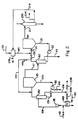
- a beneficiated clay slurry 1 to be concentrated to a higher solids content such as but not limited to an already partially dried beneficiated clay slurry typically having a solids content in the range of about 50% to about 60% by weight which is to be further dewatered to concentrate the solids therein to a level suitable for shipment, typically at least 65% solids by weight, is passed through a single non-contact type evaporative heat exchanger 25 in indirect contact with a heating liquid 6 wherein a portion of the water contained in the aqueous clay slurry is evaporated.
- the clay slurry leaving the evaporative heat exchanger 25 passes to a separating vessel 35 wherein the vapor evaporated from the clay slurry in the evaporative heat exchanger 25 is separated from the clay slurry.
- the clay slurry 21 leaving the separating vessel 35 has a higher solids content than the clay slurry feed 1 entering the system due to the evaporation of water therefrom as the clay slurry passes in heat exchange relationship with the heating liquid 6. It is to be understood that the separating vessel 35 may be housed independently of the heat exchanger vessel 25 as shown in the drawing or, if desired, formed integrally with the heat exchanger in a single vessel.
- the separating vessel 35 is maintained under a vacuum, preferably at an absolute pressure of about 2 inches mercury at which absolute pressure evaporation will occur at a temperature of about 100°F (37.7°C). Accordingly, when the heated clay slurry 11 is discharged from the heat exchanger 25 into the separating vessel 35, water vapor is released from the heated clay slurry 11 thereby concentrating the solids in the clay slurry such that the clay slurry 21 leaving the separating vessel 35 has a higher solids content than the clay slurry 1 being supplied to the system.
- the low solids clay slurry 1 entering the system is mixed with the heated clay slurry 11 passing from the heat exchanger 25 to the separating vessel 35.
- the incoming low solids clay slurry 1 may be introduced into the system at other locations without departing from the spirit and scopy of the present invention.
- a clay slurry recirculation loop is provided for recirculating at least a portion 31 of the higher solids clay slurry 21 back through the heat exchanger 25 and the separator vessel 35 to permit further evaporation of water from the clay slurry.
- the recirculation loop provides a clay slurry flow passage from the outlet of the discharge of the separating vessel 35 to the clay feed inlet of the heat exchanger 25 and includes a slurry circulation pump 40 disposed in the recirculation loop therebetween for pumping the clay slurry through the circuit.
- Valves 33 and 43 are provided in the discharge line from the separating vessel 35 so that the flow of the higher solids clay slurry 21 discharged from the separating vessel 35 may be selectively proportioned between the heat exchanger feed flow 31 and product flow 41 streams.
- the flow of clay slurry 21 passing through the recirculation loop is mixed with incoming lower solids feed slurry 1 whereby the solids content of the resultant clay slurry mixture being passed through the heat exchanger 25 and separator vessel 35 is initially increased which in turn results in the clay slurry 21 having a still higher content.
- the heating liquid 6 is preferably circulated under forced circulation via pump means 15 through heat exchanger 25 in indirect heat exchange relationship with the clay slurry 31.
- the heat exchanger 25 comprise a plate and frame type heat exchanger wherein the clay slurry 31 and the heating liquid 6 are passed through alternate flow passages formed between spaced heat transfer plates within the heat exchanger frame.
- the cool heating liquid 8 may be recirculated after reheating by forced circulation pump means 15 by venting valve 28 and closing valve 38.
- the cool heating fluid 8 is reheated by transferring waste heat from elsewhere in the kaolin processing plant to reheat the heating fluid to the desired temperature.
- a particularly advantageous source of such waste heat would be the hot exhaust gas from a calciner or a spray dryer.
- the recirculation heating fluid may be through an indirect heat exchanger 45 in indirect heat exchange relationship with a heating fluid, such as hot exhaust gas 40a, to recover waste heat contained therein.
- the cool heating fluid 8 may be passed to waste or directed for use elsewhere in the kaolin processing plant by opening valve 33 and closing the recirculation line valve 23.
- valve 13 would be opened to supply a continuous flow of heating fluid 2 from a source elsewhere in the kaolin processing plant.
- the heating fluid 2 is preferably heated via recovered waste heat by passing the heating fluid 2 in indirect heat exchange relationship with a heating fluid, such as hot exhaust gas.
- the generated vapor 17 is passed from the separating vessel 35 through condenser 55 in heat exchange relationship with a cooling fluid 57 to condense the vapor 17 to produce a condensate 19 comprises condensed water vapor previously evaporated from the clay slurry.
- Any non-condensible gases 9, typically leakage air and some carbon dioxide, present in the condensate discharging from the condenser 55 are vented to vacuum.
- the condensed water vapor 19 may be utilized elsewhere in the clay processing or heated with waste heat, such as hereinbefore described with respect to the circulating heating fluid, and utilized to form at least a part of the heating fluid 6 to be passed in indirect heat exchange relationship with the clay slurry 1 passing through the heat exchanger 25.
- the condensate 19 may be used as a heating medium by passing the condensate 19 in heat exchange relationship with the clay slurry feed 1 thereby preheating the clay slurry 1 prior to passing it through heat exchanger 25 and thereby recovering as heat a portion of the energy expended in evaporating the water from the clay.
- the condenser 55 comprises a direct contact type condenser, such as a spray tower wherein the vapor 17 would be contacted by a spray of cooling liquid to cause the condensation of the vapor.
- a direct contact type condenser such as a spray tower wherein the vapor 17 would be contacted by a spray of cooling liquid to cause the condensation of the vapor.
- the condensate 19 would comprise not only the condensed vapor but also heated cooling liquid, whereby the heat of condensation released by the vapor 17 as it condenses is recovered directly in the condensate 19.
- Lower heating fluid temperature may be utilized if the effective heat transfer surface area of the heat exchanger 25 is increased.
- approximately 38.96 tons/hour (3.53 x 10⁴ kg/hour) of clay slurry having a solids content of 72% could be produced using a single indirect evaporative heat exchanger arrangement, such as shown in Figure 1, to carry out the process of the present invention by passing approximately 46.76 tons/hour (4.24 x 10⁴ kg/hour) of 60% solids clay slurry feed preheated to 100°F (37.7°C) through an indirect heat exchanger having an effective heat transfer surface area of about 14,254 square feet (1324 m2) in indirect heat exchange relationship with about 1,290 gallons (4883 litres) per minute of hot water to heat the clay slurry to a temperature of 110°F (43.3°C) and then venting the heated slurry to a separating vessel maintained under vacuum at an absolute pressure of 1.932 inches (49mm) of mercury.
- each evaporative heat exchanger comprises a heat exchanger section wherein the clay slurry is passed in indirect heat exchange relationship with a heating medium and a separator section wherein the heated clay slurry is received from the heat exchanger section and the water vapor is released therefrom.
- FIG. 2 An example of such a multiple evaporative heat exchanger arrangement is the series arrangement of two evaporative heat exchanger/separating vessel assemblies 60,65 and 80,85 illustrated in Figure 2.
- the beneficiated kaolin clay slurry to be concentrated to a higher solids content such as but not limited to an already partially dried beneficiated clay slurry typically having a solids content in the range of about 50% to about 60% by weight which is to be further dewatered to concentrate the solids therein to a level suitable for shipment, typically at least 65% solids by weight, is passed in series flow relationship through a first non-contact type evaporative heat exchanger in indirect contact with a first heating medium wherein a portion of the water contained in the aqueous clay slurry is evaporated.
- the aqueous clay slurry is then passed through a second non-contact type evaporative heat exchanger in indirect contact with a second heating medium wherein additional water contained in the aqueous clay slurry is evaporated to further concentrate the aqueous clay slurry to a higher solids content.
- a first heat exchanger/separating vessel assembly 60,65 and a second heat exchanger/separating vessel assembly 80,85 are arranged in series flow arrangement with respect to clay slurry flow.
- the aqueous kaolin clay slurry is first passed through the first exchanger/separating vessel assembly 60,65 wherein it is passed in indirect heat exchange relationship with a heating medium, which constitutes water vapor evaporated from the clay slurry as it passes thereafter through the second heat exchanger/ separating vessel assembly 80,85, wherein the aqueous clay slurry is passed in indirect heat exchange relationship with a hot heating fluid, preferably hot water having a temperature ranging from about 120°F (48.9°C) to about 200°F (93.3°C).
- a hot heating fluid preferably hot water having a temperature ranging from about 120°F (48.9°C) to about 200°F (93.3°C).
- Each of the evaporative heat exchanger/separating vessel assemblies 60,65 and 80,85 in the multiple evaporator arrangement comprise a basic single evaporator of the type shown in Figure 1 and previously described herein. That is, each of the evaporator assemblies 60,65 and 80,85 comprise, respectively, an indirect heat exchanger 60,80 and a separating vessel 65,85 maintained at a vacuum and interconnected its respective heat exchanger via a clay slurry flow recirculation loop.
- the clay slurry feed 101 to be concentrated is mixed with the clay slurry 111 leaving the first heat exchanger 60 and passing to the separating vessel 65 which is maintained under a vacuum, preferably at an absolute pressure of about 2 inches (50.8mm) mercury at which absolute pressure evaporation will occur at a temperature of about 100°F (37.7°C).
- a vacuum preferably at an absolute pressure of about 2 inches (50.8mm) mercury at which absolute pressure evaporation will occur at a temperature of about 100°F (37.7°C).
- the clay slurry 121 leaving the separating vessel 65 is preferably recirculated via slurry pump 62 back through the heat exchanger 60 to reheat the clay slurry.
- a first portion 111 of the heated clay slurry is recirculated back through the separating vessel 65 to further evaporate water therefrom, while a second portion 201 of the heated aqueous clay slurry leaving the first heat exchanger 60 is passed to the separating vessel 85 of the second evaporative heat exchanger/separating vessel assembly.
- Valves 133 and 143 are provided in the discharge line from the indirect heat exchanger 60 may be selectively proportioned between the separating vessel 65 and the separating vessel 85 to optimize the process of concentrating the clay slurry to obtain a higher solids content in the most energy efficient manner.
- the generated vapor 217 is passed from the separating vessel 65 through condenser 255 in heat exchange relationship with a cooling fluid to condense the vapor 217 to produce a condensate 219 comprising condensed water vapor previously evaporated from the clay slurry.
- Any non-condensible gases 209, typically leakage air and some carbon dioxide, present in the condensate discharging from the condenser 255 are vented to vacuum.
- the heated aqueous clay slurry 201 passing from the first heat exchanger 60 is mixed with the flow of heated clay slurry passing from the second heat exchanger 80 and the mixture thereof introduced into the vacuum chamber of the second separating vessel 85 wherein the water is evaporated from the heated clay slurry and separated as a heated vapor 117 thereby producing a discharge clay slurry 221 having a higher solids content than the clay slurry mixture supplied to the separating vessel 85.
- a clay slurry recirculation loop is provided for recirculating at least a portion 231 of the higher solids clay slurry 221 back through the heat exchanger 80 and the separator vessel 85 to permit further evaporation of water from the clay slurry.
- the recirculation loop provides a clay slurry flow passage from the outlet of the discharge of the separating vessel 85 to the clay feed inlet of the heat exchanger 80 and includes a slurry circulation pump 82 disposed in the recirculation loop therebetween for pumping the clay slurry through the circuit.
- Valves are provided in the discharge line from the separating vessel 85 so that the flow of the higher solids clay slurry 221 discharged from the separating vessel 85 may be selectively proportioned between the heat exchanger feed flow 231 and product flow 241 streams.
- a higher solids product may be attained under steady state conditions using a single heat exchanger arrangement than would be attainable under steady state conditions without recirculation.
- Operational steady state recirculation ratios in commercial practice would typically range from 10 to 30, with the recirculated ratio being the volume flow of recirculating slurry of the volume flow of feed slurry.
- the heating liquid 106 preferably comprises hot water having a temperature in the range of 160°F (71.1°C) to 200°F (93.3°C). Although such hot water 112 may be available under continuous flow conditions from another source in the plant, it is preferable to reheat the cooled heating liquid 108 discharged from the indirect heat exchanger 80 and recirculate the reheated liquid via a circulation pump 115 back through the heat exchanger 80 as the heating liquid in heat exchange relationship with the clay slurry. As noted previously in the discussion of the single evaporator arrangement, the cool heating fluid 108 may be reheated by transferring waste heat from elsewhere in the kaolin processing plant to reheat the heating fluid to the desired temperature.
- a particularly advantageous source of such waste heat would be the hot exhaust gas from a calciner or a spray dryer.
- the recirculating fluid may be passed through an indirect heat exchanger 145 in indirect heat exchange relationship with a stream of hot exhaust gas 40.
- the hot vapor 117 separated from the heated clay slurry in the second separating vessel 85 serves as the heating medium to drive the first heat exchanger 60.
- the hot vapor 117 is passed from the second separating vessel 85 through the first heat exchanger 60 in indirect heat exchange relationship with the aqueous clay slurry 121 to produce the heated clay slurry 111.
- the hot vapor 117 is preferably condensed in the heat exchange process thereby recovering the heat of vaporization in addition to sensible heat contained in the vapor 117.
- the condensate 119, and/or 219 may be used as a heating medium by passing the condensate in heat exchange relationship with the clay slurry feed 101 thereby preheating the clay slurry 101 prior to passing it through the first heat exchanger/separating vessel assembly and thereby recovering as heat a portion of the energy expended in evaporating the water from the clay.
- the condenser 255 comprises a direct contact type condenser, such as a spray tower wherein the vapor 217 would be contacted by a spray of cooling liquid to cause the condensation of the vapor.
- a direct contact type condenser such as a spray tower wherein the vapor 217 would be contacted by a spray of cooling liquid to cause the condensation of the vapor.
- the condensate 219 would comprise not only the condensed vapor but also heated cooling liquid, whereby the heat of condensation released by the vapor 217 as it condenses is recovered directly in the condensate 219.
- the heated clay slurry discharging from the first heat exchanger 60 would be passed to the second separating vessel 85 at a solids content of 65.4 and thence through the second heat exchanger 80 in indirect heat exchange relationship with 650 gallons (2460 litres) per minute of 180°F (82.2°C) water.
- the first separating vessel 65 is maintained under vacuum at an absolute pressure of about 1.932 inches (49mm) mercury to promote evaporation at a temperature of about 100°F (37.7°c)
- the second separating vessel 85 is maintained under vacuum at an absolute pressure of about 5.878 inches (149.3mm) mercury to promote evaporation at a temperature of about 140°F (60°C)
Landscapes
- Engineering & Computer Science (AREA)
- Mechanical Engineering (AREA)
- General Engineering & Computer Science (AREA)
- Health & Medical Sciences (AREA)
- Life Sciences & Earth Sciences (AREA)
- Molecular Biology (AREA)
- Vaporization, Distillation, Condensation, Sublimation, And Cold Traps (AREA)
- Paper (AREA)
Claims (15)
- Verfahren zum Konzentrieren von Feststoffen in einer wässerigen Kaolin-Tonaufschlämmung (1,201) durch Verdampfen von Wasser aus derselben, wobei die wässerige Kaolin-Tonaufschlämmung (1,201) in indirekter Wärmeaustauschbeziehung mit einem Heizmedium so geführt wird, daß die Tonaufschlämmung (1,201) erwärmt wird, ohne daß die Tonaufschlämmung (1,201) das Heizmedium berührt, wobei die so erwärmte wässerige Tonaufschlämmung (11,-) in eine erste unter Vakuum gehaltene Kammer (35,85) geführt wird, wodurch zumindest ein Tell des Wassers in der erwärmten wässerigen Tonaufschlämmung aus derselben verdampfen wird, um Wasserdampf (17,117) zu bilden, wodurch die Feststoffe in der wässerigen Tonaufschlämmung (1,201) konzentriert werden, wobei eine wässerige Tonaufschlämmung mit einem höheren Feststoffgehalt (21,221) hergestellt wird, dadurch gekennzeichnet, daß das Heizmedium (6,106) eine Flüssigkeit ist; und die in der ersten Kammer hergestellte wässerige Tonaufschlämmung mit höherem Feststoffgehalt (21,221) in einen ersten Anteil (31,231) und einen zweiten Anteil (41,241) selektiv geteilt wird, der erste Anteil (31,231) mit der einlaufenden wässerigen Kaolin-Tonaufschlämmung (1,201) gemischt und in indirekter Wärmeaustauschbeziehung mit dem Heizmedium (6,106) rückgeführt wird und der zweite Anteil (41,241) als Produkt ausgestoßen wird.
- Verfahren zum Konzentrieren von Feststoffen in einer wässerigen Tonaufschlämmung (1,201) durch Verdampfen von Wasser aus derselben, wie im Anspruch 1 beansprucht, wobei die in indirekter Wärmeaustauschbeziehung mit der Heizflüssigkeit geführte wässerige Tonaufschlämmung (1,201) die Kaolin-Tonaufschlämmung auf eine Temperatur von etwa 110°F (43,3°C) erwärmt.
- Verfahren zum Konzentrieren von Feststoffen in einer wässerigen Tonaufschlämmung (1,201) durch Verdampfen von Wasser aus derselben, wie im Anspruch 1 oder 2 beansprucht, wobei die erste Kammer unter Vakuum bei einem absolutem Druck von etwa 2 Zoll (50,8 mm) Quecksilber gehalten wird.
- Verfahren zum Konzentrieren von Feststoffen in einer wässerigen Tonaufschlämmung (1,201) durch Verdampfen von Wasser aus derselben, wie im Anspruch 1, 2 oder 3 beansprucht, wobei das Heizmedium (6,106) heißes Wasser mit einer Temperatur im Bereich von 120°F bis 200°F (48,9°C bis 93,3°C) umfaßt.
- Verfahren zum Konzentrieren von Feststoffen in einer wässerigen Tonaufschlämmung (1,201) durch Verdampfen von Wasser aus derselben, wie in einem der vorhergehenden Ansprüche beansprucht, welches weiters das Erwärmen des das Heizmedium (6, 106) umfassenden Wassers auf eine Temperatur im Bereich von 120°F bis 200°F (48,9°C bis 93,3°C) durch Führen des Wassers in Wärmeaustauschbeziehung mit einem heißen Gas zum Gewinnen von Abwärme aus dem heißen Gas umfaßt.
- Verfahren zum Konzentrieren von Feststoffen in einer wässerigen Tonaufschlämmung (1,201) durch Verdampfen von Wasser aus derselben, wie in einem der vorhergehenden Ansprüche beansprucht, welches weiters das selektive Proportionieren der in der ersten Kammer (35,85) hergestellten wässerigen Tonaufschlämmung mit höherem Feststoffgehalt (21,221) in den ersten Anteil (31,231) und den zweiten Anteil (41,241), so daß das Verhältnis des Flußvolumens des ersten Anteils (31,231) zum Flußvolumen der zu konzentrierenden hereinkommenden wässerigen Tonaufschlämmung (1,201) im Bereich von 10 zu 30 liegt, umfaßt.
- Verfahren zum Konzentrieren von Peststoffen in einer wässerigen Tonaufschlämmung (201) durch Verdampfen von Wasser aus derselben, wie in einem der vorhergehenden Ansprüche beansprucht, worin der aus der ersten Kammer (85) verdampfte Wasserdampf (117) verwendet wird, die Tonaufschlämmung (201) vor ihrer Erwärmung durch das Heizmedium (106) durch Führen der Tonaufschlämmung mit niedrigerem Feststoffgehalt (101) in indirektem Wärmeaustausch mit dem heißen Wasserdampf (117) zu erwärmen und danach durch Führen der dadurch erwärmten Aufschlämmung mit niedrigerem Feststoffgehalt (111) in eine unter Vakuum gehaltene zweite Kammer (65), wobei ein Teil des Wassers in der erwärmten wässerigen Tonaufschlämmung mit niedrigerem Feststoffgehalt (111) aus derselben verdampfen wird, um Wasserdampf (217) zu bilden, wodurch die erwärmte wässerige Tonaufschlämmung (111) teilweise entwässert wird, bevor dieselbe in indirektem Wärmeaustausch mit dem heißen flüssigen Heizmedium (106) geführt wird.
- Verfahren zum Konzentrieren von Feststoffen in einer wässerigen Tonaufschlämmung (201) durch Verdampfen von Wasser aus derselben, wie im Anspruch 7 beansprucht, wobei das heiße flüssige Heizmedium (106) Wasser mit einer Temperatur im Bereich von 160°F bis 200°F (71,1°C bis 93,3°C) umfaßt.
- Verfahren zum Konzentrieren von Feststoffen in einer wässerigen Tonaufschlämmung (201) durch Verdampfen von Wasser aus derselben, wie im Anspruch 7 oder 8 beansprucht, wobei das Wasserdampf-Heizmedium (117) eine Temperatur im Bereich von 120°F bis 160°F (48,9°C bis 71,1°C) aufweist.
- Verfahren zum konzentrieren von Feststoffen in einer wässerigen Tonaufschlämmung (201) durch Verdampfen von Wasser aus derselben, wie im Anspruch 7, 8 oder 9 beansprucht, wobei die erste Vakuumkammer (85) bei einem absoluten Druck von etwa 6 Zoll (152,4 mm) Quecksilber gehalten wird.
- Verfahren zum Konzentrieren von Feststoffen in einer wässerigen Tonaufschlämmung (201) durch Verdampfen von Wasser aus derselben, wie in einem der Ansprüche 7 bis 10 beansprucht, wobei die zweite Vakuumkammer (65) bei einem absoluten Druck von etwa zwei Zoll (50,8 mm) Quecksilber gehalten wird.
- Verfahren zum Konzentrieren von Feststoffen in einer wässerigen Tonaufschlämmung (201) durch Verdampfen von Wasser aus derselben, wie in einem der Ansprüche 7 bis 11 beansprucht, wobei das das flüssige Heizmedium (106) umfassende Wasser auf eine Temperatur im Bereich von 160°F bis 200°F (71,1°C bis 93,3°C) durch Führen des Wassers in Wärmeaustauschbeziehung mit einem heißen Gas (40), um Abwärme aus dem heißen Gas (40) zu gewinnen, erwärmt wird.
- Vorrichtung zum Konzentrieren von Feststoffen in einer wässerigen Aufschlämmung (1,201) durch Verdampfen von Wasser aus derselben, worin die wässerige Aufschlämmung (1,201) in indirekter Wärmeaustauschbeziehung mit einem Heizmedium (6,106) geführt wird, wodurch Wasser aus der wässerigen Aufschlämmung (1,201) mittels des Heizmediums (6,106) verdampft wird, welche Vorrichtung umfaßt:(a) ein erstes Wärmeaustauschmittel (25,80) zum Führen der wässerigen Aufschlämmung (1,201) in indirekter Wärmeaustauschbeziehung mit einem heißen Heizmedium (6,106), wodurch die wässerige Aufschlämmung (1,201) erwärmt und die Heizflüssigkeit (6,106) abgekühlt wird; und(b) ein erstes Kammermittel (35,85), welches mit dem ersten Wärmeaustauschmittel (25,80) wirkungsmäßig verbunden ist, um zumindest einen Anteil (11,-) der durch das erste Wärmeaustauschmittel (25,80) geführten, erwärmten wässerigen Aufschlämmung (1,201) aufzunehmen, wobei dieses erste Kammermittel (35,80) unter ausreichendem Vakuum gehalten wird, um zu bewirken, daß das Wasser aus der erwärmten wässerigen Aufschlämmung in das erste Kammermittel (35,80) als Dampf verdampft;dadurch gekennzeichnet, daß das erste Wärmeaustauschmittel für die Verwendung mit einem flüssigen heißen Heizmedium ausgelegt ist, und daß die Vorrichtung weiters umfaßt:(c) ein erstes Rückführmittel (40,82), welches das erste Heizaustauschmittel (25,80) und das erste Kammermittel (35,85) in Aufschlämmungsflußverbindung zum Zirkulieren von zumindest einem Anteil der wässerigen Aufschlämmung (21,221) im Kreislauf durch das erste Wärmeaustauschmittel (25,80) und durch das erste Kammermittel (35,80) wirkungsmäßig miteinander verbindet; und(d) erste Ventilmittel (33,43), welche mit dem ersten Rückführmittel (40,82) zum selektiven Proportionieren der wässerigen Tonaufschlämmung (21,221) in einen ersten Anteil (31,231), welcher im Kreislauffluß durch das erste Wärmeaustauschmittel (25,80) und durch das erste Kammermittel (35,85) geführt wird, und in einen zweiten Anteil (41,241), welcher aus der Vorrichtung als ein wässeriges Aufschlämmungsprodukt mit höherem Feststoffgehalt geführt wird, wirkungsmäßig verbunden sind.
- Vorrichtung zum Konzentrieren von Feststoffen in einer wässerigen Aufschlämmung, wie im Anspruch 13 beansprucht, welche weiters umfaßt:(e) ein zweites Wärmeaustauschmittel (60) zum Führen der wässerigen Aufschlämmung mit niedrigerem Feststoffgehalt (101) in indirekter Wärmeaustauschbeziehung mit einem heißen Heizdampf (117), der aus dem ersten Kammermittel (85) aufgenommen wird, wodurch die wässerige Aufschlämmung (101) erwärmt und der Heizdampf (117) abgekühlt wird;(f) ein zweites Kammermittel (65), welches ait dem zweiten Wärmeaustauschmittel (60) wirkungsmäßig verbunden ist, zum Aufnehmen von zumindest einem Anteil der erwärmten wässerigen Aufschlämmung (111), welche durch das zweite Wärmeaustauschmittel (60) geführt wurde, wobei das zweite Kammermittel (65) unter ausreichendem Vakuum gehalten wird, um das Verdampfen von Wasser aus der erwärmten wässerigen Aufschlämmung (111) in das zweite Kammermittel als Dampf zu bewirken;(g) ein zweites Rückführmittel (62), welches das zweite Wärmeaustauschmittel (60) und das zweite Kammermittel (65) in Aufschlämmungsflußverbindung zum Zirkulieren von zumindest einem Anteil der wässerigen Aufschlämmung (121) in einem zweiten Kreislauffluß durch das zweite Wärmeaustauschmittel (60) und durch das zweite Kammermittel (65) wirkungsmäßig miteinander verbindet;(h) zweite Ventilmittel (133,143), welche mit dem zweiten Rückführmittel zum selektiven Proportionieren der wässerigen Tonaufschlämmung in einen ersten Anteil (111), welcher durch das zweite Wärmeaustauschmittel und durch das zweite Kammermittel im Kreislauffluß geführt wird, und einen zweiten Anteil (201), der zum ersten Wärmeaustauschmittel (80) geleitet wird, um in diesem in indirektem Wärmeaustausch mit der Heizflüssigkeit (106) geführt zu werden, wobei die wässerige Tonaufschlämmung weiter erwärmt wird, wirkungsmäßig verbunden sind.
- Vorrichtung, wie im Anspruch 13 oder 14 beansprucht, welche weiters ein drittes Wärmeaustauschmittel (45,145) zum Erwärmen der Heizflüssigkeit (6,106), welche dem ersten Wärmeaustauschmittel (25,80) durch Führen der Heizflüssigkeit (6,106) in Wärmeaustauschbeziehung mit einem heißen Gas (40), um Abwärme aus dem heißen Gas (40) zu gewinnen, zugeführt wird, umfaßt.
Applications Claiming Priority (2)
| Application Number | Priority Date | Filing Date | Title |
|---|---|---|---|
| US290135 | 1988-12-27 | ||
| US07/290,135 US5036599A (en) | 1988-12-27 | 1988-12-27 | Method of concentrating slurried kaolin |
Publications (2)
| Publication Number | Publication Date |
|---|---|
| EP0409942A1 EP0409942A1 (de) | 1991-01-30 |
| EP0409942B1 true EP0409942B1 (de) | 1993-01-13 |
Family
ID=23114688
Family Applications (1)
| Application Number | Title | Priority Date | Filing Date |
|---|---|---|---|
| EP90902103A Expired - Lifetime EP0409942B1 (de) | 1988-12-27 | 1989-11-30 | Verfahren und Vorrichtung zum Konzentrieren von breiartigem Kaolin |
Country Status (6)
| Country | Link |
|---|---|
| US (1) | US5036599A (de) |
| EP (1) | EP0409942B1 (de) |
| KR (2) | KR930010721B1 (de) |
| AU (1) | AU634753B2 (de) |
| BR (1) | BR8907285A (de) |
| WO (1) | WO1990007686A1 (de) |
Families Citing this family (15)
| Publication number | Priority date | Publication date | Assignee | Title |
|---|---|---|---|---|
| NZ246130A (en) * | 1991-12-31 | 1995-07-26 | Comalco Alu | System for concentrating clay slurry having evaporative effects in series with each effect having indirect heat exchanger with suppression of boiling of water in slurry |
| GB2275876B (en) * | 1993-03-12 | 1996-07-17 | Ecc Int Ltd | Grinding alkaline earth metal pigments |
| AU712384B2 (en) * | 1996-08-14 | 1999-11-04 | Imerys Minerals Limited | Compositions for coating sheet materials |
| CN1049364C (zh) * | 1997-11-21 | 2000-02-16 | 四川省环境保护科学研究院 | 无蒸汽产物的蒸发浓缩方法 |
| US6454907B1 (en) | 1999-04-19 | 2002-09-24 | Minerals Technologies, Inc. | Method and apparatus for concentrating slurried solids |
| NZ516247A (en) * | 1999-05-31 | 2004-02-27 | Anhydro As | Concentration of liquid products |
| DE19947847A1 (de) * | 1999-10-04 | 2001-04-19 | Fischermanns Gmbh & Co Duisbur | Produkt, gewonnen aus Rinderfetten und/oder Schweinefetten und Verfahren zu seiner Herstellung |
| US6402824B1 (en) | 2000-05-26 | 2002-06-11 | J. M. Huber Corporation | Processes for preparing precipitated calcium carbonate compositions and the products thereof |
| US7806978B2 (en) * | 2002-12-16 | 2010-10-05 | Imerys Pigments, Inc. | Fine platy kaolin composition |
| US20070054797A1 (en) * | 2003-08-09 | 2007-03-08 | Thomas Ronald J | Siliceous clay slurry |
| US7105466B2 (en) * | 2003-08-09 | 2006-09-12 | H.C. Spinks Clay Company, Inc. | Siliceous clay slurry |
| US7091148B2 (en) * | 2003-08-09 | 2006-08-15 | H.C. Spinks Clay Company, Inc. | Silicious clay slurry |
| US20110000777A1 (en) * | 2009-07-03 | 2011-01-06 | Zhou yun yan | Vapor compression distillation system |
| US11243029B2 (en) * | 2019-04-26 | 2022-02-08 | Purdue Research Foundation | Process monitoring and control for lyophilization using a wireless sensor network |
| CN111821714B (zh) * | 2020-07-27 | 2021-07-20 | 华峰集团上海工程有限公司 | 一种聚酰胺用精盐连续浓缩系统 |
Family Cites Families (9)
| Publication number | Priority date | Publication date | Assignee | Title |
|---|---|---|---|---|
| BE506512A (de) * | ||||
| US3486740A (en) * | 1967-03-02 | 1969-12-30 | Packaged Power Terminals Inc | Apparatus for treating flowable materials |
| DE2360235A1 (de) * | 1973-12-04 | 1975-10-23 | Hoechst Ag | Verfahren zur trocknung von abwasserschlamm |
| DE2648219C3 (de) * | 1976-10-25 | 1979-04-05 | Wiegand Karlsruhe Gmbh, 7505 Ettlingen | Verfahren zum Erhitzen eines strömenden, von einem einzudampfenden und anschließend zu trocknenden Produkt verschiedenen Mediums, das z.B. als Heiz-, Transport- oder Behandlungsmittel für dieses Produkt dient |
| DE3030662A1 (de) * | 1980-08-13 | 1982-03-18 | Bayer Ag, 5090 Leverkusen | Verfahren zur trocknung von pumpfaehigen suspensionen |
| US4687546B1 (en) * | 1985-07-19 | 1996-06-04 | Anglo American Clays Corp | Method of concentrating slurried kaolin |
| US4642904A (en) * | 1985-08-01 | 1987-02-17 | Georgia Krolin Company, Inc. | Energy conserving process for drying a clay slurry |
| DE3629954A1 (de) * | 1986-09-03 | 1988-03-10 | Prehm Yorck Uwe Dipl Ing | Verfahren und vorrichtung zur entwaesserung von nassgut, insbesondere schlick |
| WO1989007743A1 (fr) * | 1988-02-20 | 1989-08-24 | Prehm Yorck Uwe | Procede et dispositif pour deshydrater des matieres humides, notamment des produits en vrac aqueux coulants et/ou versables |
-
1988
- 1988-12-27 US US07/290,135 patent/US5036599A/en not_active Expired - Lifetime
-
1989
- 1989-11-30 BR BR898907285A patent/BR8907285A/pt not_active IP Right Cessation
- 1989-11-30 WO PCT/US1989/005347 patent/WO1990007686A1/en not_active Ceased
- 1989-11-30 EP EP90902103A patent/EP0409942B1/de not_active Expired - Lifetime
- 1989-11-30 AU AU50277/90A patent/AU634753B2/en not_active Ceased
- 1989-11-30 KR KR1019900701881A patent/KR930010721B1/ko not_active Expired - Fee Related
- 1989-11-30 KR KR1019900701881A patent/KR910700438A/ko active Granted
Also Published As
| Publication number | Publication date |
|---|---|
| AU5027790A (en) | 1990-08-01 |
| US5036599A (en) | 1991-08-06 |
| KR930010721B1 (ko) | 1993-11-08 |
| KR910700438A (ko) | 1991-03-15 |
| BR8907285A (pt) | 1991-03-12 |
| WO1990007686A1 (en) | 1990-07-12 |
| AU634753B2 (en) | 1993-03-04 |
| EP0409942A1 (de) | 1991-01-30 |
Similar Documents
| Publication | Publication Date | Title |
|---|---|---|
| EP0232289B1 (de) | Verfahren zum konzentrieren von kaolinschlamm | |
| US5248387A (en) | Process for producing concentrated aqueous slurries and spray dried particulate products | |
| US5223088A (en) | Apparatus for producing concentrated aqueous slurries and spray dried particulate products | |
| US5036599A (en) | Method of concentrating slurried kaolin | |
| US4642904A (en) | Energy conserving process for drying a clay slurry | |
| DK2511637T3 (en) | Process for drying wet particulate matter, wherein the dried particle material is a white mineral having a brightness Ry of at least 65%, by drying in a direct superheated steam dryer | |
| US4760650A (en) | Method of drying particulate material | |
| EP0404864B1 (de) | Energiesparendes verfahren zum brennen von ton | |
| CN201155907Y (zh) | 干燥器 | |
| US4909899A (en) | Method of concentrating sludges | |
| CN107596706B (zh) | 一种蒸汽冷凝蒸发技术及装置 | |
| US5730836A (en) | Evaporative concentration of clay slurries | |
| US3425477A (en) | Method for heat recovery in evaporating and burning spent liquor | |
| US7895769B2 (en) | Method and a plant for thermally drying wet ground raw meal | |
| CN223268533U (zh) | 一种节能的污泥减量化的系统 | |
| WO2018109144A1 (en) | Plant and process for production of a dried product from a humid product | |
| DE68904427T2 (de) | Verfahren und vorrichtung zum konzentrieren von breiartigem kaolin. | |
| CN119591302A (zh) | 一种节能的污泥脱水干化的系统及方法 | |
| RU2158222C2 (ru) | Способ переработки боксита | |
| SU789398A1 (ru) | Установка дл термической обработки растворов | |
| Dickinson | Pre-concentration of feed stock | |
| CN218358396U (zh) | 一种湿法烟气脱硫装置 |
Legal Events
| Date | Code | Title | Description |
|---|---|---|---|
| PUAI | Public reference made under article 153(3) epc to a published international application that has entered the european phase |
Free format text: ORIGINAL CODE: 0009012 |
|
| 17P | Request for examination filed |
Effective date: 19900724 |
|
| AK | Designated contracting states |
Kind code of ref document: A1 Designated state(s): DE FR GB |
|
| 17Q | First examination report despatched |
Effective date: 19910212 |
|
| RAP1 | Party data changed (applicant data changed or rights of an application transferred) |
Owner name: GEORGIA KAOLIN COMPANY, INC. |
|
| GRAA | (expected) grant |
Free format text: ORIGINAL CODE: 0009210 |
|
| AK | Designated contracting states |
Kind code of ref document: B1 Designated state(s): DE FR GB |
|
| REF | Corresponds to: |
Ref document number: 68904427 Country of ref document: DE Date of ref document: 19930225 |
|
| ET | Fr: translation filed | ||
| PLBE | No opposition filed within time limit |
Free format text: ORIGINAL CODE: 0009261 |
|
| STAA | Information on the status of an ep patent application or granted ep patent |
Free format text: STATUS: NO OPPOSITION FILED WITHIN TIME LIMIT |
|
| 26N | No opposition filed | ||
| PGFP | Annual fee paid to national office [announced via postgrant information from national office to epo] |
Ref country code: FR Payment date: 19991102 Year of fee payment: 11 |
|
| PG25 | Lapsed in a contracting state [announced via postgrant information from national office to epo] |
Ref country code: FR Free format text: LAPSE BECAUSE OF NON-PAYMENT OF DUE FEES Effective date: 20010731 |
|
| REG | Reference to a national code |
Ref country code: FR Ref legal event code: ST |
|
| REG | Reference to a national code |
Ref country code: GB Ref legal event code: IF02 |
|
| REG | Reference to a national code |
Ref country code: GB Ref legal event code: 732E |
|
| PGFP | Annual fee paid to national office [announced via postgrant information from national office to epo] |
Ref country code: DE Payment date: 20081119 Year of fee payment: 20 |
|
| PGFP | Annual fee paid to national office [announced via postgrant information from national office to epo] |
Ref country code: GB Payment date: 20081022 Year of fee payment: 20 |
|
| REG | Reference to a national code |
Ref country code: GB Ref legal event code: PE20 Expiry date: 20091129 |
|
| PG25 | Lapsed in a contracting state [announced via postgrant information from national office to epo] |
Ref country code: GB Free format text: LAPSE BECAUSE OF EXPIRATION OF PROTECTION Effective date: 20091129 |