EP0409210B1 - Verfahren und Vorrichtung zum Unterscheiden zwischen genauer und ungenauer Blutdruckmessungen in Gegenwart eines Störsignales - Google Patents
Verfahren und Vorrichtung zum Unterscheiden zwischen genauer und ungenauer Blutdruckmessungen in Gegenwart eines Störsignales Download PDFInfo
- Publication number
- EP0409210B1 EP0409210B1 EP90113787A EP90113787A EP0409210B1 EP 0409210 B1 EP0409210 B1 EP 0409210B1 EP 90113787 A EP90113787 A EP 90113787A EP 90113787 A EP90113787 A EP 90113787A EP 0409210 B1 EP0409210 B1 EP 0409210B1
- Authority
- EP
- European Patent Office
- Prior art keywords
- pressure
- blood pressure
- pressures
- cuff
- mean arterial
- Prior art date
- Legal status (The legal status is an assumption and is not a legal conclusion. Google has not performed a legal analysis and makes no representation as to the accuracy of the status listed.)
- Expired - Lifetime
Links
Images


Classifications
-
- A—HUMAN NECESSITIES
- A61—MEDICAL OR VETERINARY SCIENCE; HYGIENE
- A61B—DIAGNOSIS; SURGERY; IDENTIFICATION
- A61B5/00—Measuring for diagnostic purposes; Identification of persons
- A61B5/02—Detecting, measuring or recording for evaluating the cardiovascular system, e.g. pulse, heart rate, blood pressure or blood flow
- A61B5/021—Measuring pressure in heart or blood vessels
- A61B5/022—Measuring pressure in heart or blood vessels by applying pressure to close blood vessels, e.g. against the skin; Ophthalmodynamometers
- A61B5/02225—Measuring pressure in heart or blood vessels by applying pressure to close blood vessels, e.g. against the skin; Ophthalmodynamometers using the oscillometric method
-
- A—HUMAN NECESSITIES
- A61—MEDICAL OR VETERINARY SCIENCE; HYGIENE
- A61B—DIAGNOSIS; SURGERY; IDENTIFICATION
- A61B5/00—Measuring for diagnostic purposes; Identification of persons
- A61B5/02—Detecting, measuring or recording for evaluating the cardiovascular system, e.g. pulse, heart rate, blood pressure or blood flow
- A61B5/021—Measuring pressure in heart or blood vessels
- A61B5/022—Measuring pressure in heart or blood vessels by applying pressure to close blood vessels, e.g. against the skin; Ophthalmodynamometers
Definitions
- This invention relates to a blood pressure monitor in accordance with the generic clause of claim 1 for screening out blood pressure measurements that are inaccurate because of artifact while allowing blood pressure measurements to be used if such measurements are accurate despite the presence of artifact.
- Automatic blood pressure monitors are commonly used to periodically measure the blood pressure of a patient.
- a pressure cuff is attached to a patient's arm over the brachial artery.
- the cuff is first pressurized with an applied pressure that is high enough to substantially occlude the brachial artery.
- the cuff pressure is then gradually reduced, either continuously or in increments. As the pressure is reduced to systolic pressure, the flow of blood through the brachial artery beneath the cuff increases substantially.
- the systolic, diastolic, and mean arterial blood pressures can then be determined from the values in the table using empirical definitions of these parameters as a function of the amplitudes of these oscillometric pulses.
- blood pressure measurements are often adversely affected by artifact, generally produced by patient movement. Motion-induced artifact can substantially alter the measured amplitude of oscillometric pulses thus introducing inaccuracies in the measurement of the patient's blood pressure.
- Some of these techniques may employ (a) the interval between oscillometric pulses or Korotkoff sounds or (b) the internal consistency of the oscillometric pulses, or (c) the relationship between oscillometric pulses, Korotkoff sounds and/or the QRS-complex of an EKG. Regardless of the method used to screen the blood pressure results, certain blood pressure measurements will fail the screening procedure. Measurements that fail the screening procedure are generally discarded and the doctor/patient is given a message indicating the reason for the failure of the measurement.
- the screening procedure may accept an INACCURATE measurement that should have been rejected.
- the second type of error results from false negatives, i.e. , the screening procedure may reject an accurate measurement that should have been accepted. As the screening procedure is made more stringent to minimize false positives, more false negatives will inherently occur.
- a blood pressure monitor as set out in the preamble of claim 1 is known from US-A-4 777 959.
- the primary object of the invention is to provide an apparatus for rejecting blood pressure measurements that are rendered inaccurate by artifact while allowing use of blood pressure measurements made in the presence of artifact as long as the artifact has not adversely affected the accuracy of such measurements.
- the inventive screening procedure determines whether or not those artifacts adversely affected the accuracy of the measurement. That determination is made by comparing the current results with previously recorded results and by assessing whether the relationship between measured systolic, diastolic and mean pressure varies from a physiologically realistic model.
- the internal consistency of the intervals separating oscillometric pulses at each cuff pressure is preferably used to indicate the presence of artifact.
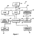
- Figure 1 is a block diagram of an automatic blood pressure monitor using the inventive system for distinguishing between accurate and INACCURATE measurements in the presence of artifact.
- Figures 2A and 2B are flow charts of software controlling the operation of a processor used in the system of Figure 1.
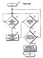
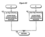
- Figure 3A, 3B and 3C are flow charts of an algorithm used in the program shown in Figure 2 to reject blood pressure measurements that have been adversely affected by artifact while accepting blood pressure measurements that have not been adversely affected by artifact.
- Figure 4 is a flow chart of an algorithm used in the program shown in Figure 3 to calculate a value of a blood pressure variable that is used to replace a value that has been adversely affected by artifact.
- FIG. 1 One embodiment of a system for screening against the deleterious effects of artifact in an automatic blood pressure measuring system is illustrated in Figure 1.
- the system 10 is composed of a number of hardware components, all of which are conventional.
- the system includes a conventional blood pressure cuff 12 in fluid communication with conduits 14 and 16, a conventional pump 18 a conventional valve 20, and a conventional pressure transducer 22.
- the pump 18 and valve 20 are operated by a conventional microprocessor 30.
- the blood pressure cuff 12 is inflated to a pressure that is greater than systole as indicated by the pressure transducer 22.
- the valve 20 is then opened usually for a predetermined period, although it may be continuously open to allow a slight leakage of air from the blood pressure cuff 12.
- the valve 20 normally allows air to escape from the cuff 12 fairly rapidly in relatively small increments.
- the pressure in the cuff 12 is reduced, either gradually or incrementally, the pressure in the cuff 12 is measured by the pressure transducer 22.
- the pressure in the blood pressure cuff 12 consists of two components, namely, a relatively constant, or "DC”, component and a relatively variable, or "AC”, component.
- the relatively constant component is a function of the pressure in the blood pressure cuff 12.
- the relatively variable component is produced by the minute change in the pressure of the cuff 12 following each contraction of the heart.
- the relatively constant DC component of the pressure in the cuff can be used as an indication of cuff pressure
- the relatively variable AC component of the pressure in the cuff 12 can be used as an indication of an oscillometric pulse.
- Two signals are obtained from the pressure transducer.
- One set of circuitry 34 supplies a DC component to an analog-to-digital (A/D) converter 32
- Another set of circuitry 36 supplies an AC component to the A/D converter 32.
- the signal supplied through the DC circuitry 34 is thus an indication of the cuff pressure while the signal supplied through the AC circuitry 36 is an indication of the oscillometric pulse.
- the A/D converter 32 digitizes the DC and the AC signals and outputs digital bytes indicative of their values through a bus 38 to the microprocessor 30.
- the microprocessor 30 is of conventional variety and, as is typical with such devices, is connected to a random access memory 40 used for the storage of data, and to either random access memory or read-only memory 42 that contains the software for operating the microprocessor 30.
- Operator controls 44 such as a keyboard or buttons, are also connected to the microprocessor 30.
- the measuring system 10 illustrated in Figure 1 utilizes a pressure transducer 22 and separate circuitry for the AC and the DC pressure signals, it will be understood that other implementations are possible.
- a single circuit providing a signal corresponding to both the steady-state and the variable pressures in the cuff 12 can be supplied to the analog-to-digital converter 32.
- the microprocessor 30 After the signal is digitized by analog-to-digital converter 32 and applied to the microprocessor 30.
- algorithms executed by the microprocessor 30 can detect the steady-state component of the cuff pressure and the variable component variations in the cuff pressure.
- the microprocessor 30 is controlled by software that is stored as a series of program instructions in the memory 42.
- a flow chart from which object code can be easily and quickly written by one skilled in the art is illustrated in Figures 2A and 2B.
- the program starts at 60, either through an operator command, automatically at power-up or when call by another prograrm stored in the memory 42.
- the system is initialized at 62 to set up the software for subsequent processing such as, for example, establishing tables that will subsequently contain data, by setting flu and by setting variables to known values.
- the program checks at 64 to determine if enough data has been collected to provide a blood pressure measurement.
- the decision block 64 is first encountered prior to obtaining any blood pressure dab Thus, when the program initially encounters decision block 64, enough data for a blood pressure determination will not have been collected. As a result, the program will branch to 66 to calculate a target value for the pressure in the blood pressure cuff 12 ( Figure 1). The target pressure for the cuff 12 will, of course, be in excess of the cuff pressure before the measurement is started. Tile microprocessor 30 then energizes the pump 18 ( Figure 1) at 68 while measuring the DC signal as digitized by the analog-to-digital convertor 32. The microprocessor continues to energize the pump 18 at 68 until the cuff pressure is equal to the target pressure. On subsequent passes through steps 66 and 68, the target pressure calculated at 66 will be lower than the pressure in the cuff 12. The microprocessor 30 will thus energize the valve 20 at 68 to reduce the pressure in the cuff 12 to the target pressure.
- the program progresses from 68 in Figure 2A to 71 in Figure 2B.
- the microprocessor 30 is interrupt driven in a conventional manner so that it periodically performs a clock driven interrupt service routine.
- the program waits at 71 until the interrupt has been serviced.
- the program then processes the digitized AC signal output at 74 and establishes the proper criteria for a set of samples being considered an oscillometric pulse.
- the program checks at 75 to see if the criteria established at 74 have been met.
- the criteria for determining if a set of samples is characteristic of an oscillometric pulse are conventional and are thus not explained herein. If the samples are not characteristic of an oscillometric pulse, the program returns to 71 to await another interrupt.
- the program branches to 76 to see if enough data had been collected at the current cuff pressure i.e . does the oscillometric peak meet amplitude and timing constraints of the algorithm? If enough data have not been collected, the program returns to 71 to await another interrupt, and then processes another sample at 74 and 75 as explained above, before once agin checking for sufficient data at 76. If the program determines at 76 that all of the pertinent data needed at a given cuff pressure had been collected, the program stores the data at 77 in appropriate tables. The DC component of the cuff pressure is stored along with amplitude and timing data of the AC oscillometric pulses. The program then returns via 78 to 64 to determine whether or not enough oscillometric pulses have been collected to determine the patient's blood pressure. The program will continue to loop through 64 - 78 until data have been obtained sufficient to allow the calculation of the patient's blood pressure.
- the data stored in the table after sufficient data have been obtained may appear for example as: CUFF PRESSURE PULSE AMPLITUDE 150 0 140 50 130 92 120 100 110 97 100 75 90 50 80 25 70 10
- the interval between oscillometric pulses are also stored and these data are used to calculate the heart rate as well as screen for motion artifacts.
- the program determines at 64 that sufficient data have been collected to determine a blood pressure, the program will then branch from 64 to 80, where the microprocessor 30 will continuously deflate the cuff 12.
- the program then calls subroutines to calculate (a) systole, (b) diastole and (c) mean arterial pressure 86.
- the algorithm to calculate systole and diastole is described in U. S. Patent No. 4,785,820 entitled Method And Apparatus For Systolic Blood Pressure Measurements .
- the algorithm to calculate mean arterial pressure is described in U. S. Patent Application No. 4,905,704 entitled Method And Apparatus For Determining The Mean Arterial Pressure In Automatic Blood Pressure Measurements . Therefore, in the interests of brevity, a complete explanation of these algorithms will not be included herein.
- An oscillometric pulse is produced by the flow of blood beneath the blood pressure cuff subsequent to each contraction of the heart.
- the interval between oscillometric pulses is thus indicative of the heart rate.
- Data indicative of the interval of time between subsequent oscillometric pulses is stored at 77.
- the heart rate is determined from this data at 86 along with the calculation of systole, diastole, and mean arterial pressure.
- the average interval between oscillometric pulses is calculated for all pertinent data
- the single interval which is most deviant from the average is found. If that most deviant interval is within some limit, the calculated average is accepted: it is converted into beats per minute. However, if the most deviant interval is outside the specification, it is discarded; and the average interval is re-calculated without that discarded interval. The process is repeated until the most deviant interval is within specification.
- a decision of whether or not the blood pressure passed the first screening technique is made. If the measurement passes, the results are accepted, displayed to the user and stored for future recall at 89.
- a failure at 88 would cause the measurement to be discarded.
- An event code would be displayed for the user and stored for later recall.
- the present invention inserts a second screening process after the fail decision had been made at 88. This second screening process is implemented at steps 90 and 91.
- the stored data of previous blood pressure measurements are analyzed at 90 according to the second screening process, as described in greater detail below.
- a decision is made as to whether or not the blood pressure measurement passed this second screening process. If the measurement passed, the algorithm branches to 89, where the results are accepted, displayed to the user and stored for future recall. If the stored data fails the second screening process, the algorithm branches to 92, where an event code is displayed and stored. In either case, the program ends at 93. At 93, the program may turn the power of the unit off, or return to the program which initially called it.
- the second screening process begins at 94.
- the average value for systole collected over some time period is calculated.
- a time period of 140 minutes is used.
- blood pressures are usually taken every 20 minutes while the patient is awake and once an hour while sleeping. Therefore, there is an opportunity to average 7 readings during waking hours and 2 readings during the sleeping hours.
- the current systole is compared to the calculated average at 96. To meet specifications, the current value of systole must be within 12.5% of the calculated average systole.
- a flag is set at 96 if the current value of systole is within this predetermined ranges and it is cleared in the current value of systole is outside this predetermined range. The algorithm is repeated for diastole at 97 and 98 and for mean arterial pressure at 99 and 100.
- the status of each of the flags set or cleared at 96, 98, 100 is exammed at 101 to determine whether or not they are all set, i.e. , all three parameters (systole, diastole, and mean arterial pressure) are within 12.5% of the calculated averages of these parameters. If they are within this predetermined range, the program branches to 102.
- the parameter RATIO defined as: The RATIO is a measure of the location of the mean arterial pressure between the diastolic and systolic pressures. For example, a RATIO of 0.5 means that the mean arterial pressure is midway between the diastolic and systolic pressures.
- the ratio is judged within specification and the program branches to 103.
- a flag is then set at 103 to indicate that the blood pressure measurement passed the second screening process. If the RATIO is not between 0.15 and 0.45 at 102, the program branches to 104, where the flag is cleared before the subroutine returns 105 to the main program.
- the measurement failed the first screening process it will nevertheless he considered accurate if (a) the systolic, diastolic and mean arterial pressures are within a predetermined range of the average of these pressures over an extended period of time and (2) if the relationship between the systolic, diastolic and mean arterial pressures are physiologically realistic, i.e . the mean arterial pressure is larger than the diastolic pressure by 15% - 45% of the difference between the systolic and diastolic pressures.
- the program branches to 106.
- the status of each of the flags set or cleared at 96, 98, 100 is examined to determine whether or not two out of the three flags are set, i.e. , two out of three parameters are within 12.5% of the average calculated for that value.) If two values are outside of that predetermined range, then the program branches to 104 where an event code is displayed to the user and stored for later recall.
- the program branches to 107.
- an average of the RATIO calculated at 102 over an extended period of time is calculated.
- a RATIO for a measurement is used only if the measurement:
- the program then proceeds to 108 were a value is calculated to replace the value (i.e. , diastolic, systolic or mean arterial pressure) that was not within a predetermined range of the average of such value.
- This value is calculated at 108 as a function of the two values that were within the predetermined range using an algorithm described below.
- This calculated replacement and the values that were within the predetermined range are compared with the average values of previously stored readings for systole at 109, diastole at 110, and mean arterial pressure at 111. These comparisons 109, 110, and 111 verify that the calculated replacement value meets the specifications of the second screening technique.
- the flags indicating whether or not the three values are within the predetermined range are checked at 112. If the flag for all three values are found to be set (i.e. , the values are within the predetermined range), then the program branches to 103 were a flag is set to indicate that the measurement passed the second screening process. If all three of the flags are not found to be set at 112, the program branches to 104, where the flag is cleared, indicating that the measurement failed the second screening process.
- the status of the pass or fail flag is checked at 91. Then the program either branches to 89 to accept, display and store the results or it branches to 92 to reject the results and display and store an event code.
- a replacement value is calculated at 108 in the event that a measured blood pressure value (i.e. , diastolic, systolic or mean arterial pressure) was not within a predetermined range of the average of such value.
- This value is calculated at 108 as a function of the two values that were within the predetermined range.
- the algorithum used to perform this calculation is illustrated in Figure 4.
- the subroutine is entered at 113, and a decision is made at 114 as to whether a replacement value for systole needs to be calculated. If a systole replacement needs to be calculated, the program branches to 115.
- the replacement systole value is calculated by the following formula: In the above formula, AVG. RATIO is the average of ratios calculated as a function of previously stored measurements which were calculated in 107.
- the replacement systole value is essentially the sum of the current diastole value and the difference between the average systole and diastole values except that the difference between the average systole and diastole values are first multiplied by a correction factor.
- the correction factor is equal to the ratio of the difference between the current mean arterial and diastole values to the average mean arterial and diastole values.
- the correction factor is, in effect, a measure of how the current systole value can be expected to deviate from the average systole value based on how the difference between the current mean and diastole values differ from the average mean and diastole values.
- the measurement must have:
- the AVG. RATIO used to calculate a replacement systolic value is given by: After systole is calculated at 115, the program returns to the calling program through 116. If a replacement value of systole is calculated, there is no reason to check diastole and mean arterial since the subroutine illustrated in Figure 4 is called only if one value is outside the predetermined range..
- the program branches to 116 to determine whether the current diastole value was within the predetermined range. If the diastole value was not within range, the program branches to 117 where a replacement diastole value is calculated by the following formula:
- the replacement diastole value is essentially the current systole value less the difference between the average systole and diastole values except that the average systole and diastole values are first multiplied by a correction factor.
- the correction factor is equal to the ratio of the difference between the current systole and mean arterial values to the difference between the average systole and mean arterial values.
- the correction factor is, in effect, a measure of how the current diastole value can be expected to deviate from the average diastole value based on how the difference between the current systole and mean arterial values differ from the average systole and mean arterial values.
- the program After diastole has been calculated at 117, the program returns to the calling program through 116. If a replacement value of diastole is calculated, there is no reason to check the mean arterial value since the subroutine illustrated in Figure 4 is called only if a single value is outside the predetermined range.
- the program branches to 118 to determine whether the current mean arterial pressure value was within the predetermined range. If the mean arterial value was within range the program returns to the calling program 116 without modifying any of the values since an error in the calling program must exist because the subroutine illustrated in Figure 4 should not have been entered unless one and only one of the values were outside the predetermined range.
Landscapes
- Health & Medical Sciences (AREA)
- Life Sciences & Earth Sciences (AREA)
- Vascular Medicine (AREA)
- Cardiology (AREA)
- Biomedical Technology (AREA)
- Heart & Thoracic Surgery (AREA)
- Physiology (AREA)
- Biophysics (AREA)
- Pathology (AREA)
- Engineering & Computer Science (AREA)
- Ophthalmology & Optometry (AREA)
- Physics & Mathematics (AREA)
- Medical Informatics (AREA)
- Molecular Biology (AREA)
- Surgery (AREA)
- Animal Behavior & Ethology (AREA)
- General Health & Medical Sciences (AREA)
- Public Health (AREA)
- Veterinary Medicine (AREA)
- Measuring Pulse, Heart Rate, Blood Pressure Or Blood Flow (AREA)
Claims (13)
- Ein Blutdrucküberwachungsgerät (10) umfassend:
eine Blutdruckmanschette (12);
eine Luftpumpe (18), die pneumatisch mit der genannten Blutdruckmanschette (12) gekoppelt ist;
ein Ventil (20), das mit der genannten Blutdruckmanschette (12) pneumatisch gekoppelt ist;
einen Druckwandler (22), der mit der genannten Blutdruckmanschette (12) pneumatisch gekoppelt ist, wobei der genannte Druckwandler ein Signal, das den Luftdruck in der genannten Blutdruckmanschette anzeigt, und ein Signal erzeugt, das den oszillometrischen Impulsen in der genannten Blutdruckmanschette entspricht;
eine Prozessoreinrichtung (30), die mit dem genannten Druckwandler verbunden ist und das genannte Signal, das den Luftdruck in der genannten Blutdruckmanschette anzeigt, und das genannte Signal erhält, das den oszillometrischen Impulsen in der genannten Blutdruckmanschette entspricht,
wobei die genannte Prozessoreinrichtung die genannte Luftpumpe erregt, um die genannte Blutdruckmanschette aufzublasen, periodisch das genannte Ventil erregt, um schrittweise den Luftdruck in der genannten Blutdruckmanschette zu verringern, und den Manschettendruck, bei dem jede Messung durchgeführt wird, und die Amplitude der oszillometrischen Impulse bei solchem Manschettendruck aufzuzeichnen,
der diastolische, der mittlere arterielle und der systolische Druck aus einer Tabelle (40) von Manschettendrücken und oszillometrische Impulsamplituden berechnet werden,
dadurch gekennzeichnet,
daß die Prozessoreinrichtung (30)
den Durchschnitt des diastolischen, des mittleren arteriellen und des systolischen Drucks berechnet, der in der genannten Tabelle für eine Vielzahl von Messungen aufgezeichnet ist,
den diastolischen, den mittleren arteriellen und den systolischen Druck, der in der genannten Tabelle für eine gegenwärtige Messung aufgezeichnet worden ist, mit dem Durchschnitt des diastolischen, des mittleren arteriellen bzw. des systolischen Drucks vergleicht, und
dann bestimmt, ob ein Störimpuls die Genauigkeit von irgendeinem in der genannten Tabelle aufgezeichneten Druck für eine gegenwärtige Messung nachteilig beeinflußt hat, indem bestimmt wird, ob eine vorbestimmte Anzahl der genannten Drücke, die in der genannten Tabelle für eine gegenwärtige Messung aufgezeichnet worden sind, von ihren entsprechenden durchschnittlichen Drücken um einen vorbestimmten Wert abweicht; und
ferner die Beziehung zwischen dem systolischen, dem diastolischen und dem mittleren arteriellen Druck mit einem physiologisch realistischen Modell vergleicht und bestimmt, daß die genannte gegenwärtige Messung nachteilig durch einen Störimpuls beeinträchtigt worden ist, wenn die Beziehung zwischen dem systolischen, dem diastolischen oder dem mittleren arteriellen Druck von dem genannten physiologisch realistischen Modell um einen vorbestimmten Wert abweicht. - Blutdrucküberwachungsgerät des Anspruchs 1, in dem die genannte Verarbeitungseinrichtung (30) die Beziehung zwischen dem systolischen, dem diastolischen und dem mittleren arteriellen Druck mit einem physiologisch realistischen Modell vergleicht, indem das Verhältnis des Unterschiedes zwischen dem genannten mittleren arteriellen Druck und dem genannten diastolischen Druck mit der Differenz zwischen dem genannten systolischen Druck und dem genannten diastolischen Druck berechnet wird.
- Das Blutdrucküberwachungsgerät des Anspruchs 2, in dem die genannte Verarbeitungseinrichtung (30) bestimmt, ob die Beziehung zwischen dem systolischen, dem diastolischen und dem mittleren arteriellen Druck von dem genannten physiologisch realistischen Modell um einen vorbestimmten Wert abweicht, indem bestimmt wird, ob das genannte Verhältnis innerhalb eines vorbestimmten Bereiches ist.
- Das Blutdrucküberwachungsgerät des Anspruchs 3, in dem der genannte vorbestimmte Bereich zwischen 0,15 und 0,45 ist.
- Das Blutdrucküberwachungsgerät des Anspruchs 1, in dem die genannte Verarbeitungseinrichtung einen Ersatzdruck für jeden der genannten gegenwärtigen Drücke berechnet, von dem die genannte Verarbeitungseinrichtung (30) bestimmt, daß er von seinem entsprechenden Durchschnittsdruck um einen vorbestimmten Wert abgewichen ist.
- Das Blutdrucküberwachungsgerät des Anspruchs 5, in dem die genannte Verarbeitungseinrichtung (30) einen diastolischen Ersatzdruck gemäß der Formel berechnet:


- Das Blutdrucküberwachungsgerät des Anspruchs 5, in dem die genannte Verarbeitungseinrichtung (30) einen systolischen Ersatzdruck gemäß der Formel berechnet:


- Das Blutdrucküberwachungsgerät des Anspruchs 5, in dem die genannte Verarbeitungseinrichtung (30) einen mittleren, arteriellen Ersatzdruck gemäß der Formel berechnet:


- Das Blutdrucküberwachungsgerät des Anspruchs 5, in dem die genannte Verarbeitungseinrichtung (30) einen Ersatzdruck solange berechnet, wie zwei der Drücke, die in der genannten Tabelle für die genannte gegenwärtige Messung aufgezeichnet worden sind, von ihren entsprechenden Durchschnittsdrücken nicht um den genannten vorbestimmten Wert abgewichen sind.
- Ein Blutdrucküberwachungsgerät des Anspruchs 1, das ferner fähig ist, einen Ersatzdruck aus der genannten Tabelle von Daten zu berechnen, die den diastolischen, den systolischen und den mittleren arteriellen Druck enthält, die von einer Vielzahl von Blutdruckmessungen in dem Fall erhalten worden sind, daß die Genauigkeit von einem der genannten Drücke schädlich durch einen Störimpuls beeinflußt worden ist, und daß ferner umfaßt
eine Einrichtung zum Berechnen des genannten Ersatzdrucks auf der Grundlage der Drücke in der genannten Tabelle, die nicht schädlich durch einen Störimpuls beeinflußt worden sind, und von Drücken in der genannten Tabelle von vorhergehenden Blutdruckmessungen. - Ein Blutdrucküberwachungsgerät des Anspruchs 10, in dem in dem Fall, daß der diastolische Druck nachteilig von dem Störimpuls beeinflußt worden ist, das genannte System einen diastolischen Ersatzdruck gemäß der Formel berechnet:


- Ein Blutdrucküberwachungsgerät des Anspruchs 10, in dem in dem Fall, daß der systolische Druck nachteilig von dem Störimpuls beeinflußt worden ist, das genannte System einen systolischen Ersatzdruck gemäß der Formel berechnet:


- Ein Blutdrucküberwachungsgerät des Anspruchs 10, in dem in dem Fall, daß der mittlere, arterielle Druck nachteilig von dem Störimpuls beeinflußt worden ist, das genannte System einen mittleren, arteriellen Ersatzdruck gemäß der Formel berechnet:


Applications Claiming Priority (2)
| Application Number | Priority Date | Filing Date | Title |
|---|---|---|---|
| US07/383,207 US5014714A (en) | 1989-07-19 | 1989-07-19 | Method and apparatus for distinguishing between accurate and inaccurate blood pressure measurements in the presence of artifact |
| US383207 | 1989-07-19 |
Publications (2)
| Publication Number | Publication Date |
|---|---|
| EP0409210A1 EP0409210A1 (de) | 1991-01-23 |
| EP0409210B1 true EP0409210B1 (de) | 1995-10-25 |
Family
ID=23512179
Family Applications (1)
| Application Number | Title | Priority Date | Filing Date |
|---|---|---|---|
| EP90113787A Expired - Lifetime EP0409210B1 (de) | 1989-07-19 | 1990-07-18 | Verfahren und Vorrichtung zum Unterscheiden zwischen genauer und ungenauer Blutdruckmessungen in Gegenwart eines Störsignales |
Country Status (5)
| Country | Link |
|---|---|
| US (1) | US5014714A (de) |
| EP (1) | EP0409210B1 (de) |
| JP (1) | JPH03218728A (de) |
| CA (1) | CA2021363C (de) |
| DE (1) | DE69023178T2 (de) |
Families Citing this family (47)
| Publication number | Priority date | Publication date | Assignee | Title |
|---|---|---|---|---|
| US5263485A (en) * | 1989-09-18 | 1993-11-23 | The Research Foundation Of State University Of New York | Combination esophageal catheter for the measurement of atrial pressure |
| US5339818A (en) * | 1989-09-20 | 1994-08-23 | University Of Utah Research Foundation | Method for determining blood pressure utilizing a neural network |
| US5392781A (en) * | 1991-04-16 | 1995-02-28 | Cardiodyne, Incorporated | Blood pressure monitoring in noisy environments |
| US5396896A (en) * | 1991-05-15 | 1995-03-14 | Chrono Dynamics, Ltd. | Medical pumping apparatus |
| US5253648A (en) * | 1991-10-11 | 1993-10-19 | Spacelabs Medical, Inc. | Method and apparatus for excluding artifacts from automatic blood pressure measurements |
| EP0563425B1 (de) * | 1992-04-02 | 1995-05-17 | Hewlett-Packard GmbH | Verfahren zum Messen von Artefakten in einem Blutdruckmessystem |
| US5443440A (en) * | 1993-06-11 | 1995-08-22 | Ndm Acquisition Corp. | Medical pumping apparatus |
| US5769801A (en) * | 1993-06-11 | 1998-06-23 | Ndm Acquisition Corp. | Medical pumping apparatus |
| US5542428A (en) * | 1995-03-23 | 1996-08-06 | Spacelabs Medical, Inc. | Method and apparatus for removing artifact encountered during automatic blood pressure measurements |
| JPH08322811A (ja) * | 1995-05-30 | 1996-12-10 | Nippon Colin Co Ltd | 自動血圧測定装置 |
| US5840049A (en) * | 1995-09-07 | 1998-11-24 | Kinetic Concepts, Inc. | Medical pumping apparatus |
| US5772634A (en) * | 1995-10-06 | 1998-06-30 | Zimmer, Inc. | Device for limiting distention fluid pressure during hysteroscopy |
| US6387065B1 (en) | 1996-09-30 | 2002-05-14 | Kinetic Concepts, Inc. | Remote controllable medical pumping apparatus |
| US5752919A (en) * | 1996-12-17 | 1998-05-19 | Johnson & Johnson Medical, Inc. | Mitigation of respiratory artifact in blood pressure signal using line segment smoothing |
| US6258037B1 (en) | 1999-06-25 | 2001-07-10 | Cardiodyne Division Of Luxtec Corporation | Measuring blood pressure in noisy environments |
| US6447457B1 (en) * | 1999-11-16 | 2002-09-10 | Microlife Intellectual Property Gmbh | Non invasive blood pressure monitor and a method for the non-invasive measurement of the blood pressure |
| US6475153B1 (en) * | 2000-05-10 | 2002-11-05 | Motorola Inc. | Method for obtaining blood pressure data from optical sensor |
| US6423010B1 (en) | 2000-10-04 | 2002-07-23 | Critikon Company, L.L.C. | Oscillometric blood pressure monitor with improved performance in the presence of arrhythmias |
| EP1258223A1 (de) * | 2001-05-14 | 2002-11-20 | Microlife Intellectual Property GmbH | Nichtinvasive Blutdruckmessung |
| US7198604B2 (en) * | 2003-03-18 | 2007-04-03 | Ge Medical Systems Information Technologies | Method and system for determination of pulse rate |
| JP4646195B2 (ja) * | 2004-08-12 | 2011-03-09 | 株式会社志成データム | 電子血圧計、電子血圧計の脈波データ補正方法、プログラムおよび記録媒体 |
| WO2007049174A1 (en) * | 2005-10-24 | 2007-05-03 | Philips Intellectual Property & Standards Gmbh | System and method for determining the blood pressure of a patient |
| US9026370B2 (en) | 2007-12-18 | 2015-05-05 | Hospira, Inc. | User interface improvements for medical devices |
| US8317752B2 (en) * | 2007-12-18 | 2012-11-27 | Hospira, Inc. | Touch screen system and navigation and programming methods for an infusion pump |
| US9240002B2 (en) | 2011-08-19 | 2016-01-19 | Hospira, Inc. | Systems and methods for a graphical interface including a graphical representation of medical data |
| WO2013090709A1 (en) | 2011-12-16 | 2013-06-20 | Hospira, Inc. | System for monitoring and delivering medication to a patient and method of using the same to minimize the risks associated with automated therapy |
| US9995611B2 (en) | 2012-03-30 | 2018-06-12 | Icu Medical, Inc. | Air detection system and method for detecting air in a pump of an infusion system |
| ES3028431T3 (en) | 2012-07-31 | 2025-06-19 | Icu Medical Inc | Patient care system for critical medications |
| US9301700B2 (en) * | 2012-09-27 | 2016-04-05 | Welch Allyn, Inc. | Configurable vital signs system |
| US9615756B2 (en) * | 2012-10-31 | 2017-04-11 | Cnsystems Medizintechnik Ag | Device and method for the continuous non-invasive measurement of blood pressure |
| AU2014268355B2 (en) | 2013-05-24 | 2018-06-14 | Icu Medical, Inc. | Multi-sensor infusion system for detecting air or an occlusion in the infusion system |
| WO2014194089A1 (en) | 2013-05-29 | 2014-12-04 | Hospira, Inc. | Infusion system which utilizes one or more sensors and additional information to make an air determination regarding the infusion system |
| WO2014194065A1 (en) | 2013-05-29 | 2014-12-04 | Hospira, Inc. | Infusion system and method of use which prevents over-saturation of an analog-to-digital converter |
| US11071467B2 (en) | 2013-08-08 | 2021-07-27 | Welch Allyn, Inc. | Hybrid patient monitoring system |
| JP6636442B2 (ja) | 2014-02-28 | 2020-01-29 | アイシーユー・メディカル・インコーポレーテッド | 2波長の光学的な管路内空気検出を利用する輸液システムおよび方法 |
| US11344673B2 (en) | 2014-05-29 | 2022-05-31 | Icu Medical, Inc. | Infusion system and pump with configurable closed loop delivery rate catch-up |
| US11344668B2 (en) | 2014-12-19 | 2022-05-31 | Icu Medical, Inc. | Infusion system with concurrent TPN/insulin infusion |
| US10850024B2 (en) | 2015-03-02 | 2020-12-01 | Icu Medical, Inc. | Infusion system, device, and method having advanced infusion features |
| US11246985B2 (en) | 2016-05-13 | 2022-02-15 | Icu Medical, Inc. | Infusion pump system and method with common line auto flush |
| US11324888B2 (en) | 2016-06-10 | 2022-05-10 | Icu Medical, Inc. | Acoustic flow sensor for continuous medication flow measurements and feedback control of infusion |
| US10089055B1 (en) | 2017-12-27 | 2018-10-02 | Icu Medical, Inc. | Synchronized display of screen content on networked devices |
| EP3956903A4 (de) | 2019-04-17 | 2023-01-11 | ICU Medical, Inc. | System zur bordseitigen elektronischen codierung der inhalte und verabreichungsparameter von iv-behältern und deren sichere verwendung und entsorgung |
| US11278671B2 (en) | 2019-12-04 | 2022-03-22 | Icu Medical, Inc. | Infusion pump with safety sequence keypad |
| CA3189781A1 (en) | 2020-07-21 | 2022-01-27 | Icu Medical, Inc. | Fluid transfer devices and methods of use |
| US11135360B1 (en) | 2020-12-07 | 2021-10-05 | Icu Medical, Inc. | Concurrent infusion with common line auto flush |
| USD1091564S1 (en) | 2021-10-13 | 2025-09-02 | Icu Medical, Inc. | Display screen or portion thereof with graphical user interface for a medical device |
| WO2023108030A1 (en) | 2021-12-10 | 2023-06-15 | Icu Medical, Inc. | Medical fluid compounding systems with coordinated flow control |
Family Cites Families (6)
| Publication number | Priority date | Publication date | Assignee | Title |
|---|---|---|---|---|
| US4360029A (en) * | 1978-04-10 | 1982-11-23 | Johnson & Johnson | Automatic mean blood pressure reading device |
| US4543962A (en) * | 1984-07-09 | 1985-10-01 | Critikon, Inc. | Method of automated blood pressure detection |
| US4638810A (en) * | 1985-07-05 | 1987-01-27 | Critikon, Inc. | Automated diastolic blood pressure monitor with data enhancement |
| US4754761A (en) * | 1985-07-05 | 1988-07-05 | Critikon, Inc. | Automated mean arterial blood pressure monitor with data enhancement |
| JPH06110B2 (ja) * | 1985-08-27 | 1994-01-05 | オムロン株式会社 | 電子血圧計 |
| US4777959A (en) * | 1986-09-17 | 1988-10-18 | Spacelabs, Inc. | Artifact detection based on heart rate in a method and apparatus for indirect blood pressure measurement |
-
1989
- 1989-07-19 US US07/383,207 patent/US5014714A/en not_active Expired - Fee Related
-
1990
- 1990-07-17 CA CA002021363A patent/CA2021363C/en not_active Expired - Fee Related
- 1990-07-18 EP EP90113787A patent/EP0409210B1/de not_active Expired - Lifetime
- 1990-07-18 DE DE69023178T patent/DE69023178T2/de not_active Expired - Fee Related
- 1990-07-19 JP JP2191865A patent/JPH03218728A/ja active Pending
Also Published As
| Publication number | Publication date |
|---|---|
| DE69023178D1 (de) | 1995-11-30 |
| CA2021363A1 (en) | 1991-01-20 |
| EP0409210A1 (de) | 1991-01-23 |
| CA2021363C (en) | 1995-04-04 |
| US5014714A (en) | 1991-05-14 |
| DE69023178T2 (de) | 1996-04-04 |
| JPH03218728A (ja) | 1991-09-26 |
Similar Documents
| Publication | Publication Date | Title |
|---|---|---|
| EP0409210B1 (de) | Verfahren und Vorrichtung zum Unterscheiden zwischen genauer und ungenauer Blutdruckmessungen in Gegenwart eines Störsignales | |
| US5253648A (en) | Method and apparatus for excluding artifacts from automatic blood pressure measurements | |
| EP0207807B1 (de) | Gerät zur Überwachung des diastolischen Blutdruckes mit Daten-Aufbereitung | |
| US5337750A (en) | Automatic blood pressure monitor employing artifact rejection method and apparatus | |
| US4566463A (en) | Apparatus for automatically measuring blood pressure | |
| US4730621A (en) | Blood pressure measurement | |
| US6547742B2 (en) | Apparatus for measuring pulse-wave propagation velocity | |
| EP0353315B1 (de) | Verfahren und Vorrichtung zur automatischen Blutdruckmessung | |
| KR0165116B1 (ko) | 심장작위측정방법 및 그 장치 | |
| US7465273B2 (en) | Method for monitoring pre-eclamptic patients | |
| US6843772B2 (en) | Inferior-and-superior-limb blood-pressure-index measuring apparatus | |
| US5392781A (en) | Blood pressure monitoring in noisy environments | |
| US6440080B1 (en) | Automatic oscillometric apparatus and method for measuring blood pressure | |
| EP0261583B1 (de) | Verfahren und Gerät zur indirekten Blutdruckmessung | |
| US4735213A (en) | Device and method for determining systolic blood pressure | |
| EP0698370B1 (de) | Blutdruck-Überwachungsgerät | |
| US7300404B1 (en) | Method and system utilizing SpO2 plethysmograph signal to qualify NIBP pulses | |
| WO1988003003A1 (en) | Method and apparatus for measuring blood pressure | |
| EP0482242A1 (de) | Verfahren und Vorrichtung zur automatischen Blutdrucküberwachung | |
| US4677983A (en) | Method and apparatus for measuring circulatory function | |
| GB2381076A (en) | Non-invasive method for determining diastolic blood pressure | |
| US20020133083A1 (en) | Automatic blood-pressure measuring apparatus | |
| EP0379996B1 (de) | Verfahren und Vorrichtung zur Bestimmung des mittleren arteriellen Blutdruckes | |
| US5542428A (en) | Method and apparatus for removing artifact encountered during automatic blood pressure measurements | |
| EP1101440B1 (de) | Nichtinvasiver Blutdruckwächter |
Legal Events
| Date | Code | Title | Description |
|---|---|---|---|
| PUAI | Public reference made under article 153(3) epc to a published international application that has entered the european phase |
Free format text: ORIGINAL CODE: 0009012 |
|
| AK | Designated contracting states |
Kind code of ref document: A1 Designated state(s): CH DE FR GB IT LI |
|
| RIN1 | Information on inventor provided before grant (corrected) |
Inventor name: MILLAY, JACK M. Inventor name: WALLOCH, RICHARD A. |
|
| 17P | Request for examination filed |
Effective date: 19910718 |
|
| 17Q | First examination report despatched |
Effective date: 19930802 |
|
| RAP1 | Party data changed (applicant data changed or rights of an application transferred) |
Owner name: SPACELABS MEDICAL, INC. |
|
| GRAA | (expected) grant |
Free format text: ORIGINAL CODE: 0009210 |
|
| AK | Designated contracting states |
Kind code of ref document: B1 Designated state(s): CH DE FR GB IT LI |
|
| REF | Corresponds to: |
Ref document number: 69023178 Country of ref document: DE Date of ref document: 19951130 |
|
| ET | Fr: translation filed | ||
| ITF | It: translation for a ep patent filed | ||
| REG | Reference to a national code |
Ref country code: CH Ref legal event code: NV Representative=s name: BOVARD AG PATENTANWAELTE |
|
| PG25 | Lapsed in a contracting state [announced via postgrant information from national office to epo] |
Ref country code: GB Effective date: 19960718 |
|
| PG25 | Lapsed in a contracting state [announced via postgrant information from national office to epo] |
Ref country code: LI Effective date: 19960731 Ref country code: CH Effective date: 19960731 |
|
| PLBE | No opposition filed within time limit |
Free format text: ORIGINAL CODE: 0009261 |
|
| STAA | Information on the status of an ep patent application or granted ep patent |
Free format text: STATUS: NO OPPOSITION FILED WITHIN TIME LIMIT |
|
| 26N | No opposition filed | ||
| GBPC | Gb: european patent ceased through non-payment of renewal fee |
Effective date: 19960718 |
|
| REG | Reference to a national code |
Ref country code: CH Ref legal event code: PL |
|
| PG25 | Lapsed in a contracting state [announced via postgrant information from national office to epo] |
Ref country code: FR Effective date: 19970328 |
|
| PG25 | Lapsed in a contracting state [announced via postgrant information from national office to epo] |
Ref country code: DE Effective date: 19970402 |
|
| REG | Reference to a national code |
Ref country code: FR Ref legal event code: ST |
|
| PG25 | Lapsed in a contracting state [announced via postgrant information from national office to epo] |
Ref country code: IT Free format text: LAPSE BECAUSE OF NON-PAYMENT OF DUE FEES;WARNING: LAPSES OF ITALIAN PATENTS WITH EFFECTIVE DATE BEFORE 2007 MAY HAVE OCCURRED AT ANY TIME BEFORE 2007. THE CORRECT EFFECTIVE DATE MAY BE DIFFERENT FROM THE ONE RECORDED. Effective date: 20050718 |