US11071467B2 - Hybrid patient monitoring system - Google Patents
Hybrid patient monitoring system Download PDFInfo
- Publication number
- US11071467B2 US11071467B2 US14/454,225 US201414454225A US11071467B2 US 11071467 B2 US11071467 B2 US 11071467B2 US 201414454225 A US201414454225 A US 201414454225A US 11071467 B2 US11071467 B2 US 11071467B2
- Authority
- US
- United States
- Prior art keywords
- cuff
- manual
- control module
- pressure
- operating mode
- Prior art date
- Legal status (The legal status is an assumption and is not a legal conclusion. Google has not performed a legal analysis and makes no representation as to the accuracy of the status listed.)
- Active, expires
Links
Images


Classifications
-
- A—HUMAN NECESSITIES
- A61—MEDICAL OR VETERINARY SCIENCE; HYGIENE
- A61B—DIAGNOSIS; SURGERY; IDENTIFICATION
- A61B5/00—Measuring for diagnostic purposes; Identification of persons
- A61B5/02—Detecting, measuring or recording pulse, heart rate, blood pressure or blood flow; Combined pulse/heart-rate/blood pressure determination; Evaluating a cardiovascular condition not otherwise provided for, e.g. using combinations of techniques provided for in this group with electrocardiography or electroauscultation; Heart catheters for measuring blood pressure
- A61B5/021—Measuring pressure in heart or blood vessels
- A61B5/022—Measuring pressure in heart or blood vessels by applying pressure to close blood vessels, e.g. against the skin; Ophthalmodynamometers
- A61B5/0225—Measuring pressure in heart or blood vessels by applying pressure to close blood vessels, e.g. against the skin; Ophthalmodynamometers the pressure being controlled by electric signals, e.g. derived from Korotkoff sounds
-
- A—HUMAN NECESSITIES
- A61—MEDICAL OR VETERINARY SCIENCE; HYGIENE
- A61B—DIAGNOSIS; SURGERY; IDENTIFICATION
- A61B5/00—Measuring for diagnostic purposes; Identification of persons
- A61B5/02—Detecting, measuring or recording pulse, heart rate, blood pressure or blood flow; Combined pulse/heart-rate/blood pressure determination; Evaluating a cardiovascular condition not otherwise provided for, e.g. using combinations of techniques provided for in this group with electrocardiography or electroauscultation; Heart catheters for measuring blood pressure
- A61B5/02007—Evaluating blood vessel condition, e.g. elasticity, compliance
-
- A—HUMAN NECESSITIES
- A61—MEDICAL OR VETERINARY SCIENCE; HYGIENE
- A61B—DIAGNOSIS; SURGERY; IDENTIFICATION
- A61B5/00—Measuring for diagnostic purposes; Identification of persons
- A61B5/02—Detecting, measuring or recording pulse, heart rate, blood pressure or blood flow; Combined pulse/heart-rate/blood pressure determination; Evaluating a cardiovascular condition not otherwise provided for, e.g. using combinations of techniques provided for in this group with electrocardiography or electroauscultation; Heart catheters for measuring blood pressure
- A61B5/024—Detecting, measuring or recording pulse rate or heart rate
Definitions
- This application is directed to systems and methods for monitoring a patient, and in particular, to systems and methods for determining a hemodynamic parameter of a patient
- Traditional non-invasive blood pressure monitoring devices operate by inflating a blood pressure cuff to a pressure above a patient's systolic blood pressure. Because the systolic pressure is usually not known prior to inflation, the cuff must be inflated to such a pressure to ensure that the patient's arterial blood flow is completely occluded. Once above systole, pressure data collected during inflation and/or deflation of the cuff is used to determine, for example, systolic and diastolic pressures of the patient.
- a system for monitoring a patient includes a sensor configured to determine a first characteristic and a second characteristic of an at least partially occluded artery.
- the system also includes a control module in communication with the sensor and configured to determine a hemodynamic parameter of the patient based on the first and second characteristics.
- the control module is operable in an automatic operating mode and a manual operating mode.
- the automatic operating mode is characterized by the sensor determining, in response to one or more sensor control signals automatically generated by the control module, the first and second characteristics during at least one of automatic inflation and automatic deflation of a cuff associated with the control module.
- the manual operating mode is characterized by the sensor determining, in response to manual actuation of a trigger associated with the sensor, the first and second characteristics during at least one of inflation and deflation of the cuff.
- a method of determining a hemodynamic parameter of a patient includes selecting a first operating mode associated with a control module of a patient monitoring system, the system including a sensor in communication with the control module, and a trigger in communication with the sensor. The method also includes substantially occluding an artery of the patient while the system is under automatic control of the control module in the first operating mode, and determining, with the sensor and in response to one or more sensor control signals automatically generated by the control module, a first characteristic and a second characteristic associated with the artery while in the first operating mode. The method also includes selecting a second operating mode associated with the control module and substantially occluding the artery of the patient while in the second operating mode.
- the method further includes determining, with the sensor and in response to manual actuation of the trigger, a third characteristic and a fourth characteristic associated with the artery while in the second operating mode.
- the method also includes determining, with the control module, the hemodynamic parameter of the patient based on at least one of the first characteristic, the second characteristic, the third characteristic, and the fourth characteristic.
- a method of determining a hemodynamic parameter of a patient includes selecting a first operating mode associated with a control module of a patient monitoring system, the system including a sensor in communication with the control module, and a trigger in communication with at least one of the sensor and the control module.
- the method also includes automatically inflating a cuff to an occlusion pressure under the control of the control module in the first operating mode, wherein automatically inflating the cuff at least partially occludes an artery of the patient.
- the method further includes automatically deflating the cuff from the occlusion pressure to a deflated pressure less than the occlusion pressure under the control of the control module in the first operating mode.
- the method also includes determining, with the sensor and in the first operating mode, a first systolic pressure and a first diastolic pressure associated with the artery, and displaying the first systolic and first diastolic pressures via a communication module in communication with the control module.
- the method further includes selecting a second operating mode associated with the patient monitoring system and manually inflating the cuff to the occlusion pressure in the second operating mode, wherein manually inflating the cuff at least partially occludes the artery.
- the method also includes manually deflating the cuff from the occlusion pressure to the deflated pressure in the second operating mode, and determining, with the sensor and in response to manual actuation of the trigger in the second operating mode, a second systolic pressure and a second diastolic pressure associated with the artery.
- the method further includes displaying the second systolic and second diastolic pressures via the communication module.
- FIG. 1 illustrates a system according to an exemplary embodiment of the present disclosure.
- FIG. 2 illustrates a module associated with the system of FIG. 1 .
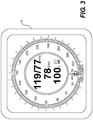
- FIG. 3 illustrates another embodiment of a module associated with the system of FIG. 1 .
- FIG. 4 illustrates a further embodiment of a module associated with the system of FIG. 1 .
- FIG. 5 illustrates a flow chart showing an exemplary method of the present disclosure.
- FIG. 1 illustrates a monitoring system 10 according to an exemplary embodiment of the present disclosure.
- System 10 can be configured to monitor a patient 14 , and in some embodiments, to determine a hemodynamic parameter of the patient 14 .
- System 10 can include a cuff 12 configured to at least to partially occlude the movement of blood through a vessel, vein, and/or artery 22 of the patient 14 .
- cuff 12 can be configured to completely occlude an artery 22 of patient 14 , and the artery 22 may be, for example, the brachial artery.
- the cuff 12 may be inflated to any known occlusion pressure, and at such an occlusion pressure, the artery 22 may be at least partially occluded.
- the cuff 12 may also be deflated to a deflated pressure below (i.e., less than) the occlusion pressure, and at such a pressure, the artery 22 may be substantially unoccluded.
- a deflated pressure below (i.e., less than) the occlusion pressure, and at such a pressure, the artery 22 may be substantially unoccluded.
- cuff 12 may be adapted for placement on any suitable portion of the patient's body, including, for example, a wrist, a finger, an upper thigh, or an ankle.
- one or more cuffs 12 could be placed at different locations about and/or on patient 14 for use with system 10 .
- the exemplary cuffs 12 of the present disclosure may be formed from any medically approved material known in the art. Such materials may be highly flexible, durable, and suitable for contact with, for example, the skin of the patient 14 . Such materials may also be tear-resistant, fluid-impermeable, and recyclable. Such materials may include, for example, paper, cloth, mesh and/or polymers such as polypropylene or polyethylene. In still further exemplary embodiments, such materials may be coated and/or otherwise treated with one or more additives that cause the material to become biodegradable within a desired time interval (e.g., within 2 to 3 months). Each of the exemplary cuffs 12 described herein may have a respective length, width, and inflated height suitable for use with a particular patient 14 .
- a first cuff 12 intended to be used with an adolescent patient 14 may have a first deflated length and a first deflated width
- a second cuff 12 intended for use with an adult patient 14 may have a corresponding second deflated length and second deflated width.
- the first deflated length may be less than the second deflated length
- the first deflated width may be less than the second deflated width.
- inflated lengths and widths of the exemplary cuffs described herein may be different than the corresponding deflated lengths and widths.
- the cuff 12 may include one or more bladders (not shown) or other like inflatable devices. Such a bladder may be formed from a single piece of material or, alternatively, from two or more pieces of material that are joined together through heat sealing, ultrasonic or RF welding, adhering, and/or other like processes. In still further exemplary embodiments, the cuff 12 may form one or more inflatable pockets that perform the same functions as a bladder. In such exemplary embodiments, the bladder may be omitted. It is understood that the cuff 12 and/or bladder may be inflatable to an occlusion pressure of approximately 160 mm Hg or greater to assist in at least partially occluding the artery 22 . In exemplary embodiments, the cuff 12 may include one or more ports (not shown) fluidly connected to the internal pocket or bladder to assist with inflation and/or deflation thereof.
- the pressure or volume of fluid within cuff 12 may be controlled by one or more cuff controllers fluidly connected and/or otherwise operably associated with the cuff 12 .
- the system 10 may include an automatic cuff controller 16 and a manual cuff controller 32 , and both cuff controllers 16 , 32 may be fluidly connected to cuff 12 for inflation and/or deflation thereof.
- one or both cuff controllers 16 , 32 may be releasably and/or otherwise removably fluidly connected to cuff 12 via separate respective ports.
- both cuff controllers 16 , 32 may be fluidly connected to cuff 12 simultaneously (i.e., at the same time).
- cuff 12 may include a single connection port by which cuff controllers 16 , 32 may be separately connected thereto.
- one or both cuff controllers 16 , 32 may be permanently connected to cuff 12 .
- a tube, hose, or other like fluid channel may be integrally connected with, for example, the bladder of cuff 12 .
- Automatic cuff controller 16 can include a pump or similar device configured to inflate and/or deflate the cuff 12 .
- automatic cuff controller 16 could supply cuff 12 with a fluid such as air to increase the pressure or volume within cuff 12 .
- cuff controller 16 could include mechanical, electrical, or chemical devices configured to control occlusion of artery 22 via cuff 12 .
- Automatic cuff controller 16 may be mechanically, fluidly, and/or operably connectable to one or more of the ports described herein to assist in inflating and/or deflating cuff 12 .
- Automatic cuff controller 16 may also be operatively connected and/or otherwise in communication with a cuff control module 20 of system 10 . In such embodiments, automatic cuff controller 16 may be configured to selectively inflate and deflate the cuff 12 in response to one or more control signals received from the cuff control module 20 .
- Cuff control module 20 will be described in greater detail below.
- automatic cuff controller 16 can generally maintain cuff 12 at about a target or reference pressure. For example, once a target or reference pressure has been chosen, automatic cuff controller 16 could inflate and maintain cuff 12 to the target or reference pressure. While the present disclosure refers to a target or reference pressure, it should be understood that the actual pressure applied by cuff 12 may vary slightly from the target or reference. For example, the actual pressure applied to patient 14 may generally remain within appropriate limits, such as, for example, within 2%, 5%, 10%, or 20% of the target or reference pressure. This difference between the chosen target or reference pressure and the actual pressure applied by cuff 12 may be caused by the occlusion efficiency of the respective cuff 12 .
- a cuff's “occlusion efficiency” may be defined as the ease or difficulty with which air pressure within the cuff 12 is transferred to force on the underlying artery 22 .
- cuffs 12 having a higher occlusion efficiency may be capable of applying a relatively greater force to such an artery 22 at a given inflation pressure than a like cuff 12 having a relatively lower occlusion efficiency.
- Manual cuff controller 32 may also be configured to selectively inflate and deflate cuff 12 , and to thereby substantially occlude and unocclude artery 22 , in ways similar to automatic cuff controller 16 .
- manual cuff controller 32 may be hand and/or otherwise manually operated by a user of system 10 to inflate and deflate cuff 12 .
- Manual cuff controller 32 may comprise any manually-operated device configured to supply fluid to and release fluid from cuff 12 .
- manual cuff controller 32 may comprise a manually operated bulb, pump, or other like device commonly associated with conventional manual sphygmomanometers.
- manual cuff controller 32 may also include one or more valves (not shown) or other like flow control devices configured to maintain fluid, such as air, within cuff 12 during inflation thereof, and to facilitate the gradual release of such fluid from cuff 12 during deflation.
- the valve may be manually controlled by the user to regulate the flow of air into and out of cuff 12 during, for example, auscultation.
- the valve may comprise a manually controlled check valve or other like device.
- manual cuff controller 32 may include one or more triggers 34 depressible by a user of manual cuff controller 32 during auscultation or other like patient monitoring activities.
- Trigger 34 may comprise one or more buttons, switches, knobs, or other like actuatable components of manual cuff controller 32 , and a trigger 34 of the present disclosure may be in communication with and/or otherwise operably connected to cuff control module 20 .
- Trigger 34 may be directly connected to cuff control module 20 and/or may be connected thereto via manual cuff controller 32 .
- a user may depress, turn, manipulate, and/or otherwise actuate trigger 34 during auscultation and upon hearing or determining an event.
- a user may actuate trigger 34 upon hearing Korotkoff sounds associated with a systolic pressure and a diastolic pressure of patient 14 .
- trigger 34 and/or manual cuff controller 32 may generate one or more signals indicative of such an event, and such signals may be directed to cuff control module 20 and/or other components of system 10 .
- trigger 34 may be associated with the valve discussed above.
- manual cuff controller 32 may include a valve having a trigger 34 .
- Such a valve may be configured to release air from cuff 12 and, upon hearing Korotkoff sounds associated with a systolic pressure and/or a diastolic pressure of patient 14 , a user of manual cuff controller 32 may actuate the trigger 34 associated with such a valve to indicate that such sounds have been heard.
- System 10 can further include a sensor 18 configured to receive a signal associated with patient 14 , automatic cuff controller 16 , manual cuff controller 32 , and/or cuff control module 20 .
- sensor 18 may determine one or more characteristics associated with artery 22 of patient 14 . Such characteristics may include, for example, a systolic pressure, a diastolic pressure, a mean arterial pressure, and/or other known characteristics associated with cuff 12 , artery 22 , and/or patient 14 .
- sensor 18 may be configured to determine one or more of an oscillation signal strength, an ambient temperature, a humidity, a cumulative cycle count of cuff 12 , a volume of cuff 12 , an occlusion pressure of cuff 12 , a cumulative time associated with cuff 12 being inflated to a reference volume and/or pressure, and/or other like characteristics.
- the reference pressure may be approximately 100 mm Hg, and the target pressure may be equal to the reference pressure.
- the reference volume may be any volume of cuff 12 and/or the bladder associated with reaching such a reference pressure.
- the sensor 18 may comprise devices including, but not limited to, one or more of a pressure sensor, a thermometer, a thermocouple, a hygrometer, and/or a timer.
- the sensor 18 may be located at positions including, but not limited to, within, on, or about cuff 12 .
- System 10 may further include a plurality of sensors 18 , and may include a high-resolution sensor or pneumatic sensor designed to operate in conjunction with cuff 12 .
- sensor 18 can be configured to receive a signal associated with an at least partially occluded artery 22 of patient 14 .
- Such an input signal can arise from blood movement through a partially occluded artery 22 or from a signal associated with an occluded blood vessel.
- Sensor 18 could sample various aspects or characteristics of artery 22 multiple times at various intervals.
- sensor 18 could provide an indication of blood vessel movement, such as, for example, oscillations arising from vascular expansion or contraction. Such oscillations may produce a signal that is detected by sensor 18 , and the strength of such an oscillation signal may be used to determine a hemodynamic parameter of the patient 14 .
- sensor 18 could be configured to detect an occlusion pressure or volume of cuff 12 that may vary periodically with the cyclic expansion and contraction of the artery 22 of patient 14 .
- sensor 18 may be configured to read, scan, sense, detect, and/or otherwise input information associated with cuff 12 .
- information may include, for example, an occlusion efficiency that is particular to the actual cuff 12 being used, or an occlusion efficiency associated with the type, size, design, model, and/or style of cuff 12 being used. It is understood that the type, size, design, model, and/or style of cuff 12 may be characteristics that are unique or particular to the actual cuff 12 being used.
- such characteristics may include and/or may be indicative of the length, width, inflated height, and/or other dimensions of the cuff 12 , the shape of cuff 12 , the number of bladders included in cuff 12 , the length, width, and/or inflated height of such bladders, the maximum inflated volume of cuff 12 , materials used to construct cuff 12 , and whether cuff 12 is intended for use with a child, adolescent, adult, elderly, and/or bariatric patient 14 , among other things.
- sensor 18 may comprise an RFID reader, a barcode reader, an MICR reader, a conductance sensor, a resistance sensor, a magnetic sensor, and/or any other like reading device known in the art.
- Such a sensor 18 may be configured to sense, scan, detect, and/or otherwise read information carried by one or more information features 26 associated with cuff 12 .
- information features 26 may comprise one of an RFID tag, a barcode, MICR printing, a conductive, resistive, and/or magnetic strip of material, and/or other known means for providing information.
- information features 26 may communicate an occlusion efficiency of cuff 12 to the sensor 18 and/or to a user of the system 10 .
- Such information features 26 may also communicate an identification parameter particular to cuff 12 .
- Such an identification parameter may be indicative of, for example, the type, size, design, model, and/or style of cuff 12 being used.
- Such an identification parameter may also comprise, for example, a serial number, a model number, a part number, and/or any other like information enabling the particular cuff 12 to be identified for purposes of tracking or recording, for example, a cumulative cycle count, an age of the cuff, and/or any of the other characteristics described herein.
- One or more such information features 26 may be disposed on an outer exposed surface of cuff 12 for reading by sensor 18 or, alternatively, may be embedded within and/or formed integrally with cuff 12 . Alternatively, in further embodiments, such information features 26 may be omitted.
- Sensor 18 can further be configured to generate one or more output signals indicative of each respective characteristic that is determined.
- the output signal may be generated based on and/or otherwise in response to an input signal received from patient 14 .
- the output signal generated by sensor 18 may be generated in response to activation of trigger 34 , in response to a control signal received from automatic cuff controller 16 , and/or in response to a control signal received from cuff control module 20 .
- sensor 18 may be configured to, in response to activation of trigger 34 , determine a characteristic associated with an at least partially occluded artery 22 , and to generate an output signal indicative of the characteristic.
- Sensor 18 may also be configured to, in response to a control signal received from cuff control module 20 , determine a characteristic associated with an at least partially occluded artery 22 , and to generate an output signal indicative of the characteristic.
- a hemodynamic parameter can include any indication of cardiac or vascular health, such as, for example, an indication of cardiac, circulatory, or vascular functionality.
- a hemodynamic parameter can include a heart rate, a blood pressure, a vessel compliance, an aortic index, an augmentation index, a reflected wave ratio, and/or an indication of treatment.
- a blood pressure can include systolic pressure, diastolic pressure, and/or mean arterial pressure
- vessel compliance may include, for example, arterial stiffness.
- An indication of treatment can include a parameter reflecting the effect of a drug treatment, or one or more treatments of a disease state. It is understand that a hemodynamic parameter may comprise one or more characteristics the artery 22 and vice versa. Accordingly, in exemplary embodiments, and as described herein, the terms “hemodynamic parameter” and “characteristic” may be used interchangeably where applicable.
- a hemodynamic parameter can be determined based on a suprasystolic measurement. In other embodiments, a hemodynamic parameter can be determined based on a first set of data obtained during inflation of cuff 12 and a second set of data obtained during general maintenance of cuff 12 at about a target or reference pressure. Such a target or reference pressure may be, for example, an occlusion pressure wherein the artery 22 is at least partially occluded.
- the first or second sets of data can include various data associated with a signal waveform associated with patient 14 and/or cuff 12 , and may include oscillation signal strength, amplitude, frequency, morphology, feature, or mathematically derived data.
- Data may be derived from a derivative, integration, or frequency analysis, such as, for example, a fast-Fourier transform. Data may also be derived from various algorithms, including curve fitting, a neural network, filtering, smoothing, or data processing. It is understood that the system 10 may comprise any known oscillometric or auscultation system, and that the system 10 may be configured to perform and/or otherwise employ any known oscillometric or auscultation methods.
- cuff 12 , cuff controllers 16 , 32 , and sensor 18 may be operably associated with a cuff control module 20 .
- cuff control module 20 could include one or more processors 28 configured to control one or more operations of cuff 12 , cuff controller 16 , and/or sensor 18 .
- cuff control module 20 can control programmed and/or otherwise automatic inflation and/or deflation of cuff 12 via control of cuff controller 16 .
- Cuff control module 20 and/or one or more processor 28 associated therewith may be configured to, for example, receive the output signals generated by sensor 18 and/or trigger 34 .
- Cuff control module 20 and/or processor 28 may be configured to determine a hemodynamic parameter of patient 14 based on, for example, the one or more output signals of sensor 18 . As described above, one or more such signals may be generated by sensor 18 in response to actuation of trigger 34 . One or more such signals may also be generated by sensor 18 in response to control signals received from cuff control module 20 and/or automatic cuff controller 16 .
- cuff control module 20 may control inflation of cuff 12 to the occlusion pressure described herein, and may maintain inflation of cuff 12 at about the occlusion pressure for a predetermined period of time.
- cuff control module 20 could control inflation of cuff 12 to a calculated, selected, or predetermined occlusion pressure.
- Cuff control module 20 could then generally maintain cuff 12 at about the occlusion pressure for a defined time period, such as, for example, less than about 10 seconds.
- Cuff control module 20 may then control deflation of cuff 12 while directing sensor 18 to determine one or more characteristics of artery 22 .
- the occlusion pressure could be generally maintained for a defined number of cycles, such as, for example, six, eight, or ten cycles, and cuff control module 20 may pause such automatic inflation and deflation of cuff 12 for a predetermined time interval between cycles.
- Information obtained by sensor 18 during such cycles may be used to determine, for example, a mean blood pressure, a heart rate, an arterial stiffness, or other like hemodynamic parameters of patient 14 .
- cuff control module 20 and/or processor 28 may include a signal analysis module 30 configured to analyze one or more signals received from sensor 18 and/or other inputs.
- signal analysis module 30 can include one or more filters configured to filter a signal associated with sensor 18 or cuff control module 20 .
- filters can include band-pass, high-pass, or low-pass filters.
- signal analysis module 30 may assist in determining the hemodynamic parameter of the patient 14 .
- Cuff control module 20 may also include a mode selector 38 operably connected to processor 28 and/or signal analysis module 30 .
- Mode selector 38 may comprise any known knob, switch, dial, button, or other like input device configured to enable a user of system 10 to select between one or more operating modes of system 10 .
- mode selector 38 may enable a user to select between an automatic operating mode in which sensor 18 determines a characteristic of artery 22 in response to a cuff control signal generated by and/or received from cuff control module 20 , and a manual operating mode in which sensor 18 determines a characteristic of artery 22 in response to manual actuation of trigger 34 .
- the automatic operating mode may be characterized by substantially fully-automatic operation of system 10 .
- the user may enter, program, and/or otherwise select one or more parameters of operation, and system 10 may automatically determine one or more characteristics associated artery 22 based on the selected parameters.
- Such parameters may include, for example, at least one of a rate of inflation of cuff 12 , a rate of deflation of cuff 12 , a quantity of artery occlusion cycles, and a time interval between cycles.
- the manual operating mode may be characterized by substantially fully-manual operation of system 10 .
- the user may manually inflate cuff 12 using manual cuff controller 32 , may utilize a stethoscope or other like device to observe Korotkoff sounds associated with artery 22 , and may manually actuate trigger 34 upon hearing such sounds.
- the user may also manually control the rate of inflation and/or deflation of cuff 12 using the valve associated with trigger 34 .
- the user may utilize automatic cuff controller 16 to aid in inflation and/or deflation of cuff 12 .
- one of inflation and deflation of cuff 12 may be performed automatically in response to one or more cuff control signals generated by cuff control module 20 , and the other of inflation and deflation of cuff 12 may be performed manually using manual cuff controller 32 .
- Such an exemplary manual operating mode may be helpful for users with arthritis, carpal tunnel syndrome, or other ailments hindering the user's ability to manually inflate and/or deflate cuff 12 using manual cuff controller 32 .
- mode selector 38 may enable a user to select between the automatic operating mode, the manual operating mode, and a hybrid operating mode.
- a hybrid operating mode may be substantially similar to the exemplary manual operating mode described above in which one of inflation and deflation of cuff 12 may be performed automatically in response to one or more cuff control signals generated by cuff control module 20 , and the other of inflation and deflation of cuff 12 may be performed manually.
- both manual cuff controller 32 and automatic cuff controller 16 may be enabled to inflate and/or deflate cuff 12 , thereby substantially occluding and substantially unoccluding artery 22 .
- system 10 may control automatic cuff controller 16 to automatically inflate and deflate for one or more cycles.
- sensor 18 may make one or a series of automatic characteristic determinations associated with artery 22 .
- a user may manually inflate and deflate cuff 12 using manual cuff controller 32 .
- sensor 18 may also be used to determine characteristics of artery 22 during such manual inflation and deflation of cuff 12 .
- Cuff control module 20 may further include any type of memory (not shown) known in the art.
- memory may comprise random access memory (RAM), read-only memory (ROM), or other types of memory configured to store information associated with the characteristics determined by sensor 18 .
- RAM random access memory
- ROM read-only memory
- Memory of cuff control module 20 may also be configured to store one or more control algorithms associated with system 10 .
- control algorithms may be used by cuff control module 20 to, for example, control operation of automatic cuff controller 16 during one or more of the manual, automatic, and/or hybrid operating modes described herein.
- Such algorithms may also be used by, for example, processor 28 to determine one or more hemodynamic parameters of patient 14 .
- information carried by the output signals generated by sensor 18 may be used as inputs to such algorithms.
- Processor 28 may, thus, utilize such algorithms to determine one or more hemodynamic parameters of patient 14 based on one or more such inputs.
- system 10 can further include a communication module 24 configured to provide communication to patient 14 or one or more users of system 10 .
- communication module 24 could include a monitor, a digital read-out, an analog gauge, dial, or read-out, an LCD screen, or other known device configured to display and/or otherwise output one or more hemodynamic parameters and/or one or more determined characteristics.
- communication module 24 could include a wired, wireless, RF, or other known transmitter configured to transmit data to a remote location.
- Communication module 24 may further include audio output to communicate with patient 14 and/or a user of system 10 .
- FIGS. 2-4 illustrate exemplary communication modules 24 of the present disclosure.
- the configurations of communication modules 24 illustrated in FIGS. 2-4 are merely exemplary, and in further embodiments, more, less, or different information may be displayed and/or otherwise outputted by communication module 24 than that shown in FIGS. 2-4 .
- an exemplary communication module 24 may include an analog dial, a digital dial, and/or other indicator of blood pressure, as measured in millimeters of mercury (mmHg) or other known units.
- communication module 24 may comprise a mercury, jewel, or manual manometer.
- Communication module 24 may also include a digital or other like display such that one or more characteristics determined by sensor 18 may be displayed and/or otherwise outputted thereby. For example, as shown in FIG.
- such a digital display may output a systolic blood pressure and a diastolic blood pressure.
- Such characteristics may be displayed contemporaneously with a corresponding measurement and/or other determination made by sensor 18 .
- such characteristics may be displayed contemporaneously with a corresponding determination made by sensor 18 , and may remain displayed by communication module 24 while a manual determination of blood pressure is made using sensor 18 and/or manual cuff controller 32 .
- a user of system 10 such as a physician, may be able to easily compare an automatic blood pressure determination with a corresponding manual blood pressure determination.
- the various determined characteristics may be outputted simultaneously (i.e., at the same time) by communication module 24 for comparison purposes. It is understood that such simultaneous output by communication module 24 may include displaying a first characteristic, and then displaying a second characteristic, determined later in time, while the first characteristic is displayed.
- communication module 24 may be configured to simultaneously display information indicative of more than one type of determined characteristic.
- communication module 24 may be configured to display information indicative of blood pressure, heart rate (beats per minute), pulse oxidation (percentage), or other like characteristics determined by sensor 18 .
- information may be displayed substantially continuously in applications in which system 10 is used to continuously monitor patient 14 .
- communication module 24 may be configured to simultaneously display information indicative of characteristics obtained through multiple readings, measurements, or other determinations.
- communication module 24 may be configured to display information indicative of a plurality of blood pressures, or other like characteristics, determined by sensor 18 over a series of measurement cycles. Such information displayed by communication module 24 may be determined by sensor 18 as cuff 12 is automatically inflated and/or deflated by automatic cuff controller 16 during the various operating modes described herein. Additionally, communication module 24 may simultaneously display information indicative of one or more blood pressures or other like characteristics determined by sensor 18 as cuff 12 is manually inflated and/or deflated by manual cuff controller 32 during the various operating modes described herein.
- Communication module 24 may also display an icon or other like indicator 36 associated with characteristics determined during such operating modes.
- a visual indicator 36 may enable a user of system 10 to determine, for example, which of the displayed information, characteristics, and/or parameters was obtained during manual operation and which was determined during automatic operation.
- communication module 24 may display such an indicator 36 adjacent information associated with characteristics determined during manual operation of manual cuff controller 32 , such as during a manual operating mode. By displaying indicator 36 adjacent such characteristics, a user may easily distinguish such manually determined characteristic from other simultaneously displayed characteristics determined automatically.
- communication module 24 may also display one or more hemodynamic parameters determined based on the characteristics described herein.
- cuff control module 20 may be configured to determine an average blood pressure of patient 14 based on automatically and manually determined blood pressures, and communication module 24 may be configured to display such an average blood pressure or other like hemodynamic parameters simultaneously with any of the information or characteristics described herein.
- system 10 may include various other components as required, such as, for example, a power source and a user input device.
- One or more components described herein may be combined or may be separate and operate with wireless or wired communication links.
- the various components of system 10 could be integrated into a single unit or assembly, or may operate as separate units or assemblies.
- the cuff control module 20 , automatic cuff controller 16 , processor 28 , sensor 18 , communication module 24 , and/or signal analysis module 30 described herein may be disposed within a single housing, and such a housing may be configured for handheld use.
- manual cuff controller 32 and/or automatic cuff controller 16 may be removably attachable to such a housing.
- manual cuff controller 32 and/or automatic cuff controller 16 may be permanently and/or integrally connected to such a housing.
- methods of monitoring patient 14 and/or determining a hemodynamic parameter of patient 14 may include determining one or more characteristics associated with patient 14 and, in particular, one or more characteristics of artery 22 .
- Such methods may comprise oscillometric methods, auscultation methods, and/or any other known patient monitoring methods.
- such methods may include positioning cuff 12 about a limb of patient 14 (Step: 102 ).
- a substantially deflated cuff 12 may be positioned around a portion of an arm of patient 14 , such as above the elbow (i.e., circumferentially around the bicep and tricep).
- Step: 102 may further include connecting one or both of such components to cuff control module 20 .
- the user may (if not previously or integrally connected) fluidly connect one or both of automatic cuff controller 16 and manual cuff controller 32 to cuff 12 .
- the user may also select an operating mode of system 10 (Step: 104 ) using mode selector 38 of cuff control module 20 .
- mode selector 38 of cuff control module 20 For example, during examination of patient 14 prior to the arrival of a physician, a nurse or other healthcare professional may select either the automatic operating mode or the hybrid operating mode discussed herein.
- Step: 106 cuff control module 20 may direct and/or otherwise control automatic cuff controller 16 to inflate cuff 12 automatically and/or in accordance with a predetermined inflation protocol.
- a predetermined inflation protocol may comprise an algorithm, program, software, or routine stored in memory of cuff control module 20 , and may be executed by processor 28 .
- the user may enter (i.e., select) various parameters of the automatic inflation protocol via communication module 24 and/or cuff control module 20 .
- the user may select one or more of a number of measurement cycles, an interval time between cycles, a cuff inflation rate, a cuff deflation rate, and/or a type or types of characteristics to be measured by sensor 18 during such measurement cycles.
- the user may select such parameters of the inflation protocol using a touch screen, a keyboard, a mouse, one or more buttons, or other like interface components (not shown) of communication module 24 and/or cuff control module 20 .
- sensor 18 may determine the one or more desired characteristics under automatic control of cuff control module 20 (Step: 106 ). For example, sensor 18 may determine one or more characteristics associated with artery 22 while cuff 12 is substantially inflated and in response to control signals sent by cuff control module 20 . It is understood that substantially inflating cuff 12 may substantially occlude artery 22 such that substantially no (i.e., negligible) blood may flow through artery 22 . It is also understood that characteristics determined while artery 22 is in such a substantially occluded state may include a systolic blood pressure, and such a blood pressure may be determined by sensor 18 based on variations in the pressure within cuff 12 .
- cuff control module 20 may automatically inflate cuff 12 to an occlusion pressure that is greater than or equal to a systolic pressure of artery 22 , and sensor 18 may measure and/or otherwise determine oscillations in cuff pressure according to one or more known oscillometric methods. Sensor 18 may generate signals indicative of the determined pressure oscillations and may direct such signals to cuff control module 20 . Cuff control module 20 may utilize such information as inputs to one or more oscillometric pressure algorithms and may determine, for example, a systolic pressure associated with artery 22 based on such information.
- cuff control module 20 may control automatic cuff controller 16 to deflate cuff 12 automatically and/or in accordance with a predetermined deflation protocol similar to the inflation protocol described above. Additionally, at Step: 108 sensor 18 may determine one or more desired characteristics under automatic control of cuff control module 20 . For example, sensor 18 may determine one or more characteristics associated with artery 22 while cuff 12 is substantially deflated and in response to control signals sent by cuff control module 20 . In an exemplary embodiment, cuff control module 20 may automatically deflate cuff 12 to a deflated pressure less than the occlusion pressure, and at such a pressure, blood may resume flow through artery 22 .
- artery 22 may be in a substantially unoccluded state, and as described above with respect to Step: 106 , sensor 18 may measure and/or otherwise determine oscillations in cuff pressure according to one or more known oscillometric methods. Sensor 18 may generate signals indicative of the determined pressure oscillations and may direct such signals to cuff control module 20 . Cuff control module 20 may utilize such information as inputs to one or more oscillometric pressure algorithms and may determine, for example, a diastolic pressure associated with artery 22 based on such information. It is understood that any of the characteristics determined at Step: 106 and Step: 108 may be stored in memory of cuff control module 20 , and may be displayed and/or otherwise outputted by communication module 24 .
- Step: 110 cuff control module 20 may repeat steps Step: 106 and Step: 108 if more than one cycle of measurements was selected or requested by the user at Step: 104 . If more than one automatic measurement cycle was requested by the user at Step: 104 (Step: 110 —Yes), control may return to Step: 106 and the desired number of cycles may be carried out by cuff control module 20 . If, on the other hand, no additional automatic measurement cycles were requested by the user at Step: 104 (Step: 110 —No), control may proceed to Step: 112 where a user, such as a physician, may change or otherwise select an operating mode of system 10 .
- a user such as a physician
- a physician desiring to manually control various operations or components of system 10 may manipulate mode selector 38 to select either the manual operating mode or the hybrid operating mode.
- mode selector 38 may select either the manual operating mode or the hybrid operating mode.
- a physician desiring to manually inflate and/or manually deflate cuff 12 using manual cuff controller 32 may maintain system 10 in the hybrid operating mode, and Step: 112 may be omitted.
- Step: 114 Control may then proceed to Step: 114 and Step: 116 where system 10 may be operated to determine further characteristics of artery 22 .
- the physician may, at Step: 114 , inflate cuff 12 to an occlusion pressure using manual cuff controller 32 .
- the physician may, during Step: 114 , select, for example, one or more of a number of measurement cycles, an interval time between cycles, and a cuff inflation rate as described above with respect to Step: 106 .
- cuff control module 20 may control automatic cuff controller 16 to inflate cuff 12 during Step: 114 .
- cuff control module 20 may control automatic cuff controller 16 to deflate cuff 12 during Step: 116 .
- assistance may be helpful to users of system 10 having difficulty manually inflating or deflating cuff 12 .
- the physician may utilize sensor 18 and trigger 34 to determine one or more characteristics of artery 22 .
- the physician may, using the valve associated with trigger 34 , slowly begin to release air from cuff 12 .
- the physician may listen for Korotkoff sounds indicative of blood beginning to flow through artery 22 using auscultatory methods known in the art. When such Korotkoff sounds are initially heard, the physician may manually actuate trigger 34 , and sensor 18 may, in response, determine one or more desired characteristics associated with artery 22 .
- sensor 18 may determine the pressure associated with artery 22 at the time trigger 34 is actuated. Sensor 18 may then generate a signal indicative of the measured pressure and may direct such a signal to cuff control module 20 .
- Cuff control module 20 may store the determined pressure (i.e., a systolic pressure) in the memory of cuff control module 20 and/or may display the determined pressure via communication module 24 . Since sensor 18 determines the pressure associated with artery 22 at the time trigger 34 is actuated, embodiments of the present disclosure may advantageously avoid the time delay associated with, for example, the physician hearing Korotkoff sounds and responsively looking up to a manometer or other like device to visually observe a corresponding pressure reading.
- the physician may utilize the valve associated with trigger 34 to substantially deflate cuff 12 , thereby substantially unoccluding artery 22 . While continuing to listening for Korotkoff sounds indicative of the resumption of blood flow through artery 22 , the physician may again actuate trigger 34 when no further sounds are heard.
- sensor 18 may again determine one or more desired characteristics associated with artery 22 in response to manual actuation of trigger 34 . For example, sensor 18 may determine the pressure associated with artery 22 at the time trigger 34 is actuated, and may generate a signal indicative of the measured diastolic pressure. Sensor 18 may direct such a signal to cuff control module 20 indicative of the measured diastolic pressure.
- Cuff control module 20 may store the determined pressure in the memory of cuff control module 20 and/or may display the determined pressure via communication module 24 .
- cuff control module 20 may utilize one or more of the characteristics determined at Steps: 106 , 108 , 114 , and 116 to calculate and/or otherwise determine a hemodynamic parameter of patient 14 .
- information indicative of one or more such characteristics may be inputted into an algorithm, routine or program stored in memory of cuff control module 20 , and processor 28 may determine an average blood pressure or other like hemodynamic parameter based on such characteristics.
- one or more algorithms may utilize the determined characteristics described above in combination with one or more empirically derived variables in determining the hemodynamic parameter.
- the variable may be, for example, a scaling factor derived based on test data and/or other information associated with cuff 12 or based on predefined ranges of other parameters such as, for example, systolic and diastolic estimates or the time to inflate cuff 12 .
- a variable may, for example, be derived based on an occlusion efficiency of cuff 12 or other known characteristics of system 10 .
- the variable may scale and/or otherwise affect the hemodynamic parameter determination, and a relatively large variable may result in a correspondingly large adjustment in the determined hemodynamic parameter.
- communication module 24 may output at least one of the characteristics determined at Steps: 106 , 108 , 114 , and 116 .
- communication module 24 may also output one or more of the hemodynamic parameters determined at Step: 118 .
- communication module 24 may simultaneously display the hemodynamic parameter and one or more of the characteristics determined at Steps: 106 , 108 , 114 , and 116 .
- communication module 24 may display indicator 36 identifying which of the plurality of displayed characteristics was determined during the manual, automatic, or hybrid operating mode.
- the accuracy of such a determinations may be improved.
- the methods described herein may reduce the error associated with such hemodynamic parameter determinations such that applicable medical device regulations may be satisfied.
- known auscultation systems require that a physician or other health care provider look up to visually observe a pressure reading as Korotokoff sounds are heard.
- the lag time associated with such systems results in measurement error that can reduce the accuracy of the ultimate hemodynamic parameter determination.
- system 10 facilitates the determination of various characteristics at the instant Korotokoff sounds are heard, the lag time associated with known auscultation systems is avoided. Accordingly, the systems and methods described herein are more accurate and more reliable than existing systems.
- system 10 may comprise any known automated or manual auscultation system.
- system 10 may further include one or more microphones or other like sound sensors configured to sense and/or otherwise detect auscultation signals associated with the artery 22 .
- the methods described herein may be employed by either an oscillometric system or an auscultation system. It is understood that the various method steps described herein, and illustrated in exemplary FIG. 5 , may be performed in any desirable order. It is intended that the specification and examples be considered as exemplary only, with a true scope and spirit of the present disclosure being indicated by the following claims.
Abstract
Description
Claims (28)
Priority Applications (1)
| Application Number | Priority Date | Filing Date | Title |
|---|---|---|---|
| US14/454,225 US11071467B2 (en) | 2013-08-08 | 2014-08-07 | Hybrid patient monitoring system |
Applications Claiming Priority (2)
| Application Number | Priority Date | Filing Date | Title |
|---|---|---|---|
| US201361863817P | 2013-08-08 | 2013-08-08 | |
| US14/454,225 US11071467B2 (en) | 2013-08-08 | 2014-08-07 | Hybrid patient monitoring system |
Publications (2)
| Publication Number | Publication Date |
|---|---|
| US20150045679A1 US20150045679A1 (en) | 2015-02-12 |
| US11071467B2 true US11071467B2 (en) | 2021-07-27 |
Family
ID=52449217
Family Applications (1)
| Application Number | Title | Priority Date | Filing Date |
|---|---|---|---|
| US14/454,225 Active 2037-12-08 US11071467B2 (en) | 2013-08-08 | 2014-08-07 | Hybrid patient monitoring system |
Country Status (1)
| Country | Link |
|---|---|
| US (1) | US11071467B2 (en) |
Families Citing this family (6)
| Publication number | Priority date | Publication date | Assignee | Title |
|---|---|---|---|---|
| CN105943008A (en) * | 2016-03-28 | 2016-09-21 | 上海夏先机电科技发展有限公司 | Portable blood pressure detection apparatus and method thereof for measuring blood pressure |
| DK201600116U4 (en) * | 2016-10-12 | 2017-09-22 | Videnform V/Thomas A Cortebeeck | Equipment for occlusion training |
| US10772571B2 (en) | 2016-11-15 | 2020-09-15 | Welch Allyn, Inc. | Method and systems for correcting for arterial compliance in a blood pressure assessment |
| US10874308B2 (en) * | 2017-09-29 | 2020-12-29 | Fitbit, Inc. | Devices and methods for obtaining pulse information from blood pressure measurements |
| TWI734988B (en) * | 2019-05-24 | 2021-08-01 | 豪展醫療科技股份有限公司 | The blood pressure machine and the blood pressure calculation method used by the blood pressure machine |
| US20210251500A1 (en) * | 2020-02-17 | 2021-08-19 | Zimmer, Inc. | Automatic cuff identification system and method |
Citations (82)
| Publication number | Priority date | Publication date | Assignee | Title |
|---|---|---|---|---|
| US3527204A (en) | 1965-05-28 | 1970-09-08 | Ibm | Pressure cuff system |
| US4313445A (en) | 1977-10-25 | 1982-02-02 | Ivac Corporation | Electronic sphygmomanometer |
| US4367751A (en) | 1976-12-27 | 1983-01-11 | Warner-Lambert Company | Apparatus and process for producing artifact effect on sphygmometric information |
| US4407297A (en) | 1979-08-06 | 1983-10-04 | Medtek Corporation | Method and apparatus for performing non-invasive blood pressure and pulse rate measurements |
| US4493326A (en) | 1979-10-03 | 1985-01-15 | United States Surgical Corporation | Automatic blood pressure system with servo controlled inflation and deflation |
| WO1986003114A1 (en) | 1984-11-27 | 1986-06-05 | University Of North Carolina At Chapel Hill | Portable automated blood pressure monitoring apparatus and method |
| US4617937A (en) | 1985-02-21 | 1986-10-21 | Nippon Colin | Blood pressure monitoring system |
| US4671290A (en) | 1985-01-15 | 1987-06-09 | Richards Medical Company | Automatic tourniquet |
| US4729383A (en) | 1984-12-07 | 1988-03-08 | Susi Roger E | Method and apparatus for automatically determining blood pressure measurements |
| US4796184A (en) | 1986-08-01 | 1989-01-03 | Cas Medical Systems, Inc. | Automatic blood pressure measuring device and method |
| US4889133A (en) | 1988-05-25 | 1989-12-26 | Protocol Systems, Inc. | Method for noninvasive blood-pressure measurement by evaluation of waveform-specific area data |
| US4949710A (en) | 1988-10-06 | 1990-08-21 | Protocol Systems, Inc. | Method of artifact rejection for noninvasive blood-pressure measurement by prediction and adjustment of blood-pressure data |
| US5014714A (en) | 1989-07-19 | 1991-05-14 | Spacelabs, Inc. | Method and apparatus for distinguishing between accurate and inaccurate blood pressure measurements in the presence of artifact |
| US5025791A (en) | 1989-06-28 | 1991-06-25 | Colin Electronics Co., Ltd. | Pulse oximeter with physical motion sensor |
| US5170795A (en) | 1985-07-05 | 1992-12-15 | Critikon, Inc. | Oscillometric blood pressure monitor and method employing non-uniform pressure decrementing steps |
| US5253648A (en) | 1991-10-11 | 1993-10-19 | Spacelabs Medical, Inc. | Method and apparatus for excluding artifacts from automatic blood pressure measurements |
| US5267567A (en) | 1991-07-15 | 1993-12-07 | Colin Electronics Co., Ltd. | Oscillometric-type blood pressure measuring apparatus |
| JPH06133938A (en) | 1992-10-29 | 1994-05-17 | Omron Corp | Electrosphygmomanometer |
| US5339818A (en) | 1989-09-20 | 1994-08-23 | University Of Utah Research Foundation | Method for determining blood pressure utilizing a neural network |
| US5349519A (en) | 1989-09-15 | 1994-09-20 | Hewlett-Packard Company | Method for digitally processing signals containing information regarding arterial blood flow |
| US5348004A (en) | 1993-03-31 | 1994-09-20 | Nellcor Incorporated | Electronic processor for pulse oximeter |
| US5392781A (en) | 1991-04-16 | 1995-02-28 | Cardiodyne, Incorporated | Blood pressure monitoring in noisy environments |
| US5404878A (en) | 1993-01-19 | 1995-04-11 | Hewlett-Packard Company | Method and apparatus for automatic non-invasive monitoring of a patient's blood pressure |
| US5485848A (en) | 1991-01-31 | 1996-01-23 | Jackson; Sandra R. | Portable blood pressure measuring device and method of measuring blood pressure |
| US5577508A (en) | 1995-01-13 | 1996-11-26 | Johnson & Johnson Medical, Inc. | Determination of oscillometric blood pressure by linear approximation |
| US5606977A (en) | 1995-01-04 | 1997-03-04 | Critikon, Inc. | Oscillometric blood pressure monitor which automatically determines when to take blood pressure measurements |
| US5649536A (en) | 1994-02-25 | 1997-07-22 | Colin Corporation | Blood pressure measuring apparatus |
| US5651370A (en) | 1995-02-15 | 1997-07-29 | Johnson & Johnson Medical, Inc. | Detection of oscillometeric blood pressure complexes using correlation |
| JPH1066679A (en) | 1996-08-28 | 1998-03-10 | Omron Corp | Blood pressure monitoring device |
| EP0838194A1 (en) | 1995-03-27 | 1998-04-29 | Colin Corporation | Physical information monitor system having means for indicating amount of deviation of monitored information from normal information |
| US5752919A (en) | 1996-12-17 | 1998-05-19 | Johnson & Johnson Medical, Inc. | Mitigation of respiratory artifact in blood pressure signal using line segment smoothing |
| US5752913A (en) | 1996-09-17 | 1998-05-19 | Colin Corporation | Physical information monitor system having means for determining reference range for abnormality determination of the monitored information |
| JPH10137202A (en) | 1996-11-15 | 1998-05-26 | Omron Corp | Blood pressure calculation device |
| US5758652A (en) | 1995-10-19 | 1998-06-02 | Nikolic; Serjan D. | System and method to measure the condition of a patients heart |
| JPH10151118A (en) | 1996-11-22 | 1998-06-09 | Omron Corp | Electronic blood pressure gauge |
| US5772601A (en) | 1996-08-26 | 1998-06-30 | Colin Corporation | Apparatus for evaluating cardiac function of living subject |
| US5791348A (en) | 1991-03-01 | 1998-08-11 | Colin Electronics Co., Ltd. | Automatic blood pressure measuring system |
| US5836887A (en) | 1996-09-19 | 1998-11-17 | Colin Corporation | Physical information monitor system having means for determining reference range for abnormality determination, based on moving average of previously obtained values |
| US5971932A (en) | 1997-07-18 | 1999-10-26 | Citizen Watch Co., Ltd. | Oscillometric type electronic sphygmomanometer |
| US6083172A (en) | 1995-08-07 | 2000-07-04 | Nellcor Puritan Bennett Incorporated | Method and apparatus for estimating physiological parameters using model-based adaptive filtering |
| US6099476A (en) | 1997-10-15 | 2000-08-08 | W. A. Baum Co., Inc. | Blood pressure measurement system |
| US6168567B1 (en) * | 1998-07-09 | 2001-01-02 | Accusphyg, Llc | Hybrid sphygmomanometer |
| US6196974B1 (en) | 1998-10-07 | 2001-03-06 | Colin Corporation | Blood-pressure monitoring apparatus |
| US6236872B1 (en) | 1991-03-07 | 2001-05-22 | Masimo Corporation | Signal processing apparatus |
| WO2001050952A1 (en) | 2000-01-14 | 2001-07-19 | Microlife Intellectual Property Gmbh | Blood pressure measuring device |
| US6322516B1 (en) | 1998-03-09 | 2001-11-27 | Colin Corporation | Blood-pressure monitor apparatus |
| US6322517B1 (en) * | 1999-04-28 | 2001-11-27 | Omron Corporation | Electronic sphygmomanometer capable of adjusting pressure release rate during measurement |
| US6405076B1 (en) | 1995-09-20 | 2002-06-11 | Protocol Systems, Inc. | Artifact rejector for repetitive physiologic-event-signal data |
| JP2002191568A (en) | 2000-12-25 | 2002-07-09 | Nippon Koden Corp | Graph display method using blood pressure monitor |
| US6428481B1 (en) | 1998-11-27 | 2002-08-06 | Colin Corporation | Blood pressure monitor apparatus |
| US6443905B1 (en) | 1997-09-12 | 2002-09-03 | Polar Electro Oy | Method and arrangement for blood pressure measurement |
| US6500127B1 (en) | 1998-11-27 | 2002-12-31 | Colin Corporation | Blood pressure monitor apparatus |
| US6503206B1 (en) | 2001-07-27 | 2003-01-07 | Vsm Medtech Ltd | Apparatus having redundant sensors for continuous monitoring of vital signs and related methods |
| US6602199B2 (en) * | 1999-06-09 | 2003-08-05 | Vsm Technology Inc. | Method and apparatus for measuring values of physiological parameters |
| US6656116B2 (en) | 2000-09-02 | 2003-12-02 | Samsung Electronics Co. Ltd. | Apparatus and method for perceiving physical and emotional state |
| US20040019284A1 (en) | 2002-07-26 | 2004-01-29 | Colin Corporation | Blood pressure monitor apparatus |
| US20040167411A1 (en) | 2003-02-25 | 2004-08-26 | Ge Medical Systems Information Technologies, Inc. | Oscillometric determination of blood pressure |
| WO2005020808A1 (en) | 2003-08-29 | 2005-03-10 | University Of Warwick | Blood pressure monitor |
| US20060155196A1 (en) * | 2005-01-10 | 2006-07-13 | Maynard Ramsey | Integrated manual mechanical and electronic sphygmomanometer within a single enclosure |
| US20070038129A1 (en) | 2005-08-12 | 2007-02-15 | Omron Healthcare Co., Ltd. | Electronic blood pressure monitor calculating average value of blood pressure |
| WO2007025341A1 (en) | 2005-08-31 | 2007-03-08 | The University Of Queensland | Visual display for blood pressure |
| US20070118036A1 (en) | 2005-11-21 | 2007-05-24 | Hersh Lawrence T | Computation of blood pressure using different signal processing channels |
| US20080119745A1 (en) * | 2006-10-26 | 2008-05-22 | Health & Life Co., Ltd | Manually pressurized electronic sphygmomanometer |
| US20090062664A1 (en) | 2007-08-30 | 2009-03-05 | Fego Precision Industrial Co., Ltd. | Blood pressure measurement device |
| US7515961B2 (en) | 2005-04-29 | 2009-04-07 | Medtronic, Inc. | Method and apparatus for dynamically monitoring, detecting and diagnosing lead conditions |
| US20090312652A1 (en) | 2006-08-03 | 2009-12-17 | Omron Healthcare Co., Ltd. | Electronic manometer for appropriately adjusting internal pressure of cuff and method for controlling the same |
| US20100010356A1 (en) * | 2008-07-09 | 2010-01-14 | Raymond Chan | Blood pressure monitor with remote display |
| US7678060B1 (en) | 2007-03-08 | 2010-03-16 | Millen Ernest W | Method of monitoring a state of health, and a wellness/emotional state monitor implementing the method |
| US20100234742A1 (en) | 2006-01-20 | 2010-09-16 | Microlife Intellectual Property Gmbh | System and Method for Blood Pressure Management |
| US20100331724A1 (en) | 2009-06-30 | 2010-12-30 | Nellcor Puritan Bennett Ireland | Determining a characteristic blood pressure |
| US20110066006A1 (en) | 2009-09-14 | 2011-03-17 | Matt Banet | System for measuring vital signs during hemodialysis |
| US20110077535A1 (en) | 2008-05-27 | 2011-03-31 | Precision Medical Technology Ltd. | Apparatus and method for digital sphygmomanometer |
| US20110092830A1 (en) | 2008-05-27 | 2011-04-21 | Precision Medical Technology Ltd. | method for automatic error detection in pressure measurement and an electronic sphygmomanometer |
| US20110160597A1 (en) | 2009-12-31 | 2011-06-30 | Welch Allyn, Inc. | Suprasystolic Measurement in a Fast Blood-Pressure Cycle |
| US20110218447A1 (en) | 2008-11-20 | 2011-09-08 | Omron Healthcare Co., Ltd. | Electronic sphygmomanometer |
| WO2011110491A1 (en) | 2010-03-09 | 2011-09-15 | Sabirmedical, S.L. | A non-invasive system and method for diagnosing and eliminating white coat hypertention and white coat effect in a patient |
| US8114026B2 (en) | 2009-06-23 | 2012-02-14 | Infarct Reduction Technologies Inc. | Methods and devices for remote ischemic preconditioning and near-continuous blood pressure monitoring |
| US8197416B1 (en) | 2005-08-19 | 2012-06-12 | Ravi Shankar | Pulsatile measurement of cardiac malfunction conditions |
| US20120220884A1 (en) * | 2009-11-11 | 2012-08-30 | Omron Healthcare Co., Ltd. | Electronic sphygmomanometer, control method for electronic sphygmomanometer, and control program for electronic sphygmomanometer |
| US20120226173A1 (en) | 2010-05-25 | 2012-09-06 | Welch Allyn, Inc. | Systems and methods for measuring arterial stiffness |
| US20130261475A1 (en) * | 2004-09-10 | 2013-10-03 | Terumo Kabushiki Kaisha | Sphygmomanometer |
| US20130345576A1 (en) * | 2012-06-20 | 2013-12-26 | National Yang-Ming University | Method for estimating central aortic pulse pressure by cuff pressure pulse wave oscillation signals and device thereof |
-
2014
- 2014-08-07 US US14/454,225 patent/US11071467B2/en active Active
Patent Citations (84)
| Publication number | Priority date | Publication date | Assignee | Title |
|---|---|---|---|---|
| US3527204A (en) | 1965-05-28 | 1970-09-08 | Ibm | Pressure cuff system |
| US4367751A (en) | 1976-12-27 | 1983-01-11 | Warner-Lambert Company | Apparatus and process for producing artifact effect on sphygmometric information |
| US4313445A (en) | 1977-10-25 | 1982-02-02 | Ivac Corporation | Electronic sphygmomanometer |
| US4407297A (en) | 1979-08-06 | 1983-10-04 | Medtek Corporation | Method and apparatus for performing non-invasive blood pressure and pulse rate measurements |
| US4493326A (en) | 1979-10-03 | 1985-01-15 | United States Surgical Corporation | Automatic blood pressure system with servo controlled inflation and deflation |
| WO1986003114A1 (en) | 1984-11-27 | 1986-06-05 | University Of North Carolina At Chapel Hill | Portable automated blood pressure monitoring apparatus and method |
| US4729383A (en) | 1984-12-07 | 1988-03-08 | Susi Roger E | Method and apparatus for automatically determining blood pressure measurements |
| US4671290A (en) | 1985-01-15 | 1987-06-09 | Richards Medical Company | Automatic tourniquet |
| US4617937A (en) | 1985-02-21 | 1986-10-21 | Nippon Colin | Blood pressure monitoring system |
| US5170795A (en) | 1985-07-05 | 1992-12-15 | Critikon, Inc. | Oscillometric blood pressure monitor and method employing non-uniform pressure decrementing steps |
| US4796184A (en) | 1986-08-01 | 1989-01-03 | Cas Medical Systems, Inc. | Automatic blood pressure measuring device and method |
| US4889133A (en) | 1988-05-25 | 1989-12-26 | Protocol Systems, Inc. | Method for noninvasive blood-pressure measurement by evaluation of waveform-specific area data |
| US4949710A (en) | 1988-10-06 | 1990-08-21 | Protocol Systems, Inc. | Method of artifact rejection for noninvasive blood-pressure measurement by prediction and adjustment of blood-pressure data |
| US5025791A (en) | 1989-06-28 | 1991-06-25 | Colin Electronics Co., Ltd. | Pulse oximeter with physical motion sensor |
| US5014714A (en) | 1989-07-19 | 1991-05-14 | Spacelabs, Inc. | Method and apparatus for distinguishing between accurate and inaccurate blood pressure measurements in the presence of artifact |
| US5349519A (en) | 1989-09-15 | 1994-09-20 | Hewlett-Packard Company | Method for digitally processing signals containing information regarding arterial blood flow |
| US5339818A (en) | 1989-09-20 | 1994-08-23 | University Of Utah Research Foundation | Method for determining blood pressure utilizing a neural network |
| US5485848A (en) | 1991-01-31 | 1996-01-23 | Jackson; Sandra R. | Portable blood pressure measuring device and method of measuring blood pressure |
| US5791348A (en) | 1991-03-01 | 1998-08-11 | Colin Electronics Co., Ltd. | Automatic blood pressure measuring system |
| US6236872B1 (en) | 1991-03-07 | 2001-05-22 | Masimo Corporation | Signal processing apparatus |
| US5392781A (en) | 1991-04-16 | 1995-02-28 | Cardiodyne, Incorporated | Blood pressure monitoring in noisy environments |
| US5267567A (en) | 1991-07-15 | 1993-12-07 | Colin Electronics Co., Ltd. | Oscillometric-type blood pressure measuring apparatus |
| US5253648A (en) | 1991-10-11 | 1993-10-19 | Spacelabs Medical, Inc. | Method and apparatus for excluding artifacts from automatic blood pressure measurements |
| JPH06133938A (en) | 1992-10-29 | 1994-05-17 | Omron Corp | Electrosphygmomanometer |
| US5404878A (en) | 1993-01-19 | 1995-04-11 | Hewlett-Packard Company | Method and apparatus for automatic non-invasive monitoring of a patient's blood pressure |
| US5348004A (en) | 1993-03-31 | 1994-09-20 | Nellcor Incorporated | Electronic processor for pulse oximeter |
| US5649536A (en) | 1994-02-25 | 1997-07-22 | Colin Corporation | Blood pressure measuring apparatus |
| US5606977A (en) | 1995-01-04 | 1997-03-04 | Critikon, Inc. | Oscillometric blood pressure monitor which automatically determines when to take blood pressure measurements |
| US5577508A (en) | 1995-01-13 | 1996-11-26 | Johnson & Johnson Medical, Inc. | Determination of oscillometric blood pressure by linear approximation |
| US5651370A (en) | 1995-02-15 | 1997-07-29 | Johnson & Johnson Medical, Inc. | Detection of oscillometeric blood pressure complexes using correlation |
| EP0838194A1 (en) | 1995-03-27 | 1998-04-29 | Colin Corporation | Physical information monitor system having means for indicating amount of deviation of monitored information from normal information |
| US6083172A (en) | 1995-08-07 | 2000-07-04 | Nellcor Puritan Bennett Incorporated | Method and apparatus for estimating physiological parameters using model-based adaptive filtering |
| US6405076B1 (en) | 1995-09-20 | 2002-06-11 | Protocol Systems, Inc. | Artifact rejector for repetitive physiologic-event-signal data |
| US5758652A (en) | 1995-10-19 | 1998-06-02 | Nikolic; Serjan D. | System and method to measure the condition of a patients heart |
| US5772601A (en) | 1996-08-26 | 1998-06-30 | Colin Corporation | Apparatus for evaluating cardiac function of living subject |
| JPH1066679A (en) | 1996-08-28 | 1998-03-10 | Omron Corp | Blood pressure monitoring device |
| US5752913A (en) | 1996-09-17 | 1998-05-19 | Colin Corporation | Physical information monitor system having means for determining reference range for abnormality determination of the monitored information |
| US5836887A (en) | 1996-09-19 | 1998-11-17 | Colin Corporation | Physical information monitor system having means for determining reference range for abnormality determination, based on moving average of previously obtained values |
| JPH10137202A (en) | 1996-11-15 | 1998-05-26 | Omron Corp | Blood pressure calculation device |
| JPH10151118A (en) | 1996-11-22 | 1998-06-09 | Omron Corp | Electronic blood pressure gauge |
| US5752919A (en) | 1996-12-17 | 1998-05-19 | Johnson & Johnson Medical, Inc. | Mitigation of respiratory artifact in blood pressure signal using line segment smoothing |
| US5971932A (en) | 1997-07-18 | 1999-10-26 | Citizen Watch Co., Ltd. | Oscillometric type electronic sphygmomanometer |
| US6443905B1 (en) | 1997-09-12 | 2002-09-03 | Polar Electro Oy | Method and arrangement for blood pressure measurement |
| US6099476A (en) | 1997-10-15 | 2000-08-08 | W. A. Baum Co., Inc. | Blood pressure measurement system |
| US6322516B1 (en) | 1998-03-09 | 2001-11-27 | Colin Corporation | Blood-pressure monitor apparatus |
| US6168567B1 (en) * | 1998-07-09 | 2001-01-02 | Accusphyg, Llc | Hybrid sphygmomanometer |
| US6196974B1 (en) | 1998-10-07 | 2001-03-06 | Colin Corporation | Blood-pressure monitoring apparatus |
| US6428481B1 (en) | 1998-11-27 | 2002-08-06 | Colin Corporation | Blood pressure monitor apparatus |
| US6500127B1 (en) | 1998-11-27 | 2002-12-31 | Colin Corporation | Blood pressure monitor apparatus |
| US6322517B1 (en) * | 1999-04-28 | 2001-11-27 | Omron Corporation | Electronic sphygmomanometer capable of adjusting pressure release rate during measurement |
| US6602199B2 (en) * | 1999-06-09 | 2003-08-05 | Vsm Technology Inc. | Method and apparatus for measuring values of physiological parameters |
| WO2001050952A1 (en) | 2000-01-14 | 2001-07-19 | Microlife Intellectual Property Gmbh | Blood pressure measuring device |
| US6656116B2 (en) | 2000-09-02 | 2003-12-02 | Samsung Electronics Co. Ltd. | Apparatus and method for perceiving physical and emotional state |
| JP2002191568A (en) | 2000-12-25 | 2002-07-09 | Nippon Koden Corp | Graph display method using blood pressure monitor |
| US6503206B1 (en) | 2001-07-27 | 2003-01-07 | Vsm Medtech Ltd | Apparatus having redundant sensors for continuous monitoring of vital signs and related methods |
| US20040019284A1 (en) | 2002-07-26 | 2004-01-29 | Colin Corporation | Blood pressure monitor apparatus |
| US20040167411A1 (en) | 2003-02-25 | 2004-08-26 | Ge Medical Systems Information Technologies, Inc. | Oscillometric determination of blood pressure |
| WO2005020808A1 (en) | 2003-08-29 | 2005-03-10 | University Of Warwick | Blood pressure monitor |
| US20130261475A1 (en) * | 2004-09-10 | 2013-10-03 | Terumo Kabushiki Kaisha | Sphygmomanometer |
| US20060155196A1 (en) * | 2005-01-10 | 2006-07-13 | Maynard Ramsey | Integrated manual mechanical and electronic sphygmomanometer within a single enclosure |
| US8016765B2 (en) | 2005-01-10 | 2011-09-13 | Ramsey Medical Inc. | Integrated manual mechanical and electronic sphygmomanometer within a single enclosure |
| US7515961B2 (en) | 2005-04-29 | 2009-04-07 | Medtronic, Inc. | Method and apparatus for dynamically monitoring, detecting and diagnosing lead conditions |
| US20070038129A1 (en) | 2005-08-12 | 2007-02-15 | Omron Healthcare Co., Ltd. | Electronic blood pressure monitor calculating average value of blood pressure |
| US8197416B1 (en) | 2005-08-19 | 2012-06-12 | Ravi Shankar | Pulsatile measurement of cardiac malfunction conditions |
| WO2007025341A1 (en) | 2005-08-31 | 2007-03-08 | The University Of Queensland | Visual display for blood pressure |
| US20070118036A1 (en) | 2005-11-21 | 2007-05-24 | Hersh Lawrence T | Computation of blood pressure using different signal processing channels |
| US20100234742A1 (en) | 2006-01-20 | 2010-09-16 | Microlife Intellectual Property Gmbh | System and Method for Blood Pressure Management |
| US20090312652A1 (en) | 2006-08-03 | 2009-12-17 | Omron Healthcare Co., Ltd. | Electronic manometer for appropriately adjusting internal pressure of cuff and method for controlling the same |
| US20080119745A1 (en) * | 2006-10-26 | 2008-05-22 | Health & Life Co., Ltd | Manually pressurized electronic sphygmomanometer |
| US7678060B1 (en) | 2007-03-08 | 2010-03-16 | Millen Ernest W | Method of monitoring a state of health, and a wellness/emotional state monitor implementing the method |
| US20090062664A1 (en) | 2007-08-30 | 2009-03-05 | Fego Precision Industrial Co., Ltd. | Blood pressure measurement device |
| US20110092830A1 (en) | 2008-05-27 | 2011-04-21 | Precision Medical Technology Ltd. | method for automatic error detection in pressure measurement and an electronic sphygmomanometer |
| US20110077535A1 (en) | 2008-05-27 | 2011-03-31 | Precision Medical Technology Ltd. | Apparatus and method for digital sphygmomanometer |
| US20100010356A1 (en) * | 2008-07-09 | 2010-01-14 | Raymond Chan | Blood pressure monitor with remote display |
| US20110218447A1 (en) | 2008-11-20 | 2011-09-08 | Omron Healthcare Co., Ltd. | Electronic sphygmomanometer |
| US8114026B2 (en) | 2009-06-23 | 2012-02-14 | Infarct Reduction Technologies Inc. | Methods and devices for remote ischemic preconditioning and near-continuous blood pressure monitoring |
| US20100331724A1 (en) | 2009-06-30 | 2010-12-30 | Nellcor Puritan Bennett Ireland | Determining a characteristic blood pressure |
| US20110066006A1 (en) | 2009-09-14 | 2011-03-17 | Matt Banet | System for measuring vital signs during hemodialysis |
| US20120220884A1 (en) * | 2009-11-11 | 2012-08-30 | Omron Healthcare Co., Ltd. | Electronic sphygmomanometer, control method for electronic sphygmomanometer, and control program for electronic sphygmomanometer |
| US20110160597A1 (en) | 2009-12-31 | 2011-06-30 | Welch Allyn, Inc. | Suprasystolic Measurement in a Fast Blood-Pressure Cycle |
| WO2011110491A1 (en) | 2010-03-09 | 2011-09-15 | Sabirmedical, S.L. | A non-invasive system and method for diagnosing and eliminating white coat hypertention and white coat effect in a patient |
| US20120226173A1 (en) | 2010-05-25 | 2012-09-06 | Welch Allyn, Inc. | Systems and methods for measuring arterial stiffness |
| US20130345576A1 (en) * | 2012-06-20 | 2013-12-26 | National Yang-Ming University | Method for estimating central aortic pulse pressure by cuff pressure pulse wave oscillation signals and device thereof |
| US9510760B2 (en) * | 2012-06-20 | 2016-12-06 | National Yang-Ming University | Method for estimating central aortic pulse pressure by cuff pressure pulse wave oscillation signals and device thereof |
Non-Patent Citations (10)
| Title |
|---|
| Appel et al., Ambulatory Blood Pressure Monitoring and Blood Pressure Self-Measurement in the Diagnosis and Management of Hypertension, Annals of Internal Medicine, Jun. 1, 1993 vol. 118 No. 11, 867-882. |
| Cappuccio et al., A Prospective Study of Hypertension and the Incidence of Kidney Stones in Men, Journal of Hypertension 1999, 17:1017-1022 (6 pages). |
| Elemano digital automatic hybrid blood pressure monitor Source: http://www.ebay.com/itm/ELEMANO-DIGITAL-AUTOMATIC-HYBRID-BLOOD-PRESSURE-MONITOR-/270631061733#vi-content Date Accessed: Sep. 10, 2012. |
| Goonasekera et al., Random Zero Sphygmomanometer Versus Automatic Oscillometric Blood Pressure Monitor; is Either the Instrument of Choice?, Journal of Human Hypertension (1995) 9, 885-889 (5 pages). |
| Kuulasmaa et al., Quality Assessment of Data on Blood Pressure in the Who Monica Project, May 1998, http://www.thl.fi/publications/monica/bp/bpga.htm, Date Accessed: Jul. 12, 2012. |
| Michell, Routine Blood Pressure Measurement: application of the standard canine technique in a human, University of London (Royal Veterinary College), Aug. 1996;1(4):385-387. |
| O'Brien et al., The British Hypertension Society Protocol for the Evaluation of Blood Pressure Measuring Devices, Journal of Hypertension 1993, 11 (suppl 2):543-562 (20 pages). |
| Owens et al., Diagnosis of White Coat Hypertension by Ambulatory Blood Pressure Monitoring, Scientific Contributions, Hypertension, 1999; 34:267-272 (7 pages). |
| Semi-automatic digital blood pressure arm monitor, adult Source: http//www.shop.gorillascientific.com/Semi-Automatic-Digital-Blood-Pressure-Arm-Monitor-Adult-01-5041.htm? gclid=CIWD57_WkrICFWXhQgod4FIAfg Date Accessed: Sep. 10, 2012. |
| Taking an Automated and Manual Blood Pressure Reading with the SunTech 247 Source: http://www.suntechmed.com/support/customer-technical-support/video-tutorials/207-taking-an-automated-and-manual-blood-pressure-reading-with-the-suntech-247 Date Accessed: Sep. 10, 2012. |
Also Published As
| Publication number | Publication date |
|---|---|
| US20150045679A1 (en) | 2015-02-12 |
Similar Documents
| Publication | Publication Date | Title |
|---|---|---|
| US11071467B2 (en) | Hybrid patient monitoring system | |
| US20230052615A1 (en) | Systems and Methods For Monitoring a Patient | |
| US6355000B1 (en) | Superior-and-inferior-limb blood-pressure index measuring apparatus | |
| US10758130B2 (en) | Single site vitals | |
| FI103760B (en) | Method and arrangement for measuring blood pressure | |
| KR100871230B1 (en) | Method and?apparatus for the cuffless and non-invasive device connected to communication device which measures blood pressure from a wrist | |
| KR101798495B1 (en) | Wearable wristwatch-type blood pressure monitor | |
| KR101601421B1 (en) | Method for automatical blood gathering | |
| US10165984B2 (en) | Configurable vital signs system | |
| JP2016507297A (en) | Apparatus, system, and method for monitoring blood pressure | |
| US20190298188A1 (en) | Noninvasive blood pressure measurement method and device | |
| US6099476A (en) | Blood pressure measurement system | |
| US20170360307A1 (en) | Systems and methods for blood pressure measurement | |
| JP2016514983A (en) | Automated assessment of peripheral vascular conditions | |
| US6565515B2 (en) | Pulse-wave-propagation-velocity-relating-information obtaining apparatus and blood-pressure-index measuring apparatus | |
| US20230301529A1 (en) | Continuous blood pressure monitoring | |
| US20150032012A1 (en) | Non-invasive Blood Pressure Measurement System and Methods of Use | |
| KR20100094059A (en) | Apparatus and method for automatic measurement and wireless transmission of blood pressure values based on oscillometric method and k-sound method | |
| Sunitha et al. | Microcontroller based heartbeat, blood pressure, and body temperature monitoring and alerting system using GSM modem | |
| KR20200107157A (en) | Blood Pressure Meter And Method For Measuring Blood Pressure Using The Same | |
| US20230125180A1 (en) | Blood pressure measurement system utilizing auscultatory signal acquisition | |
| WO2013147738A1 (en) | Multi-limb non-invasive blood pressure measurement | |
| KR20190073123A (en) | Portable blood pressure and diabetes meter |
Legal Events
| Date | Code | Title | Description |
|---|---|---|---|
| AS | Assignment |
Owner name: WELCH ALLYN, INC., NEW YORK Free format text: ASSIGNMENT OF ASSIGNORS INTEREST;ASSIGNORS:ST. PIERRE, SHAWN C.;EDWARDS, IAN K.;SIGNING DATES FROM 20140715 TO 20140717;REEL/FRAME:033489/0220 |
|
| AS | Assignment |
Owner name: JPMORGAN CHASE BANK, N.A., AS COLLATERAL AGENT, ILLINOIS Free format text: SECURITY INTEREST;ASSIGNORS:ALLEN MEDICAL SYSTEMS, INC.;HILL-ROM SERVICES, INC.;ASPEN SURGICAL PRODUCTS, INC.;AND OTHERS;REEL/FRAME:036582/0123 Effective date: 20150908 Owner name: JPMORGAN CHASE BANK, N.A., AS COLLATERAL AGENT, IL Free format text: SECURITY INTEREST;ASSIGNORS:ALLEN MEDICAL SYSTEMS, INC.;HILL-ROM SERVICES, INC.;ASPEN SURGICAL PRODUCTS, INC.;AND OTHERS;REEL/FRAME:036582/0123 Effective date: 20150908 |
|
| AS | Assignment |
Owner name: JPMORGAN CHASE BANK, N.A., AS COLLATERAL AGENT, ILLINOIS Free format text: SECURITY AGREEMENT;ASSIGNORS:HILL-ROM SERVICES, INC.;ASPEN SURGICAL PRODUCTS, INC.;ALLEN MEDICAL SYSTEMS, INC.;AND OTHERS;REEL/FRAME:040145/0445 Effective date: 20160921 Owner name: JPMORGAN CHASE BANK, N.A., AS COLLATERAL AGENT, IL Free format text: SECURITY AGREEMENT;ASSIGNORS:HILL-ROM SERVICES, INC.;ASPEN SURGICAL PRODUCTS, INC.;ALLEN MEDICAL SYSTEMS, INC.;AND OTHERS;REEL/FRAME:040145/0445 Effective date: 20160921 |
|
| STPP | Information on status: patent application and granting procedure in general |
Free format text: DOCKETED NEW CASE - READY FOR EXAMINATION |
|
| STPP | Information on status: patent application and granting procedure in general |
Free format text: NON FINAL ACTION MAILED |
|
| AS | Assignment |
Owner name: ANODYNE MEDICAL DEVICE, INC., FLORIDA Free format text: RELEASE BY SECURED PARTY;ASSIGNOR:JPMORGAN CHASE BANK, N.A.;REEL/FRAME:050254/0513 Effective date: 20190830 Owner name: VOALTE, INC., FLORIDA Free format text: RELEASE BY SECURED PARTY;ASSIGNOR:JPMORGAN CHASE BANK, N.A.;REEL/FRAME:050254/0513 Effective date: 20190830 Owner name: MORTARA INSTRUMENT, INC., WISCONSIN Free format text: RELEASE BY SECURED PARTY;ASSIGNOR:JPMORGAN CHASE BANK, N.A.;REEL/FRAME:050254/0513 Effective date: 20190830 Owner name: ALLEN MEDICAL SYSTEMS, INC., ILLINOIS Free format text: RELEASE BY SECURED PARTY;ASSIGNOR:JPMORGAN CHASE BANK, N.A.;REEL/FRAME:050254/0513 Effective date: 20190830 Owner name: HILL-ROM COMPANY, INC., ILLINOIS Free format text: RELEASE BY SECURED PARTY;ASSIGNOR:JPMORGAN CHASE BANK, N.A.;REEL/FRAME:050254/0513 Effective date: 20190830 Owner name: HILL-ROM SERVICES, INC., ILLINOIS Free format text: RELEASE BY SECURED PARTY;ASSIGNOR:JPMORGAN CHASE BANK, N.A.;REEL/FRAME:050254/0513 Effective date: 20190830 Owner name: MORTARA INSTRUMENT SERVICES, INC., WISCONSIN Free format text: RELEASE BY SECURED PARTY;ASSIGNOR:JPMORGAN CHASE BANK, N.A.;REEL/FRAME:050254/0513 Effective date: 20190830 Owner name: WELCH ALLYN, INC., NEW YORK Free format text: RELEASE BY SECURED PARTY;ASSIGNOR:JPMORGAN CHASE BANK, N.A.;REEL/FRAME:050254/0513 Effective date: 20190830 Owner name: HILL-ROM, INC., ILLINOIS Free format text: RELEASE BY SECURED PARTY;ASSIGNOR:JPMORGAN CHASE BANK, N.A.;REEL/FRAME:050254/0513 Effective date: 20190830 |
|
| AS | Assignment |
Owner name: JPMORGAN CHASE BANK, N.A., ILLINOIS Free format text: SECURITY AGREEMENT;ASSIGNORS:HILL-ROM HOLDINGS, INC.;HILL-ROM, INC.;HILL-ROM SERVICES, INC.;AND OTHERS;REEL/FRAME:050260/0644 Effective date: 20190830 |
|
| STPP | Information on status: patent application and granting procedure in general |
Free format text: RESPONSE TO NON-FINAL OFFICE ACTION ENTERED AND FORWARDED TO EXAMINER |
|
| STPP | Information on status: patent application and granting procedure in general |
Free format text: FINAL REJECTION MAILED |
|
| STPP | Information on status: patent application and granting procedure in general |
Free format text: ADVISORY ACTION MAILED |
|
| STPP | Information on status: patent application and granting procedure in general |
Free format text: DOCKETED NEW CASE - READY FOR EXAMINATION |
|
| STPP | Information on status: patent application and granting procedure in general |
Free format text: RESPONSE TO NON-FINAL OFFICE ACTION ENTERED AND FORWARDED TO EXAMINER |
|
| STPP | Information on status: patent application and granting procedure in general |
Free format text: FINAL REJECTION MAILED |
|
| STPP | Information on status: patent application and granting procedure in general |
Free format text: RESPONSE AFTER FINAL ACTION FORWARDED TO EXAMINER |
|
| STPP | Information on status: patent application and granting procedure in general |
Free format text: NOTICE OF ALLOWANCE MAILED -- APPLICATION RECEIVED IN OFFICE OF PUBLICATIONS |
|
| STPP | Information on status: patent application and granting procedure in general |
Free format text: PUBLICATIONS -- ISSUE FEE PAYMENT RECEIVED |
|
| STPP | Information on status: patent application and granting procedure in general |
Free format text: PUBLICATIONS -- ISSUE FEE PAYMENT VERIFIED |
|
| STCF | Information on status: patent grant |
Free format text: PATENTED CASE |
|
| AS | Assignment |
Owner name: HILL-ROM HOLDINGS, INC., ILLINOIS Free format text: RELEASE OF SECURITY INTEREST AT REEL/FRAME 050260/0644;ASSIGNOR:JPMORGAN CHASE BANK, N.A.;REEL/FRAME:058517/0001 Effective date: 20211213 Owner name: BARDY DIAGNOSTICS, INC., ILLINOIS Free format text: RELEASE OF SECURITY INTEREST AT REEL/FRAME 050260/0644;ASSIGNOR:JPMORGAN CHASE BANK, N.A.;REEL/FRAME:058517/0001 Effective date: 20211213 Owner name: VOALTE, INC., FLORIDA Free format text: RELEASE OF SECURITY INTEREST AT REEL/FRAME 050260/0644;ASSIGNOR:JPMORGAN CHASE BANK, N.A.;REEL/FRAME:058517/0001 Effective date: 20211213 Owner name: HILL-ROM, INC., ILLINOIS Free format text: RELEASE OF SECURITY INTEREST AT REEL/FRAME 050260/0644;ASSIGNOR:JPMORGAN CHASE BANK, N.A.;REEL/FRAME:058517/0001 Effective date: 20211213 Owner name: WELCH ALLYN, INC., NEW YORK Free format text: RELEASE OF SECURITY INTEREST AT REEL/FRAME 050260/0644;ASSIGNOR:JPMORGAN CHASE BANK, N.A.;REEL/FRAME:058517/0001 Effective date: 20211213 Owner name: ALLEN MEDICAL SYSTEMS, INC., ILLINOIS Free format text: RELEASE OF SECURITY INTEREST AT REEL/FRAME 050260/0644;ASSIGNOR:JPMORGAN CHASE BANK, N.A.;REEL/FRAME:058517/0001 Effective date: 20211213 Owner name: HILL-ROM SERVICES, INC., ILLINOIS Free format text: RELEASE OF SECURITY INTEREST AT REEL/FRAME 050260/0644;ASSIGNOR:JPMORGAN CHASE BANK, N.A.;REEL/FRAME:058517/0001 Effective date: 20211213 Owner name: BREATHE TECHNOLOGIES, INC., CALIFORNIA Free format text: RELEASE OF SECURITY INTEREST AT REEL/FRAME 050260/0644;ASSIGNOR:JPMORGAN CHASE BANK, N.A.;REEL/FRAME:058517/0001 Effective date: 20211213 |