EP0408967A2 - Sealing body for longitudinally split cable fittings - Google Patents
Sealing body for longitudinally split cable fittings Download PDFInfo
- Publication number
- EP0408967A2 EP0408967A2 EP90112592A EP90112592A EP0408967A2 EP 0408967 A2 EP0408967 A2 EP 0408967A2 EP 90112592 A EP90112592 A EP 90112592A EP 90112592 A EP90112592 A EP 90112592A EP 0408967 A2 EP0408967 A2 EP 0408967A2
- Authority
- EP
- European Patent Office
- Prior art keywords
- sealing body
- pressure plates
- body according
- segments
- dpm1
- Prior art date
- Legal status (The legal status is an assumption and is not a legal conclusion. Google has not performed a legal analysis and makes no representation as to the accuracy of the status listed.)
- Granted
Links
Images


Classifications
-
- H—ELECTRICITY
- H02—GENERATION; CONVERSION OR DISTRIBUTION OF ELECTRIC POWER
- H02G—INSTALLATION OF ELECTRIC CABLES OR LINES, OR OF COMBINED OPTICAL AND ELECTRIC CABLES OR LINES
- H02G15/00—Cable fittings
- H02G15/08—Cable junctions
- H02G15/18—Cable junctions protected by sleeves, e.g. for communication cable
- H02G15/192—Cable junctions protected by sleeves, e.g. for communication cable with support means for ends of the sleeves
-
- H—ELECTRICITY
- H02—GENERATION; CONVERSION OR DISTRIBUTION OF ELECTRIC POWER
- H02G—INSTALLATION OF ELECTRIC CABLES OR LINES, OR OF COMBINED OPTICAL AND ELECTRIC CABLES OR LINES
- H02G15/00—Cable fittings
- H02G15/013—Sealing means for cable inlets
Definitions
- the invention relates to a sealing body for longitudinally divided cable sets made of thermoplastic material with, if necessary, adaptable cable entry openings in the parting plane of the sealing body and with an integrated interception device for the inserted cables.
- sealing bodies for longitudinally divided cable fittings are already known from European patent application EP - 0 219 072. Sealing bodies are used there, which are divided into two equal halves in the direction of insertion. The entries and seals of the cables are carried out in this parting plane, an interception device being additionally arranged.
- This intercepting device essentially consists of two pressure plates which can be moved relative to one another and which likewise have insertion openings corresponding to the insertion openings of the sealing body. However, the pressure plates are arranged a short distance apart when the common insertion openings are cut. If these pressure plates are moved against each other, the not completely closed circular shape of the insertion openings narrows into a kind of almond shape and the clear diameter is thereby narrowed.
- the object of the invention is now to provide sealing bodies with several insertion levels, in which a cable interception direction can be used effectively in all separation levels.
- the stated object is achieved with the aid of a sealing body of the type described at the outset in that the sealing body is divided in the transverse direction into more than two sealing body segments, that the cable entry openings can be cut in each parting plane, that stiffening connecting elements are arranged so as to extend across the parting planes of the sealing body in that In each parting plane, an intercepting device, consisting of two interacting pressure plates guided in chambers of the respective sealing body segments with correspondingly introduced insertion openings, is arranged in such a way that external, inward-acting pressure means for the pressure plates located on the outside are arranged on the connecting elements and that inner, outwards acting pressure medium are arranged for the inner pressure plates guided in the respective middle segments of the sealing body.
- the embodiments according to the invention now have several advantages over the previous state.
- several cables can be inserted through the superimposed parting planes than was previously possible, since there is an overall greater sealing length available for cable entries.
- Due to the multiple division of the sealing body there are considerable difficulties with regard to stability, which are overcome in the embodiments according to the invention in that stiffening connecting elements are used which extend over all parting planes, so that tipping out of individual segments is not possible.
- Due to the design of the invention with regard to the cable clamps in the entrance area a possibility has also been found according to the invention by which it is possible that the inserted cables can also be jammed from the middle segments.
- Figure 1 shows a possibility for the construction of a longitudinally divided cable sleeve KM with, for example, a sealing body DK-Z according to the invention.
- a sealing body DK-E according to the type of the prior art.
- This has a division level HT and is therefore divided into two seal body halves DK-H1 and DK-H2.
- the sealing body DK-Z according to the invention has two parting planes TE1 and TE2, so that three sealing body segments AS1, AS2 and MS are given.
- insertion openings E can now be accommodated in these two parting planes TE1 and TE2 than in the opposite single parting plane HT of the second sealing body DK-E.
- the necessary sealing chambers and wedge chambers are accommodated in the sealing body approaches DK-A, as will be explained below.
- the insertion openings E are cut as required, into which the cables are then inserted and sealed in a manner known per se with an insert made of plastic sealing material.
- the round seal RD is inserted onto the fully assembled sealing bodies DK-E and DK-Z.
- the sleeve pipe with its longitudinal closure LV is then pulled open in a manner known per se, a closure with wedge-shaped beads and a correspondingly adapted wedge rail preferably being used.
- FIG. 2 now shows how the difficulties of a multiple division, in particular here when a sealing body DK-Z is divided into two, are overcome with regard to the strength, in particular the tilting of the relatively narrow sealing body segments.
- stiffening connecting elements VEA1, VEA2 and EM are used here, which interlock and thus extend over the parting planes. These connecting elements are guided closely or even appropriately in the bores of the individual sealing body segments, so that there is a double, continuous stiffening in the sealing body according to the illustration.
- holes are made in the outer segments AS1 and AS2, into which the connecting elements VEA1 and VEA2 are inserted with a protrusion.
- the connecting elements VEA1 or VEA2 now engage when the sealing body segments AS1, AS2 and MS are assembled into connecting elements VEM of the middle segment MS, the bores in the outer segments having a diameter D2 corresponding to the connecting elements VEM, so that the projecting ends of the middle segment therein can be introduced appropriately.
- the inner diameters of the connecting elements VEM are matched to the outer diameters of the connecting elements VEA1 and VEA2 of the outer segments AS1 and AS2, so that the guidance is as free of play as possible. In this way, the mutual stiffening finally results across the parting planes TE1 and TE2.
- protruding screws S then engage in the internal thread DGW of the opposite, inner ends of the connecting elements VEA2.
- the arrangement of the internal threads on the inner ends of the connecting elements VEA2 then additionally ensures that the excess lengths of the screws S required for the preassembly are still within the connecting elements in the final state, so that there are no disruptive projections.
- FIG. 3 shows a section through a sealing body DK-Z with two parting planes TE1 and TE2 according to the invention.
- the circumferential ring groove RN into which sealing material is inserted to seal against the socket pipe.
- the sealing arrangement consisting of individual sealing lips DL one behind the other with sealing cavities DH interposed therebetween, is arranged, with the aid of which sealing in a manner known per se is achieved against the inserted cables.
- a so-called wedge chamber KK1, KK2 and KKM are parallel in each of the three attachment parts DK-A1, DK-A2 and DK-AM arranged running to the sealing cavities DH.
- the pressure plates DP1, DP2, DPM1 and DPM2 are introduced into these wedge chambers, which together with the pressure media DM1, DM2 and DM form the interception device for the inserted cables.
- these pressure plates are each arranged at a suitable distance a from one another on both sides of the parting planes TE1 and TE2.
- the insertion openings E are also cut through the sealing body.
- the outer pressure medium DM1 and Dm2 are designed in particular as a pressure bracket and the inner pressure medium DM in the middle segment MS as a wedge.
- FIG. 4 now shows the preassembly state, as can already be seen in section in FIG. 3.
- this illustration is only a sketch and indicates a view of the attachment side of the sealing body DK-Z, the pressure plates DP1 and DP2 in the outer segments AS1 and AS2 and the pressure plates DPM1 and DPM2 in the middle segment MS in a dotted manner in the position pre-assembly are outlined. It can be seen that a printing plate pair DP1 and DPM1 or DP2 and DPM2 is provided for each parting plane TE1 or TE2.
- the two outer pressure plates DP1 and DP2 can be pressed with the help of external pressure means in a manner known per se with pressure clips in their wedge chamber against the corresponding parting plane. But initially the counter bearing is missing in order to be able to grasp and fix the cable inserted into the insertion opening E all around.
- the inner pressure plates DPM1 and DPM2 indicated there are now pressed outwards in the middle segment MS, preferably with the aid of wedges, as is illustrated in FIG. 5.
- the opposing pressure plates are arranged at a distance a from each other. The size of the distance depends on the type and condition of the cable to be inserted. It should be chosen so that the cable is held non-slip after pressing.
- the cable is constricted all the way down to a depth that depends on the cable construction.
- the insertion of the insertion openings E of the pressure plates is shown in this ten setting, so that the circular cutout height is lower for the pressure plates than for the sealing lips of the sealing body.
- FIG. 5 clearly shows how these different cutout heights of the sealing lips and the pressure plates have an effect on the subsequent fixing of the interception device.
- Wedges K are now driven into these wedge-shaped recesses from the outside, which cause the two pressure plates DPM1 and DPM2 to be pressed outward in the direction of the parting planes TE1 and TE2, as indicated by the double arrows.
- the inserted cables are now also constricted from the inner side and there are almond-shaped enclosures of the cables, as can be seen from the figure.
- This deformation occurs because the insertion openings, which are circular per se, are cut into the pressure plates arranged at a distance a from one another. When moving against each other, there is no longer a complete circular shape.
- this principle can also be implemented by other printing mechanisms, it should always be noted that two printing plates can be moved against each other.
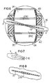
- FIG. 6 now shows one of the various exemplary embodiments according to the invention.
- FIG. 6 shows through a section in the wedge chamber of the sealing body attachment that each of the inner pressure plates DPM1 and DPM2 in the center of the middle segment MS bends in opposite directions on both sides are and that a guide rib FR is arranged between them.
- This guide rib FR divides the two wedge-shaped free spaces between the two inner pressure plates DPM1 and DPM2.
- the free spaces are also designed so that wedges adapted to them can be pressed in from the outside.
- double wedges K are used, which are U-shaped. The coordination between the double wedge K and the guide rib FR takes place in such a way that the guide rib FR is guided between the two legs of the wedge K.
- FIG. 7 shows a U-shaped double wedge K, which on the inside of its legs KS is at least partially provided with teeth Z-KS which run obliquely on one side.
- These teeth Z-KS in interaction with oppositely arranged teeth along the guide rib FR, as shown in FIG. 8, serve as latching elements, thereby preventing the wedge K from being able to loosen again automatically after insertion.
- FIG. 9 shows a constructively designed middle segment MS of a sealing body. At one end stiffeners for the ring groove RN and approximately in the middle the protruding stiffening connecting elements VEM can be seen. Furthermore, the successive sealing cavities DH and the sealing lips DL can be seen in the sectional drawing part, the last cavity being used as a guide chamber KKM for the wedges.
- the guide rib FR is shown running transversely.
- the cutting lines X-X and XI-XI indicate the cutting position for FIGS. 10 and 11.
- FIG. 10 shows that stiffening ribs VR are arranged vertically in the interior of the sealing cavities DH and that the guide rib FR is passed through the entire sealing body. This also serves to stiffen the sealing body.
- FIG. 11 finally shows the section through the wedge chamber KKM of the middle segment MS, so that the course of the guide rib FR becomes clear.
- Gaps KSP are arranged on the side, through which the wedges can be inserted and brought onto the guide rib FR.
Landscapes
- Cable Accessories (AREA)
- Bridges Or Land Bridges (AREA)
- Insulated Conductors (AREA)
- Installation Of Indoor Wiring (AREA)
Abstract
Bei der Erfindung handelt es sich um einen mehrfach geteilten Dichtungskörper (DK-Z) für Kabelmuffen (KM) mit einem einfach geschlitzten Muffenrohr. Die mehrfach geteilten Dichtungskörper (DK-Z) werden mit Hilfe von Versteifungsmitteln (VEA1, VEA2, VEM) über die Trennebenen (TE1, TE2) hinwegstabilisiert. Weiterhin ist eine Kabelabfangvorrichtung angeordnet, die aus Druckplatten (DP1, DP2, DPM1, DM2) gebildet ist, wobei diese Druckplatten in einer Keilkammer (KK1, KK2, KKM) des Dichtungskörpers (DK-Z) geführt werden. Die Fixierung der äußeren Druckplatten (DP1, DP2) erfolgt mit Druckbügeln (DM), die von außen zugänglich sind, während die inneren Druckplatten (DPM1, DMP2) im Mittelsegment (MS) mit Hilfe von eintreibbaren Spreizkeilen (K) in Wirkungslage gebracht werden. 
Description
Die Erfindung betrifft einen Dichtungskörper für längsgeteilte Kabelgarnituren aus thermoplastischem Kunststoff mit bei Bedarf einschneidbaren, anpaßbaren Kabeleinführungsöffnungen in der Trennebene des Dichtungskörpers und mit einer integrierten Abfangvorrichtung für die eingeführten Kabel.The invention relates to a sealing body for longitudinally divided cable sets made of thermoplastic material with, if necessary, adaptable cable entry openings in the parting plane of the sealing body and with an integrated interception device for the inserted cables.
Derartige Dichtungskörper für längsgeteilte Kabelgarnituren sind bereits aus der europäischen Patentanmeldung EP - 0 219 072 bekannt. Dort werden Dichtungskörper verwendet, die in Einführungsrichtung in zwei gleiche Hälften geteilt sind. In dieser Trennungsebene werden die Einführungen und Abdichtungen der Kabel vorgenommen, wobei zusätzlich eine Abfangvorrichtung angeordnet ist. Diese Abfangvorrichtung besteht im wesentlichen aus zwei gegeneinander verschiebbaren Druckplatten, die ebenfalls den Einführungsöffnungen des Dichtungskörpers entsprechende Einführungsöffnungen aufweisen. Die Druckplatten sind jedoch beim Einschneiden der gemeinsamen Einführungsöffnungen in geringem Abstande voneinander angeordnet. Wenn nun diese Druckplatten gegeneinander bewegt werden, verengt sich die nicht völlig geschlossene Kreisform der Einführungsöffnungen in eine Art Mandelform und der lichte Durchmesser wird dadurch verengt. Auf diese Weise wird das eingeführte Kabel eingequetscht und damit zugfest gehalten. Eine derartige Abfangvorrichtung läßt sich jedoch nur bei Dichtungskörperhälften anwenden. Wenn aber eine größere Anzahl von Kabeleinführungen benötigt wird, müssen mehrere Trennebenen vorgesehen werden und damit ergeben sich auch mehrere Dichtungskörpersegmente. Nach der bisherigen Technik ist jedoch eine Kabelabfangung nicht mehr möglich, da bei den mittleren Dichtungskörpersegmenten kein äußerer Eingriff auf die Druckplatten vorhanden ist.Such sealing bodies for longitudinally divided cable fittings are already known from European patent application EP - 0 219 072. Sealing bodies are used there, which are divided into two equal halves in the direction of insertion. The entries and seals of the cables are carried out in this parting plane, an interception device being additionally arranged. This intercepting device essentially consists of two pressure plates which can be moved relative to one another and which likewise have insertion openings corresponding to the insertion openings of the sealing body. However, the pressure plates are arranged a short distance apart when the common insertion openings are cut. If these pressure plates are moved against each other, the not completely closed circular shape of the insertion openings narrows into a kind of almond shape and the clear diameter is thereby narrowed. In this way, the inserted cable is squeezed and thus held tensile. Such an interception device can, however, only be used for sealing body halves. However, if a larger number of cable entries is required, several separation levels must be provided and this also results in several sealing body segments. According to the previous technology, however, cable strain relief is no longer possible, since there is no external interference with the pressure plates in the middle sealing body segments.
Aufgabe der Erfindung ist nun, Dichtungskörper mit mehreren Einführungsebenen zu schaffen, bei denen eine Kabelabfangvor richtung in allen Trennebenen wirksam eingesetzt werden kann. Die gestellte Aufgabe wird mit Hilfe eines Dichtungskörpers der eingangs erläuterten Art dadurch gelöst, daß der Dichtungskörper in Querrichtung in mehr als zwei Dichtungskörpersegmente geteilt ist, daß die Kabeleinführungsöffnungen in jeder Trennebene einschneidbar sind, daß versteifende Verbindungselemente über die Trennebenen des Dichtungskörpers hinwegreichend angeordnet sind, daß in jeder Trennebene eine Abfangvorrichtung, bestehend aus jeweils zwei zusammenwirkenden in Kammern der jeweiligen Dichtungskörpersegmente geführten Druckplatten mit korrespondierend eingebrachten Einführungsöffnungen, angeordnet ist, daß äußere, nach einwärts wirkende Druckmittel für die jeweils außen liegenden Druckplatten an den Verbindungselementen angeordnet sind und daß innere, nach auswärts wirkende Druckmittel für die in den jeweiligen Mittelsegmenten des Dichtungskörpers geführten inneren Druckplatten angeordnet sind.The object of the invention is now to provide sealing bodies with several insertion levels, in which a cable interception direction can be used effectively in all separation levels. The stated object is achieved with the aid of a sealing body of the type described at the outset in that the sealing body is divided in the transverse direction into more than two sealing body segments, that the cable entry openings can be cut in each parting plane, that stiffening connecting elements are arranged so as to extend across the parting planes of the sealing body in that In each parting plane, an intercepting device, consisting of two interacting pressure plates guided in chambers of the respective sealing body segments with correspondingly introduced insertion openings, is arranged in such a way that external, inward-acting pressure means for the pressure plates located on the outside are arranged on the connecting elements and that inner, outwards acting pressure medium are arranged for the inner pressure plates guided in the respective middle segments of the sealing body.
Die Ausführungsformen gemäß der Erfindung haben nun gegenüber dem bisherigen Stand mehrere Vorteile zu verzeichnen. So können durch die übereinander liegenden Trennebenen mehrere Kabel eingeführt werden als es bisher möglich war, da sich insgesamt eine größere für Kabeleinführungen zur Verfügung stehende Dichtungslänge ergibt. Durch die Mehrfachteilung des Dichtungskörpers ergeben sich jedoch bezüglich der Stabilität erhebliche Schwierigkeiten, die bei den Ausführungsformen gemäß der Erfindung dadurch überwunden werden, daß versteifende Verbindungselemente eingesetzt werden, die über alle Trennebenen hinwegreichen, so daß ein Auskippen einzelner Segmente nicht möglich ist. Durch die Ausbildungen der Erfindung bezüglich der Kabelabfangungen im Eingangsbereich ist ebenfalls gemäß der Erfindung eine Möglichkeit gefunden, durch die es ermöglicht wird, daß die eingeführten Kabel auch von den Mittelsegmenten her verklemmt werden können.The embodiments according to the invention now have several advantages over the previous state. Thus, several cables can be inserted through the superimposed parting planes than was previously possible, since there is an overall greater sealing length available for cable entries. Due to the multiple division of the sealing body, there are considerable difficulties with regard to stability, which are overcome in the embodiments according to the invention in that stiffening connecting elements are used which extend over all parting planes, so that tipping out of individual segments is not possible. Due to the design of the invention with regard to the cable clamps in the entrance area, a possibility has also been found according to the invention by which it is possible that the inserted cables can also be jammed from the middle segments.
Die Erfindung wird nun anhand von elf Figuren näher erläutert.
- Figur 1: Kabelmuffe mit einem Dichtungskörper gemäß der Erfindung.
- Figur 2: Dichtungskörper im geöffneten Zustand.
- Figur 3: Dichtungskörper im Querschnitt.
- Figur 4: Schema der Kabelabfangung gemäß der Erfindung im Lieferzustand.
- Figur 5: Schema der Kabelabfangung gemäß der Erfindung im Funktionszustand.
- Figur 6: Eine Ausführungsform der Kabelabfangung mit zwei Keilen entlang einer Führung für die Druckerzeugung.
- Figur 7: Ausführungsform eines Keiles.
- Figur 8: Ausführungsform einer Führungsrippe für die Keile.
- Figur 9: Querschnitt durch ein Mittelsegment.
- Figur 10: Querschnitt durch eine Dichtungskammer eines Mittelsegmentes.
- Figur 11: Querschnitt durch die Keilkammer eines Mittelsegments.
- Figure 1: Cable sleeve with a sealing body according to the invention.
- Figure 2: Seal body in the open state.
- Figure 3: Sealing body in cross section.
- Figure 4: Scheme of cable support according to the invention in the delivery state.
- Figure 5: Scheme of cable support according to the invention in the functional state.
- Figure 6: An embodiment of the cable clamp with two wedges along a guide for pressure generation.
- Figure 7: Embodiment of a wedge.
- Figure 8: Embodiment of a guide rib for the wedges.
- Figure 9: Cross section through a central segment.
- Figure 10: Cross section through a sealing chamber of a central segment.
- Figure 11: Cross section through the wedge chamber of a middle segment.
Die Figur 1 zeigt eine Möglichkeit für den Aufbau einer längsgeteilten Kabelmuffe KM mit zum Beispiel einem Dichtungskörper DK-Z gemäß der Erfindung. Als Beispiel ist aufgezeigt, daß das zweite stirnseitige Ende der Kabelmuffe KM mit einem Dichtungskörper DK-E nach der Art des Standes der Technik versehen ist. Dieser besitzt eine Teilungsebene HT und ist dadurch in zwei Dichtungskörperhälften DK-H1 und DK-H2 geteilt. Der Dichtungskörper DK-Z gemäß der Erfindung besitzt hingegen zwei Trennebenen TE1 und TE2, so daß drei Dichtungskörpersegmente AS1, AS2 und MS gegeben sind. In diesen beiden Trennebenen TE1 und TE2 können nun wie angezeigt ist, wesentlich mehr Einführungsöffnungen E untergebracht werden als in der gegenüberliegenden einzigen Trennebene HT des zweiten Dichtungskörpers DK-E. In den Dichtungskörperansätzen DK-A sind die nötigen Dichtungskammern und Keilkammern untergebracht, wie anschließend noch erläutert wird. So werden nun je nach Bedarf die Einführungsöffnungen E eingeschnitten, in welche dann die Kabel eingeführt und in an sich bekannter Weise mit einer Einlage aus plastischem Dichtungsmaterial abgedichtet werden. Nach der Verklemmung der einzelnen Dichtungskörpersegmente wird die Runddichtung RD auf die fertig montierten Dichtungskörper DK-E und DK-Z eingesetzt. Anschließend wird das Muffenrohr mit seinem Längsverschluß LV in an sich bekannter Weise aufgezogen, wobei vorzugsweise ein Verschluß mit keilförmigen Wulsten und einer entsprechend angepaßten Keilschiene verwendet wird. Durch die Anordnung von Kabeln in verschiedenen Trennebenen des Dichtungskörpers DK-Z können zum Beispiel auch nachträglich zusätzliche Kabel eingeführt werden, ohne daß die bereits bestückte Trennebene Schaden leidet, da diese nicht geöffnet werden muß.Figure 1 shows a possibility for the construction of a longitudinally divided cable sleeve KM with, for example, a sealing body DK-Z according to the invention. As an example it is shown that the second end of the cable sleeve KM is provided with a sealing body DK-E according to the type of the prior art. This has a division level HT and is therefore divided into two seal body halves DK-H1 and DK-H2. The sealing body DK-Z according to the invention, however, has two parting planes TE1 and TE2, so that three sealing body segments AS1, AS2 and MS are given. As indicated, much more insertion openings E can now be accommodated in these two parting planes TE1 and TE2 than in the opposite single parting plane HT of the second sealing body DK-E. The necessary sealing chambers and wedge chambers are accommodated in the sealing body approaches DK-A, as will be explained below. Thus, the insertion openings E are cut as required, into which the cables are then inserted and sealed in a manner known per se with an insert made of plastic sealing material. After the individual sealing body segments have been jammed, the round seal RD is inserted onto the fully assembled sealing bodies DK-E and DK-Z. The sleeve pipe with its longitudinal closure LV is then pulled open in a manner known per se, a closure with wedge-shaped beads and a correspondingly adapted wedge rail preferably being used. By arranging cables in different parting levels of the sealing body DK-Z, additional cables can, for example, also be introduced retrospectively without the parting plane already being damaged, since this does not have to be opened.
Die Figur 2 zeigt nun, wie die Schwierigkeiten über einer Mehrteilung, insbesondere hier bei einer Zweiteilung eines Dichtungskörpers DK-Z bezüglich der Festigkeit, insbesondere des Auskippens der doch relativ schmalen Dichtungskörpersegmente, bewaltigt werden. Gemäß der Erfindung werden hier versteifende Verbindungselemente VEA1, VEA2 und EM verwendet, die ineinandergreifen und die somit über die Trennebenen hinwegreichen. Diese Verbindungselemente sind in Bohrungen der einzelnen Dichtungskörpersegmente eng bzw. sogar passend geführt, so daß sich entsprechend der Abbildung eine zweifache, durchgehende Versteifung im Dichtungskörper ergibt. So werden beispielsweise in den Außensegmenten AS1 und AS2 Bohrungen eingebracht, in welche die Verbindungselemente VEA1 bzw. VEA2 mit Überstand eingesetzt werden. In deren äußeren Enden können zweckmäßigerweise jeweils die Druckmittel in Form von Druckbügeln DM1 bzw. DM2 fest angeordnet werden, so daß sich für jedes Außensegment ein kombiniertes Bauteil ergibt. Die Verbindungselemente VEA1 bzw. VEA2 greifen nun beim Zusammensetzen der Dichtungskörpersegmente AS1, AS2 und MS in ebenfalls überstehende Verbindungselemente VEM des Mittelsegmentes MS ein, wobei die Bohrungen in den Außensegmenten einen den Verbindungselementen VEM entsprechenden Durchmesser D2 aufweisen, so daß die überstehenden Enden des Mittelsegmentes darin passend eingeführt werden können. Die Innendurchmesser der Verbindungselemente VEM sind auf die Außendurchmesser der Verbindungselemente VEA1 und VEA2 der Außensegmente AS1 und AS2 abgestimmt, so daß sich eine möglichst spielfreie Führung ergibt. Auf diese Weise ergibt sich schließlich die gegenseitige Versteifung über die Trennebenen TE1 und TE2 hinweg. Letztlich greifen dann überstehende Schrauben S jeweils im Innengewinde DGW der gegenüberliegenden, inneren Enden der Verbindungselemente VEA2 ein. Auf diese Weise ist erreicht, daß bei der Vormontage die einzelnen Dichtungskörpersegmente in relativ großem Abstand voneinander bereits fixiert werden können, so daß bei der Montage der Kabel zunächst genügend Freiraum gegeben ist. Durch die Anordnung der Innengewinde an den inneren Enden der Verbindungselemente VEA2 wird dann zusätzlich erreicht, daß die für die Vormontage benötigten Überlängen der Schrauben S im Endzustand noch innerhalb der Verbindungselemente liegt, so daß sich keine störenden Überstände ergeben.FIG. 2 now shows how the difficulties of a multiple division, in particular here when a sealing body DK-Z is divided into two, are overcome with regard to the strength, in particular the tilting of the relatively narrow sealing body segments. According to the invention, stiffening connecting elements VEA1, VEA2 and EM are used here, which interlock and thus extend over the parting planes. These connecting elements are guided closely or even appropriately in the bores of the individual sealing body segments, so that there is a double, continuous stiffening in the sealing body according to the illustration. For example, holes are made in the outer segments AS1 and AS2, into which the connecting elements VEA1 and VEA2 are inserted with a protrusion. In the outer ends of the pressure medium in the form of pressure bracket DM1 or DM2 must be arranged so that there is a combined component for each outer segment. The connecting elements VEA1 or VEA2 now engage when the sealing body segments AS1, AS2 and MS are assembled into connecting elements VEM of the middle segment MS, the bores in the outer segments having a diameter D2 corresponding to the connecting elements VEM, so that the projecting ends of the middle segment therein can be introduced appropriately. The inner diameters of the connecting elements VEM are matched to the outer diameters of the connecting elements VEA1 and VEA2 of the outer segments AS1 and AS2, so that the guidance is as free of play as possible. In this way, the mutual stiffening finally results across the parting planes TE1 and TE2. Ultimately, protruding screws S then engage in the internal thread DGW of the opposite, inner ends of the connecting elements VEA2. In this way it is achieved that the individual sealing body segments can already be fixed at a relatively large distance from one another during preassembly, so that there is initially sufficient clearance when installing the cables. The arrangement of the internal threads on the inner ends of the connecting elements VEA2 then additionally ensures that the excess lengths of the screws S required for the preassembly are still within the connecting elements in the final state, so that there are no disruptive projections.
Die Figur 3 zeigt einen Schnitt durch einen Dichtungskörper DK-Z mit zwei Trennebenen TE1 und TE2 gemäß der Erfindung. Man erkennt am einen Ende die umlaufende Ringnut RN, in welche Dichtungsmaterial zur Abdichtung gegen das Muffenrohr eingelegt wird. Im Ansatz dieser Ringnut RN ist die Dichtungsanordnung, bestehend aus einzelnen hintereinander liegenden Dichtungslippen DL mit dazwischen gelagerten Dichtungshohlräumen DH, angeordnet, mit deren Hilfe in an sich bekannter Weise eine Abdichtung gegen die eingeführten Kabel erreicht wird. Zusätzlich sind in den drei Ansatzteilen DK-A1, DK-A2 und DK-AM jeweils noch eine sogenannte Keilkammer KK1, KK2 und KKM parallel verlaufend zu den Dichtungshohlräumen DH angeordnet. In diesen Keilkammern werden die Druckplatten DP1, DP2, DPM1 und DPM2 eingeführt, die zusammen mit den Druckmitteln DM1, DM2 und DM der Abfangvorrichtung für die eingeführten Kabel bilden. Im Zustand der Vormontage sind diese Druckplatten jeweils im geeigneten Abstand a voneinander beidseitig der Trennebenen TE1 bzw. TE2 angeordnet. In diesem Zustand werden auch die Einführungsöffnungen E durch den Dichtungskörper geschnitten. Die äußeren Druckmittel DM1 und Dm2 sind insbesondere als Druckbügel und das innere Druckmittel DM im Mittelsegment MS als Keil ausgebildet.FIG. 3 shows a section through a sealing body DK-Z with two parting planes TE1 and TE2 according to the invention. At one end you can see the circumferential ring groove RN, into which sealing material is inserted to seal against the socket pipe. In the approach of this annular groove RN, the sealing arrangement, consisting of individual sealing lips DL one behind the other with sealing cavities DH interposed therebetween, is arranged, with the aid of which sealing in a manner known per se is achieved against the inserted cables. In addition, a so-called wedge chamber KK1, KK2 and KKM are parallel in each of the three attachment parts DK-A1, DK-A2 and DK-AM arranged running to the sealing cavities DH. The pressure plates DP1, DP2, DPM1 and DPM2 are introduced into these wedge chambers, which together with the pressure media DM1, DM2 and DM form the interception device for the inserted cables. In the state of preassembly, these pressure plates are each arranged at a suitable distance a from one another on both sides of the parting planes TE1 and TE2. In this state, the insertion openings E are also cut through the sealing body. The outer pressure medium DM1 and Dm2 are designed in particular as a pressure bracket and the inner pressure medium DM in the middle segment MS as a wedge.
Die Figur 4 zeigt nun den Vormontagezustand, wie er in Figur 3 bereits im Schnitt zu sehen ist. Diese Darstellung ist der Übersichtlichkeit wegen nur als Skizze ausgeführt und deutet eine Ansicht der Ansatzseite des Dichtungskörpers DK-Z an, wobei die Druckplatten DP1 und DP2 in den Außensegmenten AS1 und AS2 sowie die Druckplatten DPM1 und DPM2 im Mittelsegment MS in punktierter Weise in der Position der Vormontage skizziert sind. Man erkennt dabei, daß für jede Trennebene TE1 bzw. TE2 jeweils ein Druckplattenpaar DP1 und DPM1 bzw. DP2 und DPM2 vorgesehen ist. Die beiden äußeren Druckplatten DP1 und DP2 können mit Hilfe von äußeren Druckmitteln in an sich bekannter Weise mit Druckbügeln in ihrer Keilkammer gegen die entsprechende Trennebene gepreßt werden. Doch fehlt zunächst das Gegenlager, um das in die Einführungsöffnung E eingeführte Kabel rundum fassen und fixieren zu können. Gemäß der Erfindung werden nun im Mittelsegment MS die dort angedeuteten inneren Druckplatten DPM1 und DPM2 nach außen gedrückt und zwar vor zugsweise mit Hilfe von Keilen, wie in Figur 5 verdeutlicht wird. In dieser Figur 4 ist noch ersichtlich, daß die sich gegenüberliegenden Druckplatten im Abstand a voneinander angeordnet sind. Die Größe des Abstandes richtet sich nach der Art und dem Zustand des einzuführenden Kabels. Er soll so gewählt sein, daß das Kabel nach dem Einpressen rutschfest gehalten ist. Dabei wird das Kabel bis zu einer von der Kabelkonstruktion abhängigen Tiefe rundum eingeschnürt. Das Einschneiden der Einführungsöffnungen E der Druckplatten erfolgt in dieser gezeig ten Einstellung, so daß die kreisförmige Ausschnittshöhe bei den Druckplatten jeweils geringer ist als bei den Dichtungslippen des Dichtungskörpers.FIG. 4 now shows the preassembly state, as can already be seen in section in FIG. 3. For the sake of clarity, this illustration is only a sketch and indicates a view of the attachment side of the sealing body DK-Z, the pressure plates DP1 and DP2 in the outer segments AS1 and AS2 and the pressure plates DPM1 and DPM2 in the middle segment MS in a dotted manner in the position pre-assembly are outlined. It can be seen that a printing plate pair DP1 and DPM1 or DP2 and DPM2 is provided for each parting plane TE1 or TE2. The two outer pressure plates DP1 and DP2 can be pressed with the help of external pressure means in a manner known per se with pressure clips in their wedge chamber against the corresponding parting plane. But initially the counter bearing is missing in order to be able to grasp and fix the cable inserted into the insertion opening E all around. According to the invention, the inner pressure plates DPM1 and DPM2 indicated there are now pressed outwards in the middle segment MS, preferably with the aid of wedges, as is illustrated in FIG. 5. In this Figure 4 it can still be seen that the opposing pressure plates are arranged at a distance a from each other. The size of the distance depends on the type and condition of the cable to be inserted. It should be chosen so that the cable is held non-slip after pressing. The cable is constricted all the way down to a depth that depends on the cable construction. The insertion of the insertion openings E of the pressure plates is shown in this ten setting, so that the circular cutout height is lower for the pressure plates than for the sealing lips of the sealing body.
Die Figur 5 zeigt nun deutlich, wie sich diese verschiedenen Ausschnittshöhen der Dichtungslippen und der Druckplatten bei der anschließenden Fixierung der Abfangvorrichtung auswirken. Durch das Anpressen der äußeren Druckplatten DP1 und DP2 innerhalb der Keilkammern der beiden Außensegmente AS1 und AS2 mit Hilfe der beiden Druckmittel DM in Richtung der Pfeile werden die Druckplatten gegen die Trennebenen TE1 und TE2 eingeschoben und der vorherige Abstand a verringert sich. Die beiden innen liegenden Druckplatten DPM1 und DPM2 in der Keilkammer des Mittelsegmentes MS sind auf den sich gegenüberliegenden Seiten gegenläufig abgeschrägt, so daß wie sich bereits aus Figur 4 absehen läßt, beidseitig von der Mittellinie nach außen sich keilförmig erweiternde Aussparungen ergeben. In diese keilförmigen Aussparungen werden nun von außen her Keile K eingetrieben, die bewirken, daß die beiden Druckplatten DPM1 und DPM2 nach auswärts in Richtung der Trennebenen TE1 bzw. TE2 gedrückt werden, wie die Doppelpfeile andeuten. Dadurch werden nun die eingeführten Kabel auch von der inneren Seite her eingeschnürt und es ergeben sich dabei mandelförmige Umfassungen der Kabel, wie es aus der Figur zu ersehen ist. Diese Verformung ergibt sich, da die an sich kreisförmigen Einführungsöffnungen in die im Abstand a voneinander angeordneten Druckplatten eingeschnitten werden. Beim Gegeneinanderverschieben kommt somit keine vollständige Kreisform mehr zustande. Dieses Prinzip kann jedoch auch durch andere Druckmechanismen umgesetzt werden, dabei ist immer zu beachten, daß jeweils zwei Druckplatten gegeneinander verschiebbar sind.FIG. 5 clearly shows how these different cutout heights of the sealing lips and the pressure plates have an effect on the subsequent fixing of the interception device. By pressing the outer pressure plates DP1 and DP2 within the wedge chambers of the two outer segments AS1 and AS2 with the help of the two pressure means DM in the direction of the arrows, the pressure plates are pushed in against the parting planes TE1 and TE2 and the previous distance a is reduced. The two inner pressure plates DPM1 and DPM2 in the wedge chamber of the middle segment MS are beveled in opposite directions on the opposite sides, so that, as can already be seen in FIG. 4, there are wedge-shaped recesses on both sides from the center line to the outside. Wedges K are now driven into these wedge-shaped recesses from the outside, which cause the two pressure plates DPM1 and DPM2 to be pressed outward in the direction of the parting planes TE1 and TE2, as indicated by the double arrows. As a result, the inserted cables are now also constricted from the inner side and there are almond-shaped enclosures of the cables, as can be seen from the figure. This deformation occurs because the insertion openings, which are circular per se, are cut into the pressure plates arranged at a distance a from one another. When moving against each other, there is no longer a complete circular shape. However, this principle can also be implemented by other printing mechanisms, it should always be noted that two printing plates can be moved against each other.
Die Figur 6 zeigt nun eines der vielfältigen Ausführungsbeispiele gemäß der Erfindung. Die Figur 6 läßt durch einen Schnitt in der Keilkammer des Dichtungskörperansatzes erkennen, daß jede der inneren Druckplatten DPM1 und DPM2 im Zentrum des Mittelsegmentes MS nach beidne Seiten hin gegenläufig abgeschragt sind und daß zwischen ihnen eine Führungsrippe FR angeordnet ist. Diese Führungsrippe FR teilt dabei die beiden keilförmigen Freiräume zwischen den beiden inneren Druckplatten DPM1 und DPM2. Die Freiräume sind jedoch außerdem so angelegt, daß darin angepaßte Keile von außen her eingepreßt werden können. In diesem speziellen Ausführungsbeispiel werden Doppelkeile K verwendet, die U-förmig gestaltet sind. Die Abstimmung zwischen dem Doppelkeil K und der Führungsrippe FR erfolgt so, daß die Führungsrippe FR zwischen den beiden Schenkein des Keiles K geführt wird. Dadurch ergibt sich eine gleichmäßige Austreibung der inneren Druckplatten DPM1 und DPM2 nach auswärts. Bei diesem Ausführungsbeispiel werden außerdem zwei derartige Keile verwendet, die gegenüberliegend eingetrieben werden. Die äußeren Druckplatten DP1 und DP2 werden in an sich bekannter Weise mit Hilfe der Druckmittel DM eingepreßt.FIG. 6 now shows one of the various exemplary embodiments according to the invention. FIG. 6 shows through a section in the wedge chamber of the sealing body attachment that each of the inner pressure plates DPM1 and DPM2 in the center of the middle segment MS bends in opposite directions on both sides are and that a guide rib FR is arranged between them. This guide rib FR divides the two wedge-shaped free spaces between the two inner pressure plates DPM1 and DPM2. However, the free spaces are also designed so that wedges adapted to them can be pressed in from the outside. In this special embodiment, double wedges K are used, which are U-shaped. The coordination between the double wedge K and the guide rib FR takes place in such a way that the guide rib FR is guided between the two legs of the wedge K. This results in a uniform expulsion of the inner pressure plates DPM1 and DPM2 outwards. In this embodiment, two such wedges are also used, which are driven in opposite directions. The outer pressure plates DP1 and DP2 are pressed in in a manner known per se using the pressure means DM.
Die Figur 7 zeigt einen U-förmigen Doppelkeil K, der an der Innenseite seiner Schenkel KS zumindest teilweise mit einseitig schräg verlaufenden Zähnen Z-KS versehen ist. Diese Zähne Z-KS dienen im Zusammenspiel mit gegenläufig angeordneten Zähnen entlang der Führungsrippe FR, wie sie in Figur 8 gezeigt wird, als Rastelemente, wodurch vermieden wird, daß sich der Keil K nach dem Einschieben selbsttätig wieder lösen kann.FIG. 7 shows a U-shaped double wedge K, which on the inside of its legs KS is at least partially provided with teeth Z-KS which run obliquely on one side. These teeth Z-KS, in interaction with oppositely arranged teeth along the guide rib FR, as shown in FIG. 8, serve as latching elements, thereby preventing the wedge K from being able to loosen again automatically after insertion.
In Figur 9 wird ein konstruktiv ausgeführtes Mittelsegment MS eines Dichtungskörpers gezeigt. An dem einen Ende sind Versteifungen für die Ringnut RN und etwa in der Mitte die überstehenden versteifenden Verbindungselemente VEM erkennbar. Weiterhin sind im Schnittbildteil die hintereinander liegenden Dichtungshohlräume DH und die Dichtungslippen DL zu sehen, wobei der letzte Hohlraum als Führungskammer KKM für die Keile verwendet wird. Quer verlaufend ist die Führungsrippe FR dargestellt. Die Schnittlinien X-X und XI-XI deuten die Schnittlage für die Figuren 10 und 11 an.FIG. 9 shows a constructively designed middle segment MS of a sealing body. At one end stiffeners for the ring groove RN and approximately in the middle the protruding stiffening connecting elements VEM can be seen. Furthermore, the successive sealing cavities DH and the sealing lips DL can be seen in the sectional drawing part, the last cavity being used as a guide chamber KKM for the wedges. The guide rib FR is shown running transversely. The cutting lines X-X and XI-XI indicate the cutting position for FIGS. 10 and 11.
Die Figur 10 zeigt, daß im Inneren der Dichtungshohlräume DH senkrecht verlaufend Versteifungsrippen VR angeordnet sind und daß die Führungsrippe FR durch den gesamten Dichtungskörper hindurchgeführt ist. Auch dies dient hier zur Versteifung des Dichtungskörpers.FIG. 10 shows that stiffening ribs VR are arranged vertically in the interior of the sealing cavities DH and that the guide rib FR is passed through the entire sealing body. This also serves to stiffen the sealing body.
Die Figur 11 zeigt schließlich den Schnitt durch die Keilkammer KKM des Mittelsegmentes MS, so daß der Verlauf der Führungsrippe FR deutlich wird. Seitlich sind Spalte KSP angeordnet, durch die die Keile eingeführt und auf die Führungsrippe FR gebracht werden können.FIG. 11 finally shows the section through the wedge chamber KKM of the middle segment MS, so that the course of the guide rib FR becomes clear. Gaps KSP are arranged on the side, through which the wedges can be inserted and brought onto the guide rib FR.
Claims (14)
Priority Applications (1)
| Application Number | Priority Date | Filing Date | Title |
|---|---|---|---|
| AT90112592T ATE103117T1 (en) | 1989-07-18 | 1990-07-02 | SEALING BODY FOR SPLIT CABLE ASSEMBLIES. |
Applications Claiming Priority (2)
| Application Number | Priority Date | Filing Date | Title |
|---|---|---|---|
| DE3923762 | 1989-07-18 | ||
| DE3923762 | 1989-07-18 |
Publications (3)
| Publication Number | Publication Date |
|---|---|
| EP0408967A2 true EP0408967A2 (en) | 1991-01-23 |
| EP0408967A3 EP0408967A3 (en) | 1991-10-16 |
| EP0408967B1 EP0408967B1 (en) | 1994-03-16 |
Family
ID=6385301
Family Applications (1)
| Application Number | Title | Priority Date | Filing Date |
|---|---|---|---|
| EP90112592A Expired - Lifetime EP0408967B1 (en) | 1989-07-18 | 1990-07-02 | Sealing body for longitudinally split cable fittings |
Country Status (5)
| Country | Link |
|---|---|
| US (1) | US5006669A (en) |
| EP (1) | EP0408967B1 (en) |
| AT (1) | ATE103117T1 (en) |
| DE (1) | DE59004983D1 (en) |
| ES (1) | ES2050309T3 (en) |
Cited By (8)
| Publication number | Priority date | Publication date | Assignee | Title |
|---|---|---|---|---|
| WO1993003302A1 (en) * | 1991-08-09 | 1993-02-18 | N.V. Raychem S.A. | Technique for sealing |
| DE4333067C1 (en) * | 1993-09-29 | 1995-03-09 | Rose Walter Gmbh & Co Kg | Device for forming a socket inlet, in particular for fiber optic cables |
| WO2001013485A1 (en) * | 1999-08-13 | 2001-02-22 | Rxs Gesellschaft Für Vermögensverwaltung Mbh | Universal cable fitting |
| WO2001041276A3 (en) * | 1999-12-02 | 2001-10-25 | Rxs Kabelgarnituren Gmbh & Co | Sealing body for longitudinally split cable fittings |
| DE4330294C2 (en) * | 1993-09-07 | 2002-10-31 | Rxs Schrumpftech Garnituren | Distribution Closure |
| US6575474B1 (en) | 1998-07-15 | 2003-06-10 | Corning Cable Systems Llc | Sealing element for cable fittings |
| WO2015090907A1 (en) * | 2013-12-19 | 2015-06-25 | Reichle & De-Massari Ag | Sealing module |
| US20220337044A1 (en) * | 2019-09-24 | 2022-10-20 | Commscope Technologies Llc | Composite cable seal |
Families Citing this family (20)
| Publication number | Priority date | Publication date | Assignee | Title |
|---|---|---|---|---|
| US5313019A (en) * | 1988-11-09 | 1994-05-17 | N.V. Raychem S.A. | Closure assembly |
| DE4035557A1 (en) * | 1990-11-08 | 1992-05-14 | Rxs Schrumpftech Garnituren | HOOD SLEEVE |
| GB9112181D0 (en) * | 1991-06-06 | 1991-07-24 | Raychem Sa Nv | Cable sealing |
| US5245133A (en) * | 1991-10-15 | 1993-09-14 | Thomas & Betts Corporation | Moisture-resistant cable splice and sealing structure thereof |
| US5251373A (en) * | 1991-10-15 | 1993-10-12 | Thomas & Betts Corporation | Method for protection of cable splices |
| US5313018A (en) * | 1991-11-22 | 1994-05-17 | Rxs Schrumpftechnik-Garnituren Gmbh | Cable sleeve composed of a longitudinally-divided housing |
| US5498839A (en) * | 1993-05-27 | 1996-03-12 | Rxs Schrumpftechnik-Garnituren Gmbh | Cable sleeve composed of a pipe section and seal members at the face end |
| US5446823A (en) * | 1994-01-26 | 1995-08-29 | Raychem Corporation | Aerial, pedestal, below grade, or buried optical fiber closure |
| US5850056A (en) * | 1996-04-22 | 1998-12-15 | Andrew Corporation | Grounding kit for a transmission line cable including a clip, a bail and a housing |
| FR2759503B1 (en) * | 1997-02-11 | 1999-04-30 | Japan Recom Ltd | CABLE CONNECTION CLOSING MEMBER |
| EP0923178A3 (en) * | 1997-12-09 | 2001-01-03 | RXS Kabelgarnituren Gesellschaft mit beschränkter Haftung | Cable sleeve, comprising a tubular sleeve and at least a transversely split frontal sealing body |
| US6248953B1 (en) * | 1999-02-05 | 2001-06-19 | 3M Innovative Properties Company | Segmented end seal for a closure such as a splice case |
| AU2003900827A0 (en) * | 2003-02-25 | 2003-03-13 | Kevin Dutton | A closure assembly for wire connections |
| AU2004203261B2 (en) * | 2003-02-25 | 2005-05-26 | Kevin Dutton | A process of remaking wire connections |
| US8087977B2 (en) | 2005-05-13 | 2012-01-03 | Black & Decker Inc. | Angle grinder |
| WO2009005416A1 (en) * | 2007-07-05 | 2009-01-08 | Cyrba Ab | Cable fitting arrangement |
| US20170108147A1 (en) * | 2015-10-14 | 2017-04-20 | Daniel L. Cindrich | Means and Methods of Cable Organization |
| DE102020102583A1 (en) * | 2020-02-03 | 2021-08-05 | Reflex Winkelmann Gmbh | Cable entry |
| CN112260203B (en) * | 2020-10-10 | 2022-03-01 | 国网河南省电力公司方城县供电公司 | Anti-blocking electric power tube |
| JP2022099947A (en) * | 2020-12-23 | 2022-07-05 | 株式会社オートネットワーク技術研究所 | Wiring module and elastic cutoff member |
Family Cites Families (7)
| Publication number | Priority date | Publication date | Assignee | Title |
|---|---|---|---|---|
| US3742119A (en) * | 1971-11-11 | 1973-06-26 | Empire Prod Inc | Terminal housing |
| DE7425454U (en) * | 1974-07-25 | 1974-11-07 | Siemens Ag | Lip-shaped sealing body for cable sleeves |
| US4103911A (en) * | 1975-06-06 | 1978-08-01 | Siemens Aktiengesellschaft | Sealing member for cable inlets |
| DE7739190U1 (en) * | 1977-12-22 | 1978-04-06 | Siemens Ag, 1000 Berlin Und 8000 Muenchen | Sealing body for inserting cables into cable fittings |
| DE3036022C2 (en) * | 1980-09-24 | 1982-06-09 | Siemens AG, 1000 Berlin und 8000 München | Sealing body divided into segments for lengthways divided cable fittings |
| FR2582854B1 (en) * | 1985-05-31 | 1988-03-18 | Morel Atel Electromec | SLEEVE FOR PROTECTING CABLE SPLICES AND RELATED METHOD |
| ATE100643T1 (en) * | 1985-10-14 | 1994-02-15 | Siemens Ag | SEALING BODY FOR CABLE ASSEMBLIES MADE OF THERMOPLASTIC PLASTIC. |
-
1990
- 1990-05-25 US US07/528,423 patent/US5006669A/en not_active Expired - Lifetime
- 1990-07-02 EP EP90112592A patent/EP0408967B1/en not_active Expired - Lifetime
- 1990-07-02 DE DE90112592T patent/DE59004983D1/en not_active Expired - Fee Related
- 1990-07-02 ES ES90112592T patent/ES2050309T3/en not_active Expired - Lifetime
- 1990-07-02 AT AT90112592T patent/ATE103117T1/en not_active IP Right Cessation
Cited By (11)
| Publication number | Priority date | Publication date | Assignee | Title |
|---|---|---|---|---|
| WO1993003302A1 (en) * | 1991-08-09 | 1993-02-18 | N.V. Raychem S.A. | Technique for sealing |
| US5560618A (en) * | 1991-08-09 | 1996-10-01 | N.V. Raychem S.A. | Technique for sealing |
| DE4330294C2 (en) * | 1993-09-07 | 2002-10-31 | Rxs Schrumpftech Garnituren | Distribution Closure |
| DE4333067C1 (en) * | 1993-09-29 | 1995-03-09 | Rose Walter Gmbh & Co Kg | Device for forming a socket inlet, in particular for fiber optic cables |
| US6575474B1 (en) | 1998-07-15 | 2003-06-10 | Corning Cable Systems Llc | Sealing element for cable fittings |
| WO2001013485A1 (en) * | 1999-08-13 | 2001-02-22 | Rxs Gesellschaft Für Vermögensverwaltung Mbh | Universal cable fitting |
| WO2001041276A3 (en) * | 1999-12-02 | 2001-10-25 | Rxs Kabelgarnituren Gmbh & Co | Sealing body for longitudinally split cable fittings |
| US6802512B2 (en) | 1999-12-02 | 2004-10-12 | Ccs Technology, Inc. | Sealing body for longitudinally split cable fittings |
| WO2015090907A1 (en) * | 2013-12-19 | 2015-06-25 | Reichle & De-Massari Ag | Sealing module |
| US20220337044A1 (en) * | 2019-09-24 | 2022-10-20 | Commscope Technologies Llc | Composite cable seal |
| US12095244B2 (en) * | 2019-09-24 | 2024-09-17 | Commscope Technologies Llc | Composite cable seal |
Also Published As
| Publication number | Publication date |
|---|---|
| US5006669A (en) | 1991-04-09 |
| DE59004983D1 (en) | 1994-04-21 |
| EP0408967A3 (en) | 1991-10-16 |
| ATE103117T1 (en) | 1994-04-15 |
| ES2050309T3 (en) | 1994-05-16 |
| EP0408967B1 (en) | 1994-03-16 |
Similar Documents
| Publication | Publication Date | Title |
|---|---|---|
| EP0408967B1 (en) | Sealing body for longitudinally split cable fittings | |
| EP1238451B1 (en) | Sealing body for longitudinally split cable fittings | |
| DE2515939C3 (en) | Thermoplastic socket with sealing body | |
| DE3512175C2 (en) | ||
| EP0521324B1 (en) | Cable sleeve | |
| DE9016138U1 (en) | Filter ring | |
| DE2701873B2 (en) | Quick coupling for synthetic resin pipes | |
| DE4434202A1 (en) | Cable lead-through strip | |
| EP0026435A1 (en) | Closing device for cable fittings of heat-shrinkable material | |
| EP3012933A2 (en) | Cable passage seal for a cable duct, construction kit for a cable passage sealing and method for mounting a cable passage seal for a cable duct | |
| EP0543350B1 (en) | Cable sleeve comprising a longitudinally divided housing | |
| EP2614565A2 (en) | Cable bushing | |
| DE2736039B2 (en) | Distribution sleeve based on the thermoplastic clamping sleeve principle | |
| DE60210151T2 (en) | splice protection sleeve | |
| DE3512578C2 (en) | ||
| DE19609709A1 (en) | Electric wall socket,switch-box or branch box | |
| EP0403937B1 (en) | Universal sleeve with longitudinally split sleeve pipe and end sealing bodies | |
| EP2806516A1 (en) | Seal block for individual wires | |
| EP0693638B1 (en) | Chain for carrying an energy line and method of introducing the line in the chain | |
| DE10010452A1 (en) | Sealing body for longitudinally divided cable fittings | |
| DE3127567C2 (en) | Arrangement for sealing cables | |
| EP0638975A1 (en) | Sleeve end with a plurality of split cable inlets | |
| DE2652803B2 (en) | Cable set with lamellar seal | |
| DE9102824U1 (en) | Device for sealing the ends of cable protection pipes | |
| DE10141543B4 (en) | Device for fixing objects on an abutment |
Legal Events
| Date | Code | Title | Description |
|---|---|---|---|
| PUAI | Public reference made under article 153(3) epc to a published international application that has entered the european phase |
Free format text: ORIGINAL CODE: 0009012 |
|
| AK | Designated contracting states |
Kind code of ref document: A2 Designated state(s): AT BE CH DE ES FR GB IT LI NL SE |
|
| 17P | Request for examination filed |
Effective date: 19901205 |
|
| PUAL | Search report despatched |
Free format text: ORIGINAL CODE: 0009013 |
|
| AK | Designated contracting states |
Kind code of ref document: A3 Designated state(s): AT BE CH DE ES FR GB IT LI NL SE |
|
| 17Q | First examination report despatched |
Effective date: 19930730 |
|
| GRAA | (expected) grant |
Free format text: ORIGINAL CODE: 0009210 |
|
| AK | Designated contracting states |
Kind code of ref document: B1 Designated state(s): AT BE CH DE ES FR GB IT LI NL SE |
|
| REF | Corresponds to: |
Ref document number: 103117 Country of ref document: AT Date of ref document: 19940415 Kind code of ref document: T |
|
| REF | Corresponds to: |
Ref document number: 59004983 Country of ref document: DE Date of ref document: 19940421 |
|
| REG | Reference to a national code |
Ref country code: ES Ref legal event code: FG2A Ref document number: 2050309 Country of ref document: ES Kind code of ref document: T3 |
|
| ITF | It: translation for a ep patent filed | ||
| GBT | Gb: translation of ep patent filed (gb section 77(6)(a)/1977) |
Effective date: 19940525 |
|
| ET | Fr: translation filed | ||
| PLBE | No opposition filed within time limit |
Free format text: ORIGINAL CODE: 0009261 |
|
| STAA | Information on the status of an ep patent application or granted ep patent |
Free format text: STATUS: NO OPPOSITION FILED WITHIN TIME LIMIT |
|
| EAL | Se: european patent in force in sweden |
Ref document number: 90112592.2 |
|
| 26N | No opposition filed | ||
| PGFP | Annual fee paid to national office [announced via postgrant information from national office to epo] |
Ref country code: BE Payment date: 20000713 Year of fee payment: 11 |
|
| PGFP | Annual fee paid to national office [announced via postgrant information from national office to epo] |
Ref country code: SE Payment date: 20010620 Year of fee payment: 12 |
|
| PGFP | Annual fee paid to national office [announced via postgrant information from national office to epo] |
Ref country code: NL Payment date: 20010621 Year of fee payment: 12 Ref country code: AT Payment date: 20010621 Year of fee payment: 12 Ref country code: CH Payment date: 20010621 Year of fee payment: 12 |
|
| PG25 | Lapsed in a contracting state [announced via postgrant information from national office to epo] |
Ref country code: BE Free format text: LAPSE BECAUSE OF NON-PAYMENT OF DUE FEES Effective date: 20010731 |
|
| REG | Reference to a national code |
Ref country code: GB Ref legal event code: IF02 |
|
| BERE | Be: lapsed |
Owner name: SIEMENS A.G. Effective date: 20010731 |
|
| PGFP | Annual fee paid to national office [announced via postgrant information from national office to epo] |
Ref country code: GB Payment date: 20020626 Year of fee payment: 13 |
|
| PG25 | Lapsed in a contracting state [announced via postgrant information from national office to epo] |
Ref country code: AT Free format text: LAPSE BECAUSE OF NON-PAYMENT OF DUE FEES Effective date: 20020702 |
|
| PG25 | Lapsed in a contracting state [announced via postgrant information from national office to epo] |
Ref country code: SE Free format text: LAPSE BECAUSE OF NON-PAYMENT OF DUE FEES Effective date: 20020703 |
|
| PG25 | Lapsed in a contracting state [announced via postgrant information from national office to epo] |
Ref country code: LI Free format text: LAPSE BECAUSE OF NON-PAYMENT OF DUE FEES Effective date: 20020731 Ref country code: CH Free format text: LAPSE BECAUSE OF NON-PAYMENT OF DUE FEES Effective date: 20020731 |
|
| PGFP | Annual fee paid to national office [announced via postgrant information from national office to epo] |
Ref country code: ES Payment date: 20020807 Year of fee payment: 13 |
|
| PG25 | Lapsed in a contracting state [announced via postgrant information from national office to epo] |
Ref country code: NL Free format text: LAPSE BECAUSE OF NON-PAYMENT OF DUE FEES Effective date: 20030201 |
|
| EUG | Se: european patent has lapsed | ||
| REG | Reference to a national code |
Ref country code: CH Ref legal event code: PL |
|
| NLV4 | Nl: lapsed or anulled due to non-payment of the annual fee |
Effective date: 20030201 |
|
| PG25 | Lapsed in a contracting state [announced via postgrant information from national office to epo] |
Ref country code: GB Free format text: LAPSE BECAUSE OF NON-PAYMENT OF DUE FEES Effective date: 20030702 |
|
| PG25 | Lapsed in a contracting state [announced via postgrant information from national office to epo] |
Ref country code: ES Free format text: LAPSE BECAUSE OF NON-PAYMENT OF DUE FEES Effective date: 20030703 |
|
| GBPC | Gb: european patent ceased through non-payment of renewal fee |
Effective date: 20030702 |
|
| REG | Reference to a national code |
Ref country code: FR Ref legal event code: TP |
|
| REG | Reference to a national code |
Ref country code: ES Ref legal event code: FD2A Effective date: 20030703 |
|
| PG25 | Lapsed in a contracting state [announced via postgrant information from national office to epo] |
Ref country code: IT Free format text: LAPSE BECAUSE OF NON-PAYMENT OF DUE FEES;WARNING: LAPSES OF ITALIAN PATENTS WITH EFFECTIVE DATE BEFORE 2007 MAY HAVE OCCURRED AT ANY TIME BEFORE 2007. THE CORRECT EFFECTIVE DATE MAY BE DIFFERENT FROM THE ONE RECORDED. Effective date: 20050702 |
|
| PGFP | Annual fee paid to national office [announced via postgrant information from national office to epo] |
Ref country code: FR Payment date: 20070717 Year of fee payment: 18 |
|
| PGFP | Annual fee paid to national office [announced via postgrant information from national office to epo] |
Ref country code: DE Payment date: 20080829 Year of fee payment: 19 |
|
| REG | Reference to a national code |
Ref country code: FR Ref legal event code: ST Effective date: 20090331 |
|
| PG25 | Lapsed in a contracting state [announced via postgrant information from national office to epo] |
Ref country code: FR Free format text: LAPSE BECAUSE OF NON-PAYMENT OF DUE FEES Effective date: 20080731 |
|
| PG25 | Lapsed in a contracting state [announced via postgrant information from national office to epo] |
Ref country code: DE Free format text: LAPSE BECAUSE OF NON-PAYMENT OF DUE FEES Effective date: 20100202 |