EP0408916B1 - Installation for detecting a misfire or incomplete combustion in a combustion engine - Google Patents
Installation for detecting a misfire or incomplete combustion in a combustion engine Download PDFInfo
- Publication number
- EP0408916B1 EP0408916B1 EP90111724A EP90111724A EP0408916B1 EP 0408916 B1 EP0408916 B1 EP 0408916B1 EP 90111724 A EP90111724 A EP 90111724A EP 90111724 A EP90111724 A EP 90111724A EP 0408916 B1 EP0408916 B1 EP 0408916B1
- Authority
- EP
- European Patent Office
- Prior art keywords
- ignition
- summing point
- transistors
- combustion
- resistor
- Prior art date
- Legal status (The legal status is an assumption and is not a legal conclusion. Google has not performed a legal analysis and makes no representation as to the accuracy of the status listed.)
- Expired - Lifetime
Links
Images

Classifications
-
- F—MECHANICAL ENGINEERING; LIGHTING; HEATING; WEAPONS; BLASTING
- F02—COMBUSTION ENGINES; HOT-GAS OR COMBUSTION-PRODUCT ENGINE PLANTS
- F02P—IGNITION, OTHER THAN COMPRESSION IGNITION, FOR INTERNAL-COMBUSTION ENGINES; TESTING OF IGNITION TIMING IN COMPRESSION-IGNITION ENGINES
- F02P17/00—Testing of ignition installations, e.g. in combination with adjusting; Testing of ignition timing in compression-ignition engines
- F02P17/02—Checking or adjusting ignition timing
-
- F—MECHANICAL ENGINEERING; LIGHTING; HEATING; WEAPONS; BLASTING
- F02—COMBUSTION ENGINES; HOT-GAS OR COMBUSTION-PRODUCT ENGINE PLANTS
- F02P—IGNITION, OTHER THAN COMPRESSION IGNITION, FOR INTERNAL-COMBUSTION ENGINES; TESTING OF IGNITION TIMING IN COMPRESSION-IGNITION ENGINES
- F02P17/00—Testing of ignition installations, e.g. in combination with adjusting; Testing of ignition timing in compression-ignition engines
- F02P17/12—Testing characteristics of the spark, ignition voltage or current
-
- F—MECHANICAL ENGINEERING; LIGHTING; HEATING; WEAPONS; BLASTING
- F02—COMBUSTION ENGINES; HOT-GAS OR COMBUSTION-PRODUCT ENGINE PLANTS
- F02B—INTERNAL-COMBUSTION PISTON ENGINES; COMBUSTION ENGINES IN GENERAL
- F02B1/00—Engines characterised by fuel-air mixture compression
- F02B1/02—Engines characterised by fuel-air mixture compression with positive ignition
- F02B1/04—Engines characterised by fuel-air mixture compression with positive ignition with fuel-air mixture admission into cylinder
Definitions
- the invention relates to a device for detecting missing or bad combustion in Otto engines with multi-circuit ignition systems.
- a device for detecting ignition voltage peaks in the individual cylinders of a multi-cylinder internal combustion engine has already been described.
- a diode is provided in parallel with a switch in the primary circuit of the ignition coil, which switches a signal when the voltage in the primary winding of an ignition coil is above the supply voltage. It can be used to identify which Cylinders an ignition signal has occurred.
- the device according to the invention with the features of the main claim has the advantage that missing or bad burns can be detected and then displayed or processed into corresponding control signals, especially in Otto engines with multi-circuit ignition systems, by means of a relatively simple circuit arrangement.
- the effort involved in an Otto engine with a large number of cylinders increases only insignificantly compared to an Otto engine with a small number of cylinders.
- the combination of all spark combustion signals in one summation point reduces the number of signal processing channels to one. Such a signal arises only when an ignition has taken place in the cylinder in question.
- the combination of the various spark combustion signals in a summation point is therefore possible regardless of overlapping closing angles even with many ignition circuits of the ignition system.
- This spark combustion signal can therefore be further processed in an analog / digital channel without further effort.
- the level and amplitude of this signal at the summation point can be evaluated in terms of mass.
- this further resistor forms a voltage divider with one of the other resistors, the tap of which is always at the same point.
- the transient process can be suppressed during the ignition phase by a capacitor connected in parallel with the further resistor, so that signals which are easier to evaluate are produced.
- a particularly simple circuit arrangement for detecting the spark voltage is that the transistors are designed as pnp transistors, the emitters of which are connected to the respective ignition coils, the bases of which are connected to the positive supply voltage pole and the collectors of which are connected to the summation point.
- An advantageous evaluation device connected to the summation point compares the voltage curve at this summation point with a voltage curve corresponding to a good combustion, with this evaluation device, in the event of a predetermined deviation, a control device and / or a switch-off device for the fuel supply of the Otto cylinder having missing or bad combustion -Motor can be activated.
- the control device is designed as a control lamp which indicates to the driver of a corresponding motor vehicle that the ignition is faulty.
- the shutdown device expediently activates a device for blocking an associated injection valve, so that no further fuel flows in and therefore no unburned mixture can get into the catalytic converter.
- the evaluation device expediently has a control that is controlled synchronously with the ignition processes Scanning device for the summation point.
- the evaluation device is advantageously designed as a microcomputer with an upstream A / D converter and can also be integrated, for example, in an electronic engine control for ignition and injection.
- a signal can be obtained that takes into account a correction factor for the battery voltage part, which corresponds to the burning energy.
- the integrator can of course also be implemented in the microcomputer.
- the additional resistor connected to ground can also be spatially assigned to the evaluation device, so that its value can only be changed subsequently by intervening in the evaluation device if, for example, a different voltage level is required for another evaluation device, or if several ignition output modules in systems with static ignition distribution can be connected in parallel according to the modular principle.
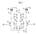
- FIG. 1 shows two ignition circuits of a multi-circuit ignition system, these ignition circuits each consisting of an ignition coil 10, 11 in FIG whose primary circuit is connected as a breaker in each case in a known manner, a power transistor 12, 13.
- the ignition coils 10, 11 are connected via terminals 14, 15 to the collectors of the power transistors 12, 13, whose emitters are grounded.
- the circuit area described so far relates to a known multi-circuit ignition system, wherein further ignition coils and power transistors can be connected in parallel accordingly.
- the series connection of the emitter-collector path of a pnp transistor 16 is connected to a voltage divider consisting of two resistors 17, 18.
- the series connection of a pnp transistor 19 with a voltage divider, which consists of a resistor 20 and the resistor 18, is connected in parallel with the switching path of the power transistor 13.
- the common tap of the two voltage dividers that is to say the connection of the resistor 18 facing away from ground, forms a summation point which is connected to a summation terminal 21.
- a capacitor 22 for suppressing voltages caused by the transient process during the ignition phase is connected in parallel with the resistor 18.
- a voltage terminal 23 connected to the positive pole of the supply voltage is connected to the base of the transistors 16, 19 via the series connection of a protective diode 24, 25 with a resistor 26, 27.
- the protection diodes 24, 25 serve as base protection diodes for the two transistors 16, 19.
- Control terminals 28, 29 each connected to the base of the two power transistors 12, 13 are connected to an electronic ignition control device in a manner which is not shown but is known.
- the transistors 16, 19 query the spark voltage on the primary side at the ignition coils 10, 11 connected thereto.
- the transistors 16, 19 deliver a collector current to the summation terminal 21 only when the voltage at the terminals 14 or 15 exceeds the value of the supply voltage, that is to say the voltage value at the terminal 23. This is the case during the ignition and burning process.
- the collector currents of the transistors 16 and 19 generate a defined level at the tap of the voltage dividers 17, 18 and 20, 18, that is to say at the summation terminal 21, which corresponds to the ignition and operating voltage.
- the second exemplary embodiment shown in FIG. 2 largely corresponds to the first exemplary embodiment.
- the same or equivalent components are provided with the same reference numerals and are not described again.
- a Zener diode 30 is now connected in parallel with the capacitor 22 as a protective circuit for protecting the transistors 16, 19 against impermissible inverse voltage.
- the resistor 18 connected between the summation terminal 21 and ground is still connected in the same way, but is now located in an evaluation circuit 32 which is connected to the summation terminal 21.
- the terminal 21 is via an analog / digital converter (A / D converter) 33 with an input of a microcomputer 34 connected. Furthermore, the terminal 21 is also connected to an input of the A / D converter 33 via an integrator 35.
- Control outputs of the microcomputer 34 control a control lamp 36 and six control switches 37 which interrupt the respective control signals for the corresponding injection valves (not shown) in order to interrupt the fuel supply to the six cylinders of an Otto engine.
- the number of control switches 37 is of course only exemplary, since in principle any number of injection valves for multi-cylinder internal combustion engines can be controlled.
- the microcomputer 37 can act on the integrator 35 via a line 38.
- the microcomputer 34 can be connected in a conventional manner via a data bus 39 to further components, assemblies or peripheral devices.
- a signal corresponding to the ignition and combustion voltage is generated at the summation terminal 21, the contour, level and duration of which depend on the respective combustion process or ignition process.
- an ideal combustion process has a specific signal curve that is stored in the microcomputer 34.
- the spark combustion signals which occur in succession at the summation terminal 21 are then recorded sequentially and in a time-controlled manner and compared with the ideal signal.
- a tolerance band can be defined which characterizes a still sufficient ignition process, with an excess indicating a missing or bad ignition process. If one is recognized, the control computer 36 is switched on by the microcomputer 34 and the fuel supply to the relevant cylinder is switched off. This can of course also be done in stages, that is, when a first tolerance limit is exceeded, the indicator light 36 is switched on and only after a Another criterion, for example a further tolerance level, is the fuel cut-off.
- the signal sequences at the summation terminal 21 can also be evaluated in a simpler manner, for example by only the levels or only the signal lengths can be checked. Such a simpler check can make the use of a microcomputer unnecessary.
- the voltage signals can be integrated at the summation terminal 21 by the integrator, as a result of which the combustion energy can be detected. This can also be used alternatively or as an additional criterion for the detection of good combustion. In principle, only the value of the result needs to be compared with a standardized value, but of course the integral course can also be checked.
- the integrator 35 can of course also be a component of the microcomputer 34 or be implemented as a function therein.
Description
Die Erfindung betrifft eine Vorrichtung zur Erkennung fehlender oder schlechter Verbrennung in Otto-Motoren mit Mehrkreis-Zündanlagen.The invention relates to a device for detecting missing or bad combustion in Otto engines with multi-circuit ignition systems.
Fehlende oder schlechte Verbrennungen in Otto-Motoren führen dazu, daß unverbranntes oder unvollständig verbranntes Gemisch in die Atmosphäre und insbesondere in den Katalysator gelangen kann. Neben einer Umweltbelastung führt dies unter Umständen zur Zerstörung des Katalysators. Vor allem bei Otto-Motoren mit vielen Zylindern, z. B. 6- bis 12-Zylinder-Motoren, merkt der Fahrer eines damit ausgerüsteten Kraftfahrzeuges den Ausfall eines Zylinders kaum. Auch bei Ausfall der Zündung oder unvollständige Verbrennung in mehreren Zylindern spürt er allenfalls einen gewissen Leistungsabfall, welcher aber auch andere Ursachen haben könnte. Es besteht daher die Gefahr, daß bei Auftreten von fehlenden oder schlechten Verbrennungen ein Motor weiter betrieben wird, was dann zur Zerstörung des Katalysators führt.Missing or bad burns in Otto engines lead to the fact that unburned or incompletely burned mixture can get into the atmosphere and in particular into the catalytic converter. In addition to environmental pollution, this can also destroy the catalytic converter. Especially with Otto engines with many cylinders, e.g. B. 6- to 12-cylinder engines, the driver of a motor vehicle equipped with it hardly notices the failure of a cylinder. Even if the ignition fails or the combustion incomplete in several cylinders, he may feel a certain drop in performance, which could also have other causes. There is therefore a risk that an engine will continue to be operated if missing or bad burns occur, which then leads to the destruction of the catalytic converter.
Aus der GB-A-2 172 115 ist bereits eine Vorrichtung zur Erfassung von Zündspannungsspitzen in den einzelnen Zylindern einer Mehrzylinder-Brennkraftmaschine beschrieben. Hierbei ist parallel zu einem Schalter im Primärkreis der Zündspule eine Diode vorgesehen, welche ein Signal durchschaltet, wenn die Spannung in der Primärwicklung einer Zündspule über der Versorgungsspannung liegt. Damit kann erkannt werden, in welchen Zylindern ein Zündsignal aufgetreten ist.From GB-A-2 172 115 a device for detecting ignition voltage peaks in the individual cylinders of a multi-cylinder internal combustion engine has already been described. In this case, a diode is provided in parallel with a switch in the primary circuit of the ignition coil, which switches a signal when the voltage in the primary winding of an ignition coil is above the supply voltage. It can be used to identify which Cylinders an ignition signal has occurred.
Die prinzipielle Auswertung einer Verbrennung mittels einer Fehlererkennungseinrichtung ist bereits aus der JP-A-63 295 840 bekannt.The basic evaluation of a combustion by means of an error detection device is already known from JP-A-63 295 840.
Die erfindungsgemäße Vorrichtung mit den Merkmalen des Hauptanspruchs hat den Vorteil, daß insbesondere auch bei Otto-Motoren mit Mehrkreis-Zündanlagen durch eine relativ einfache Schaltungsanordnung fehlende oder schlechte Verbrennungen erkannt und dann angezeigt oder zu entsprechenden Steuersignaien verarbeitet werden können. Dabei erhöht sich der Aufwand bei einem Otto-Motor mit sehr vielen Zylindern nur unerheblich gegenüber einem Otto-Motor mit einer geringen Zahl von Zylindern. Durch die Zusammenführung aller Funkenbrennsignale in einem Summationspunkt wird die Zahl der Signalverarbeitungskanäle auf einen reduziert. Es entsteht dann und nur dann ein derartiges Signal, wenn in dem betreffenden Zylinder eine Zündung stattgefunden hat. Die Zusammenführung der verschiedenen Funkenbrennsignale in einem Summationspunkt ist daher ohne Rücksicht auf überlappende Schließwinkel auch bei vielen Zündkreisen des Zündsystems möglich. Dieses Funkenbrennsignal kann daher ohne weiteren Aufwand in einem Analog/Digital-Kanal weiterverarbeitet werden. Der Pegel dieses Signals am Summationspunkt kann bezüglich seiner Amplitude und Dauer massebezogen bewertet werden.The device according to the invention with the features of the main claim has the advantage that missing or bad burns can be detected and then displayed or processed into corresponding control signals, especially in Otto engines with multi-circuit ignition systems, by means of a relatively simple circuit arrangement. The effort involved in an Otto engine with a large number of cylinders increases only insignificantly compared to an Otto engine with a small number of cylinders. The combination of all spark combustion signals in one summation point reduces the number of signal processing channels to one. Such a signal arises only when an ignition has taken place in the cylinder in question. The combination of the various spark combustion signals in a summation point is therefore possible regardless of overlapping closing angles even with many ignition circuits of the ignition system. This spark combustion signal can therefore be further processed in an analog / digital channel without further effort. The level and amplitude of this signal at the summation point can be evaluated in terms of mass.
Indem die Transistoren über Widerstände mit dem Summationspunkt verbunden sind und dieser über einen weiteren Widerstand an Masse liegt, bildet dieser weitere Widerstand mit jeweils einem der anderen Widerstände einen Spannungsteiler, dessen Abgriff immer an derselben Stelle liegt.Because the transistors are connected to the summation point via resistors and this is connected to ground via a further resistor, this further resistor forms a voltage divider with one of the other resistors, the tap of which is always at the same point.
Dies führt zu einer relativ einfachen Art der Zusammenführung der einzelnen Funkenbrennsignale.This leads to a relatively simple way of combining the individual spark combustion signals.
Durch die in den Unteransprüchen aufgeführten Maßnahmen sind vorteilhafte Weiterbildungen und Verbesserungen der im Hauptanspruch angegebenen Vorrichtung möglich.Advantageous further developments and improvements of the device specified in the main claim are possible through the measures listed in the subclaims.
Durch einen dem weiteren Widerstand parallelgeschalteten Kondensator kann der Einschwingvorgang während der Entflammungsphase unterdrückt werden, so daß einfacher auswertbare Signale entstehen.The transient process can be suppressed during the ignition phase by a capacitor connected in parallel with the further resistor, so that signals which are easier to evaluate are produced.
Eine besonders einfache Schaltungsanordnung zur Erfassung der Funkenbrennspannung besteht darin, daß die Transistoren als pnp-Transistoren ausgebildet sind, deren Emitter mit den jeweiligen Zündspulen, deren Basen mit dem positiven Versorgungsspannungspol und dessen Kollektoren mit dem Summationspunkt verbunden sind.A particularly simple circuit arrangement for detecting the spark voltage is that the transistors are designed as pnp transistors, the emitters of which are connected to the respective ignition coils, the bases of which are connected to the positive supply voltage pole and the collectors of which are connected to the summation point.
Eine vorteilhafte, mit dem Summationspunkt verbundene Auswerteeinrichtung vergleicht den Spannungsverlauf an diesem Summationspunkt mit einem einer guten Verbrennung entsprechenden Spannungsverlauf, wobei durch diese Auswerteeinrichtung bei einer vorbestimmten Abweichung eine Kontrolleinrichtung und/oder eine Abschalteinrichtung für die Kraftstoffzuführung des eine fehlende oder schlechte Verbrennung aufweisenden Zylinders des Otto-Motors aktivierbar ist. Im einfachsten Falle ist dabei die Kontrolleinrichtung als Kontrolleuchte ausgebildet, die den Fahrer eines entsprechenden Kraftfahrzeugs auf die fehlerhafte Zündung hinweist. Durch die Abschalteinrichtung wird zweckmäßigerweise eine Vorrichtung zur Sperrung eines zugeordneten Einspritzventils aktiviert, so daß kein weiterer Kraftstoff zufließen und daher auch kein unverbranntes Gemisch mehr in den Katalysator gelangen kann.An advantageous evaluation device connected to the summation point compares the voltage curve at this summation point with a voltage curve corresponding to a good combustion, with this evaluation device, in the event of a predetermined deviation, a control device and / or a switch-off device for the fuel supply of the Otto cylinder having missing or bad combustion -Motor can be activated. In the simplest case, the control device is designed as a control lamp which indicates to the driver of a corresponding motor vehicle that the ignition is faulty. The shutdown device expediently activates a device for blocking an associated injection valve, so that no further fuel flows in and therefore no unburned mixture can get into the catalytic converter.
Zur Erfassung der den jeweiligen Zylindern zugeordneten Funkenbrennsignale weist die Auswerteeinrichtung zweckmäßigerweise eine synchron zu den Zündvorgängen gesteuerte Abtastvorrichtung für den Summationspunkt auf. Die Auswertevorrichtung ist dabei in vorteilhafter Weise als Mikrorechner mit einem vorgeschalteten A/D-Wandler ausgebildet und kann auch beispielsweise in eine elektronische Motorsteuerung für Zündung und Einspritzung integriert sein.To detect the spark combustion signals assigned to the respective cylinders, the evaluation device expediently has a control that is controlled synchronously with the ignition processes Scanning device for the summation point. The evaluation device is advantageously designed as a microcomputer with an upstream A / D converter and can also be integrated, for example, in an electronic engine control for ignition and injection.
Durch Zwischenschalten eines Integrators, der die Funkenbrennspannung über die Brenndauer integriert, kann bei Berücksichtigung eines Korrekturfaktors für den Batteriespannungsteil ein Signal erhalten werden, das der Brennenergie entspricht. Auch der Integrator kann selbstverständlich im Mikrorechner realisiert sein.By interposing an integrator, which integrates the spark voltage over the burning time, a signal can be obtained that takes into account a correction factor for the battery voltage part, which corresponds to the burning energy. The integrator can of course also be implemented in the microcomputer.
Der weitere, mit Masse verbundene Widerstand kann auch der Auswerteeinrichtung räumlich zugeordnet sein, so daß sein Wert noch nachträglich ausschließlich durch Eingriff in die Auswerteeinrichtung verändert werden kann, wenn beispielsweise ein anderer Spannungspegel für ein anderes Auswertegerät erforderlich ist, oder wenn mehrere Zündendstufenmodule bei Systemen mit ruhender Zündverteilung nach dem Baukastenprinzip parallel geschaltet werden.The additional resistor connected to ground can also be spatially assigned to the evaluation device, so that its value can only be changed subsequently by intervening in the evaluation device if, for example, a different voltage level is required for another evaluation device, or if several ignition output modules in systems with static ignition distribution can be connected in parallel according to the modular principle.
Ausführungsbeispiele der Erfindung sind in der Zeichnung dargestellt und in der nachfolgenden Beschreibung näher erläutert. Es zeigen:
- Fig. 1
- ein Schaltbild eines ersten Ausführungsbeispiels und
- Fig. 2
- ein Schaltbild eines zweiten Ausführungsbeispiels mit einer daran angeschlossenen Auswerteschaltung.
- Fig. 1
- a circuit diagram of a first embodiment and
- Fig. 2
- a circuit diagram of a second embodiment with an evaluation circuit connected to it.
Das in Fig. 1 dargestellte Ausführungsbeispiel zeigt zwei Zündkreise einer Mehrkreis-Zündanlage, wobei diese Zündkreise jeweils aus einer Zündspule 10, 11 bestehen, in deren Primärkreis als Unterbrecher jeweils in bekannter Weise ein Leistungstransistor 12, 13 geschaltet ist. Die Zündspulen 10, 11 sind dabei über Klemmen 14, 15 mit den Kollektoren der Leistungstransistoren 12, 13 verbunden, deren Emitter an Masse liegen. Der bisher beschriebene Schaltungsbereich betrifft eine bekannte Mehrkreis-Zündanlage, wobei noch weitere Zündspulen und Leistungstransistoren entsprechend parallelgeschaltet sein können.The exemplary embodiment shown in FIG. 1 shows two ignition circuits of a multi-circuit ignition system, these ignition circuits each consisting of an
Parallel zur Schaltstrecke des Leistungstransistors 12 ist die Reihenschaltung der Emitter-Kollektor-Strecke eines pnp-Transistors 16 mit einem aus zwei Widerständen 17, 18 bestehenden Spannungsteiler geschaltet. Entsprechend ist parallel zu Schaltstrecke des Leistungstransistors 13 die Reihenschaltung eines pnp-Transistors 19 mit einem Spannungsteiler geschaltet, der aus einem Widerstand 20 und dem Widerstand 18 besteht. Der gemeinsame Abgriff beider Spannungsteiler, also der von Masse abgewandte Anschluß des Widerstands 18, bildet einen Summationspunkt, der mit einer Summationsklemme 21 verbunden ist. Parallel zum Widerstand 18 ist ein Kondensator 22 zur Unterdrückung von durch den Einschwingvorgang bedingten Spannungen während der Entflammungsphase geschaltet.Parallel to the switching path of the
Eine mit dem positiven Pol der Versorgungsspannung verbundene Spannungsklemme 23 ist jeweils über die Reihenschaltung einer Schutzdiode 24, 25 mit einem Widerstand 26, 27 an die Basis der Transistoren 16, 19 angeschlossen. Die Schutzdioden 24, 25 dienen dabei als Basisschutzdioden für die beiden Transistoren 16, 19.A
Jeweils mit der Basis der beiden Leistungstransistoren 12, 13 verbundene Steuerklemmen 28, 29 sind in nicht dargestellter, jedoch bekannter Weise mit einem elektronischen Zündsteuergerät verbunden.
Zur Erzeugung von Überwachungssignalen für die Zündvorgänge an der Summationsklemme 21 wird jeweils durch die Transistoren 16, 19 die primärseitige Funkenbrennspannung an den damit verbundenen Zündspulen 10, 11 abgefragt. Die Transistoren 16, 19 liefern einen Kollektorstrom zur Summationsklemme 21 nur dann, wenn die Spannung an den Klemmen 14 bzw. 15 den Wert der Versorgungsspannung, also den Spannungswert an der Klemme 23, überschreitet. Dies ist während des Zünd- und Brennvorgangs der Fall. Die Kollektorströme der Transistoren 16 bzw. 19 erzeugen am Abgriff der Spannungsteiler 17, 18 bzw. 20, 18, also an der Summationsklemme 21, einen definierten Pegel, der der Zünd- und Brennspannung entspricht. Wegen der sequentiellen Zündfolge der beiden Zündkreise oder weiterer Zündkreise des Zündsystems können alle Signale an der Summationsklemme 21 zusammengefaßt und danach zeitlich dem entsprechenden Zylinder zugeordnet werden. Dies erfolgt in einer Auswerteschaltung, wie sie in Fig. 2 näher dargestellt und erläutert wird.To generate monitoring signals for the ignition processes at the
Das in Fig. 2 dargestellte zweite Ausführungsbeispiel entspricht weitgehend dem ersten Ausführungsbeispiel . Gleiche oder gleich wirkende Bauteile sind mit denselben Bezugszeichen versehen und nicht nochmals beschrieben. Zusätzlich zum ersten Ausführungsbeispiel ist nunmehr eine Z-Diode 30 als Schutzbeschaltung zum Schutz der Transistoren 16, 19 gegen unzulässige Inversspannung dem Kondensator 22 parallelgeschaltet. Weiterhin ist der zwischen die Summationsklemme 21 und Masse geschaltete Widerstand 18 zwar immer noch in derselben Weise angeschlossen, er befindet sich jedoch nunmehr in einer Auswerteschaltung 32, die an die Summationsklemme 21 angeschlossen ist.The second exemplary embodiment shown in FIG. 2 largely corresponds to the first exemplary embodiment. The same or equivalent components are provided with the same reference numerals and are not described again. In addition to the first exemplary embodiment, a Zener
In der Auswerteschaltung 32 ist die Klemme 21 über einen Analog/Digial-Wandler (A/D-Wandler) 33 mit einem Eingang eines Mikrorechners 34 verbunden. Weiterhin ist die Klemme 21 über einen Integrator 35 ebenfalls mit einem Eingang des A/D-Wandlers 33 verbunden. Steuerausgänge des Mikrorechners 34 steuern eine Kontrolleuchte 36 sowie sechs Steuerschalter 37, die zur Unterbrechung der Kraftstoffzufuhr zu den sechs Zylindern eines Otto-Motors die jeweiligen Steuersignale für die entsprechenden, nicht dargestellten Einspritzventile unterbrechen. Die Zahl der Steuerschalter 37 ist selbstverständlich nur beispielhaft, da prinzipiell jede beliebige Zahl von Einspritzventilen für mehrzylindrige Brennkraftmaschinen gesteuert werden kann.In the
Über eine Leitung 38 kann der Mikrorechner 37 auf den Integrator 35 einwirken. Der Mikrorechner 34 ist in üblicher Weise über einen Datenbus 39 mit weiteren Bauelementen, Baugruppen oder Peripheriegeräten verbindbar.The
In Abhängigkeit des jeweils auftretenden Verbrennungsvorgangs wird an der Summationsklemme 21 ein der Zünd- und Brennspannung entsprechendes Signal erzeugt, dessen Kontur, Pegel und Dauer von dem jeweiligen Verbrennungsvorgang bzw. Zündvorgang abhängt. Ein idealer Verbrennungsvorgang weist dabei einen bestimmten Signalverlauf auf, der im Mikrorechner 34 gespeichert ist. Nun werden sequentiell und von den einzelnen Zündvorgängen zeitlich gesteuert die an der Summationsklemme 21 nacheinander auftretenden Funkenbrennsignale erfaßt und mit dem idealen Signal verglichen. Dabei kann, abhängig von der Batteriespannung, der Motordrehzahl und der Motorlast, ein Toleranzband definiert werden, das einen noch ausreichenden Zündvorgang kennzeichnet, wobei eine Überschreitung einen fehlenden oder schlechten Zündvorgang erkennen läßt. Wird ein solcher erkannt, so erfolgt durch den Mikrorechner 34 die Einschaltung der Kontrolleuchte 36 sowie eine Abschaltung der Brennstoffzufuhr zu dem betreffenden Zylinder. Dies kann selbstverständlich auch stufenweise erfolgen, das heißt, bei Überschreitung einer ersten Toleranzgrenze wird die Kontrollleuchte 36 eingeschaltet und erst nach Überschreitung eines weiteren Kriteriums, z.B. eines weiteren Toleranzpegels, erfolgt die Kraftstoffabschaltung.Depending on the combustion process occurring in each case, a signal corresponding to the ignition and combustion voltage is generated at the
Je nachdem, wie exakt die jeweiligen Vorgänge bestimmt und erkannt werden sollen, kann die Auswertung der Signalfolgen an der Summationsklemme 21 auch auf einfachere Weise erfolgen, indem z.B. nur die Pegel oder nur die Signallängen überprüft werden. Eine derartige einfachere Überprüfung kann die Verwendung eines Mikrorechners entbehrlich machen.Depending on how exactly the respective processes are to be determined and recognized, the signal sequences at the
Durch den Integrator können die Spannungssignale an der Summationsklemme 21 integriert werden, wodurch die Brennenergie erfaßt werden kann. Diese kann auch alternativ oder als zusätzliches Kriterium für die Erkennung einer guten Verbrennung herangezogen werden. Hierbei braucht prinzipiell nur der Wert des Ergebnisses mit einem genormten Wert verglichen werden, jedoch kann selbstverständlich auch der integrale Verlauf überprüft werden. Der Integrator 35 kann selbstverständlich auch Bestandteil des Mikrorechners 34 sein, bzw. als Funktion in diesem realisiert sein.The voltage signals can be integrated at the
Es ist auch weiterhin möglich, die Prüffunktionen des Mikrorechners 34 in einen Zentralrechner für den Otto-Motor zu verlegen, der diese Überwachungs- und Prüfungszonen mitübernimmt. Da gleichzeitig in diesem Zentralrechner die Zündsignale vorliegen, erleichtert dies den Soft- und Hardware-Aufwand.It is also possible to move the test functions of the
Claims (12)
- Device for detecting absent or poor combustion in Otto engines with multi-circuit ignition systems, each ignition circuit being assigned a transistor (16, 19) which can be controlled by the primary-side sparking voltage at the respective ignition coil (10, 11) and is connected via a resistor (17, 20) to a summing point (21) to which signals dependent on the control state of the transistors (16, 19) are applied, and the summing point (21) being connected to earth via a further resistor (18).
- Device according to Claim 1, characterized in that a capacitor (22) is connected in parallel with the further resistor (18).
- Device according to either of Claims 1 and 2, characterized in that the transistors (16, 19) are designed as pnp transistors, the emitters of which are connected to the respective ignition coil (10, 11), the bases of which are connected to the positive supply voltage terminal (23) and the collectors of which are connected to the summing point (21).
- Device according to Claim 3, characterized in that the base of the transistor (16, 19) is in each case connected to the positive supply voltage terminal (23) by the series connection of a resistor (26, 27) with a protective diode (24, 25).
- Device according to Claim 3 or 4, characterized in that the collector-emitter path of the transistors (16, 19) is protected from inverse voltages by a protection device (30).
- Device according to one of the preceding claims, characterized in that the summing point (21) is connected to an evaluation device (32) for comparison of the voltage profile with a voltage profile corresponding to good combustion, and in that, given a predetermined deviation, this evaluation device (32) can be used to activate an indicator device (36) and/or cut-off device (37) for the fuel supply to the cylinder of the Otto engine exhibiting absent or poor combustion.
- Device according to Claim 6, characterized in that the indicator device (36) is designed as an indicator lamp.
- Device according to Claim 6 or 7, characterized in that the cut-off device (37) has a device for inhibiting an associated injection signal for an injection valve.
- Device according to one of Claims 6 to 8, characterized in that the evaluation device (32) has a sampling device for the summing point (21), said sampling device being controlled in synchronism with the ignition processes.
- Device according to one of Claims 6 to 9, characterized in that the evaluation device (32) has a microcomputer with an A/D converter (33) arranged on its input side.
- Device according to one of Claims 6 to 10, characterized in that an integrating element (35) is arranged on the output side of the summing point (21) in the evaluation device.
- Device according to one of the preceding claims, characterized in that the further resistor (18) connected to earth is arranged in the evaluation device.
Applications Claiming Priority (2)
| Application Number | Priority Date | Filing Date | Title |
|---|---|---|---|
| DE3924130 | 1989-07-20 | ||
| DE3924130A DE3924130A1 (en) | 1989-07-20 | 1989-07-20 | DEVICE FOR DETECTING MISSING OR BAD BURNS IN OTTO ENGINES |
Publications (3)
| Publication Number | Publication Date |
|---|---|
| EP0408916A2 EP0408916A2 (en) | 1991-01-23 |
| EP0408916A3 EP0408916A3 (en) | 1992-02-19 |
| EP0408916B1 true EP0408916B1 (en) | 1996-09-18 |
Family
ID=6385522
Family Applications (1)
| Application Number | Title | Priority Date | Filing Date |
|---|---|---|---|
| EP90111724A Expired - Lifetime EP0408916B1 (en) | 1989-07-20 | 1990-06-21 | Installation for detecting a misfire or incomplete combustion in a combustion engine |
Country Status (3)
| Country | Link |
|---|---|
| US (1) | US5045796A (en) |
| EP (1) | EP0408916B1 (en) |
| DE (2) | DE3924130A1 (en) |
Families Citing this family (13)
| Publication number | Priority date | Publication date | Assignee | Title |
|---|---|---|---|---|
| DE4020986C2 (en) * | 1990-07-02 | 1998-09-03 | Telefunken Microelectron | Electronic ignition system for an internal combustion engine |
| DE59007572D1 (en) * | 1990-08-06 | 1994-12-01 | Siemens Ag | Ignition device for internal combustion engines. |
| DE4039356C1 (en) * | 1990-12-10 | 1992-07-16 | Robert Bosch Gmbh, 7000 Stuttgart, De | |
| DE4040236A1 (en) * | 1990-12-15 | 1992-06-17 | Bosch Gmbh Robert | DEVICE FOR DETECTING SIGNALS |
| DE4129292C2 (en) * | 1991-09-03 | 1993-12-02 | Daimler Benz Ag | Ignition malfunction detection method |
| US5190013A (en) * | 1992-01-10 | 1993-03-02 | Siemens Automotive L.P. | Engine intake valve selective deactivation system and method |
| US5493496A (en) * | 1992-12-15 | 1996-02-20 | Ford Motor Company | Cylinder number identification on a distributorless ignition system engine lacking CID |
| US5392641A (en) * | 1993-03-08 | 1995-02-28 | Chrysler Corporation | Ionization misfire detection apparatus and method for an internal combustion engine |
| US5321978A (en) * | 1993-04-05 | 1994-06-21 | Ford Motor Company | Method and apparatus for detecting cylinder misfire in an internal combustion engine |
| GB9316236D0 (en) * | 1993-08-05 | 1993-09-22 | Bowery William M | Cat guard-catalytic converter protection |
| JP3194676B2 (en) * | 1994-11-08 | 2001-07-30 | 三菱電機株式会社 | Misfire detection device for internal combustion engine |
| DE19630305A1 (en) * | 1996-07-26 | 1998-01-29 | Bosch Gmbh Robert | Circuit arrangement for measuring the ignition coil primary voltage of an ignition system of an internal combustion engine |
| DE10133005B4 (en) * | 2001-07-06 | 2014-10-23 | Volkswagen Ag | Method and device for detecting the interruption of the voltage supply of an ignition coil |
Family Cites Families (10)
| Publication number | Priority date | Publication date | Assignee | Title |
|---|---|---|---|---|
| US2335780A (en) * | 1941-08-19 | 1943-11-30 | Mccoy Charles Wilson | Testing apparatus |
| DE2759155C2 (en) * | 1977-12-31 | 1986-04-03 | Robert Bosch Gmbh, 7000 Stuttgart | Circuit arrangement for detecting the spark duration in ignition devices for internal combustion engines |
| JPS5751960A (en) * | 1980-09-11 | 1982-03-27 | Nippon Soken Inc | Ignition system diagnostic apparatus for internal combustion engine |
| DE3430000A1 (en) * | 1984-08-16 | 1986-02-27 | Robert Bosch Gmbh, 7000 Stuttgart | DEVICE FOR EVALUATING KNOCKING SIGNALS |
| GB8505875D0 (en) * | 1985-03-07 | 1985-04-11 | Ti Crypton Ltd | Engine analysers |
| GB8505874D0 (en) * | 1985-03-07 | 1985-04-11 | Ti Crypton Ltd | Engine analysers |
| KR920000053B1 (en) * | 1987-05-26 | 1992-01-06 | 미쓰비시전기 주식회사 | Engine control device |
| JPS63295840A (en) * | 1987-05-26 | 1988-12-02 | Mitsubishi Electric Corp | Engine control device |
| EP0344349B1 (en) * | 1988-06-03 | 1994-12-07 | Robert Bosch Gmbh | Detecting misfiring in spark ignition engines |
| US4918389A (en) * | 1988-06-03 | 1990-04-17 | Robert Bosch Gmbh | Detecting misfiring in spark ignition engines |
-
1989
- 1989-07-20 DE DE3924130A patent/DE3924130A1/en not_active Ceased
-
1990
- 1990-06-21 DE DE59010505T patent/DE59010505D1/en not_active Expired - Fee Related
- 1990-06-21 EP EP90111724A patent/EP0408916B1/en not_active Expired - Lifetime
- 1990-06-29 US US07/547,056 patent/US5045796A/en not_active Expired - Lifetime
Also Published As
| Publication number | Publication date |
|---|---|
| EP0408916A2 (en) | 1991-01-23 |
| US5045796A (en) | 1991-09-03 |
| EP0408916A3 (en) | 1992-02-19 |
| DE59010505D1 (en) | 1996-10-24 |
| DE3924130A1 (en) | 1991-01-31 |
Similar Documents
| Publication | Publication Date | Title |
|---|---|---|
| EP0408916B1 (en) | Installation for detecting a misfire or incomplete combustion in a combustion engine | |
| DE4324863C2 (en) | Circuit arrangement for flame detection | |
| DE19647138C2 (en) | Combustion state detector device for an internal combustion engine | |
| DE4138823C2 (en) | Device for detecting an ion current | |
| DE4133015C2 (en) | Ignition system for multi-cylinder internal combustion engines | |
| DE2800912A1 (en) | DEVICE FOR DETECTING MISSING IGNITIONS IN COMBUSTION MACHINES EQUIPPED WITH AN ELECTRONIC FUEL INJECTION SYSTEM | |
| DE19733869A1 (en) | Device for determining the combustion state of an internal combustion engine | |
| DE4133049C2 (en) | Ignition device for internal combustion engines | |
| DE4239592A1 (en) | ||
| EP0739448B1 (en) | Process for monitoring the running of an internal combustion engine to detect misfiring | |
| EP1476648B1 (en) | Method and device for identifying a phase of a four-stroke spark ignition engine | |
| EP0157006B1 (en) | Ignition device for an internal-combustion engine comprising a plurality of plugs without a distributor | |
| DE19648951C2 (en) | Misfire detection device for an internal combustion engine | |
| DE4239803C2 (en) | Ionization current detector device for an internal combustion engine | |
| DE4020986C2 (en) | Electronic ignition system for an internal combustion engine | |
| DE2652541A1 (en) | ELECTRONIC IGNITION SYSTEM FOR COMBUSTION MACHINERY | |
| EP0615582B1 (en) | Ignition system for an internal combustion engine | |
| DE3735234C2 (en) | Ignition monitoring device for detecting misfires in an ignition system for an internal combustion engine for a motor vehicle | |
| EP0502549B1 (en) | Spark survey in spark ignition engine | |
| EP0635638B1 (en) | Circuit for flame detection | |
| DE2335562A1 (en) | CIRCUIT ARRANGEMENT FOR GENERATION OF A TRIGGER BLANKING VOLTAGE WHEN ANALYZING THE IGNITION VOLTAGE COURSE OF COMBUSTION ENGINES | |
| DE4305197A1 (en) | Ignition circuit with over-current protection e.g. for IC engine - has current-limiting circuit to separate transistor circuit for each coil monitored via common supply resistor and op. amp. control to limit current to set levels. | |
| EP0747595B1 (en) | Device and method for detection of ignition | |
| EP1003967A1 (en) | Measuring and diagnostic device for an ignition system of an internal combustion engine | |
| DE2430389C2 (en) | Device for increasing the ignition voltage in ignition devices for internal combustion engines |
Legal Events
| Date | Code | Title | Description |
|---|---|---|---|
| PUAI | Public reference made under article 153(3) epc to a published international application that has entered the european phase |
Free format text: ORIGINAL CODE: 0009012 |
|
| AK | Designated contracting states |
Kind code of ref document: A2 Designated state(s): DE FR IT SE |
|
| PUAL | Search report despatched |
Free format text: ORIGINAL CODE: 0009013 |
|
| AK | Designated contracting states |
Kind code of ref document: A3 Designated state(s): DE FR IT SE |
|
| RAP3 | Party data changed (applicant data changed or rights of an application transferred) |
Owner name: ROBERT BOSCH GMBH |
|
| 17P | Request for examination filed |
Effective date: 19920716 |
|
| 17Q | First examination report despatched |
Effective date: 19950606 |
|
| GRAG | Despatch of communication of intention to grant |
Free format text: ORIGINAL CODE: EPIDOS AGRA |
|
| GRAH | Despatch of communication of intention to grant a patent |
Free format text: ORIGINAL CODE: EPIDOS IGRA |
|
| GRAH | Despatch of communication of intention to grant a patent |
Free format text: ORIGINAL CODE: EPIDOS IGRA |
|
| GRAA | (expected) grant |
Free format text: ORIGINAL CODE: 0009210 |
|
| AK | Designated contracting states |
Kind code of ref document: B1 Designated state(s): DE FR IT SE |
|
| ET | Fr: translation filed | ||
| REF | Corresponds to: |
Ref document number: 59010505 Country of ref document: DE Date of ref document: 19961024 |
|
| ET | Fr: translation filed | ||
| ITF | It: translation for a ep patent filed |
Owner name: STUDIO JAUMANN |
|
| PLBE | No opposition filed within time limit |
Free format text: ORIGINAL CODE: 0009261 |
|
| STAA | Information on the status of an ep patent application or granted ep patent |
Free format text: STATUS: NO OPPOSITION FILED WITHIN TIME LIMIT |
|
| 26N | No opposition filed | ||
| PGFP | Annual fee paid to national office [announced via postgrant information from national office to epo] |
Ref country code: FR Payment date: 20020622 Year of fee payment: 13 |
|
| PGFP | Annual fee paid to national office [announced via postgrant information from national office to epo] |
Ref country code: SE Payment date: 20020626 Year of fee payment: 13 |
|
| PGFP | Annual fee paid to national office [announced via postgrant information from national office to epo] |
Ref country code: DE Payment date: 20020802 Year of fee payment: 13 |
|
| PG25 | Lapsed in a contracting state [announced via postgrant information from national office to epo] |
Ref country code: SE Free format text: LAPSE BECAUSE OF NON-PAYMENT OF DUE FEES Effective date: 20030622 |
|
| PG25 | Lapsed in a contracting state [announced via postgrant information from national office to epo] |
Ref country code: DE Free format text: LAPSE BECAUSE OF NON-PAYMENT OF DUE FEES Effective date: 20040101 |
|
| EUG | Se: european patent has lapsed | ||
| PG25 | Lapsed in a contracting state [announced via postgrant information from national office to epo] |
Ref country code: FR Free format text: LAPSE BECAUSE OF NON-PAYMENT OF DUE FEES Effective date: 20040227 |
|
| REG | Reference to a national code |
Ref country code: FR Ref legal event code: ST |
|
| PG25 | Lapsed in a contracting state [announced via postgrant information from national office to epo] |
Ref country code: IT Free format text: LAPSE BECAUSE OF NON-PAYMENT OF DUE FEES;WARNING: LAPSES OF ITALIAN PATENTS WITH EFFECTIVE DATE BEFORE 2007 MAY HAVE OCCURRED AT ANY TIME BEFORE 2007. THE CORRECT EFFECTIVE DATE MAY BE DIFFERENT FROM THE ONE RECORDED. Effective date: 20050621 |