EP0408536B1 - Valve flange retainment system - Google Patents
Valve flange retainment system Download PDFInfo
- Publication number
- EP0408536B1 EP0408536B1 EP90870107A EP90870107A EP0408536B1 EP 0408536 B1 EP0408536 B1 EP 0408536B1 EP 90870107 A EP90870107 A EP 90870107A EP 90870107 A EP90870107 A EP 90870107A EP 0408536 B1 EP0408536 B1 EP 0408536B1
- Authority
- EP
- European Patent Office
- Prior art keywords
- flange
- valve body
- pipeline
- bosses
- boss
- Prior art date
- Legal status (The legal status is an assumption and is not a legal conclusion. Google has not performed a legal analysis and makes no representation as to the accuracy of the status listed.)
- Expired - Lifetime
Links
Images

Classifications
-
- F—MECHANICAL ENGINEERING; LIGHTING; HEATING; WEAPONS; BLASTING
- F16—ENGINEERING ELEMENTS AND UNITS; GENERAL MEASURES FOR PRODUCING AND MAINTAINING EFFECTIVE FUNCTIONING OF MACHINES OR INSTALLATIONS; THERMAL INSULATION IN GENERAL
- F16L—PIPES; JOINTS OR FITTINGS FOR PIPES; SUPPORTS FOR PIPES, CABLES OR PROTECTIVE TUBING; MEANS FOR THERMAL INSULATION IN GENERAL
- F16L23/00—Flanged joints
- F16L23/02—Flanged joints the flanges being connected by members tensioned axially
- F16L23/024—Flanged joints the flanges being connected by members tensioned axially characterised by how the flanges are joined to, or form an extension of, the pipes
- F16L23/028—Flanged joints the flanges being connected by members tensioned axially characterised by how the flanges are joined to, or form an extension of, the pipes the flanges being held against a shoulder
- F16L23/0286—Flanged joints the flanges being connected by members tensioned axially characterised by how the flanges are joined to, or form an extension of, the pipes the flanges being held against a shoulder the shoulder not being formed from the pipe
Definitions
- This invention is generally concerned with pipeline devices that are flange mounted and specifically with such devices that have loosely secured flanges.
- flanges are utilized to secure valve bodies, pipes and the like in abutting relationship in pipeline systems.
- Flanges are generally categorized as integral or separable depending upon whether they are an integral part of the valve body or pipe assembly or are separate and loosely attached thereto.
- the invention is directed to separable flanges which are generally required to be laterally and rotationally movable with respect to the pipeline assembly or valve body for installation purposes.
- Such flanges may be secured to their value body by any number of well known means, including split retention rings that nest in suitable retention grooves.
- a difficult problem is that in installing heavy valves and other pipeline devices, there is a need for a number of people to guard against the parts slipping or rotating while the line bolting is being installed.
- Prior art flanges require three or more people to assure a degree of safety in working on such heavy pipeline equipment.
- Another consideration is the need to retain the capability of changing flange gaskets in the field which requires that the separable flange be laterally moved on the pipeline device or valve body. This need for lateral movement is a detriment during installation and the ability of the separable flange mechanism to laterally move also contributes to safety concerns.
- GB-A- 2 069 084 discloses a discrete flange element adapted to connect an end of a pipe to that of an adjoining section of piping. It includes an integral flange ring and a securing hub with adjustable gripping bolts for securing the flange ring to the surrounded pipe end preventing movement between the flange ring and the pipe end.
- FR-A-2 354 504 is relative to an assembling device for pipes by means of "V" shaped flange rings, wherein each flange ring surrounds the respective pipe end by means of a sleeve member, the interior surface of the sleeve member and the outer surface of the pipe end having a complementary annular surface profile.
- the sleeve member may comprise an inner groove with a radial pin at the assembling end of the pipes and the corresponding pipe end may be provided with a ring member rigidly fixed on it and interrupted by an axial slot for sliding engagement of said pin.
- the flange ring is first arranged on the pipe end; then the ring member is fixed to the pipe end and the flange ring is slided back towards the pipe end, guided by the pin sliding in said axial slot until the pin disengages the slot. A slight rotary movement of the flange ring fixes it in axial direction.
- a principal object of the invention is to provide an improved separable flange arrangement.
- Another object of the invention is to provide a valve body and separable flange arrangement of novel contruction.
- a further object of the invention is to provide a novel retainment system for securing a separable flange to a valve body or the like.
- the pipeline device comprises a body defining a circumferential groove ; a split ring positioned in said groove ; a loosely mounted annular flange secured to said body by engaging said split ring, and including an inner orifice sized to slip over the end of a pipe fitting ; said pipeline device further comprising a first mating boss on said valve body ; a second mating boss on one side of said flange, said bosses being juxtaposed each other in axial direction, in one orientation of said flange and said body ; a U-shaped retainer device, having a U-shaped cross-section throughout the extent thereof, straddling said first and second bosses and maintaining said flange and said body in said one orientation; and fastener means for securing said retainer device in position.
- Said fastener means may include a threaded aperture formed in said first boss; a hole formed in the bight portion of said U-shaped retainer device ; and a bolt passing through said hole and engaging said threaded aperture .
- a prior art valve assembly 10 includes a valve body 12, a pair of separable flanges 14 and 16, an actuator 18 and a positioner 20. A plurality of gauges 22 are also illustrated. Assembly 10 is well known in the prior art and as can be seen, is a relatively heavy massive structure that gives rise to some difficulty in installation since the separable flanges 14 and 16 are loosely retained on valve body 12.
- the separable flange shown in FIG. 2 is identical to that described and claimed in the above referenced U.S. patent with the exception of a generally rectangular boss 28 on one side.
- the flange 14 is annular and includes an inner orifice 23 that is sized to slip over the end of a pipe fitting or valve body.
- Flange 14 generally has an outwardly tapered cross section as indicated at 26, for strain equalization.
- An undercut portion 30 is provided in one side of flange 14 for engaging a split ring retainer to secure the flange on the pipeline fitting or valve body.
- Boss 28 may be either formed as part of flange 14 or added thereto by welding or the like.
- FIG. 4 the general configuration of the valve body 12 is shown.
- An integral mounting flange 32 for mounting the valve body to an actuator is shown and a valve chamber 34 is also indicated.
- a pair of retention grooves 36 and 36a are located at each end of valve body 12 for securing separable flanges thereto by means of split ring retention devices, (not shown).
- a pair of generally rectangular bosses 38 and 38a are formed on body 12 adjacent retention grooves 36 and 36a, respectively.
- the respective bosses 38 and 38a have threaded holes 40 and 40a formed therein. Bosses 38 and 38a may of course, be separate from valve body 12 and attached thereto by any suitable means of attachment such as welding, rather than being integrally formed, as shown.
- flange 14 is shown assembled to one end of body 12. Specifically, the action of split retention ring 46 in securing the flange to the body is shown. Split ring 46 nests in retention groove 36 and is maintained therein by flange 14. Undercut portion 30 precludes removal of flange 14 from body 12 by virtue of split retention ring 46 and retention groove 36.
- a generally U shaped retainer 42 of heavy construction is illustrated in FIG. 7 and shown in cross section in FIG. 6.
- Retainer 42 includes an aperture 48 in its bight portion for enabling it to be secured to boss 38 by means of a screw or bolt 44. Since the retainer 42 straddles the bosses 28 and 38, it not only prevents relative rotational movement between flange 14 and body 12 but it also prevents lateral movement of flange 14 with respect to body 12. This is due to the very limited clearance between the ends of the bosses 28 and 38 when the bosses are in alignment. Therefore, with a single fastener, flange 14 is locked in position on body 12. It will be appreciated that removal of bolt 44 and retainer 42 will permit rotation of flange 14 with respect to body 12.
- flange 14 By rotating flange 14 approximately 30 degrees, it can be moved laterally (to the right as viewed in FIG. 6) on body 12 to permit removal of the split retention ring 46, should that be required. During normal work on a pipeline, it is sometimes required to replace one or more flange gaskets. In that instance, the flange needs to be moved laterally to permit access to the gasket. As has been shown, this can be readily accomplished with the retainer system of the invention.
Landscapes
- Engineering & Computer Science (AREA)
- General Engineering & Computer Science (AREA)
- Mechanical Engineering (AREA)
- Valve Housings (AREA)
- Flanged Joints, Insulating Joints, And Other Joints (AREA)
Description
- This invention is generally concerned with pipeline devices that are flange mounted and specifically with such devices that have loosely secured flanges. As is well known, flanges are utilized to secure valve bodies, pipes and the like in abutting relationship in pipeline systems. Flanges are generally categorized as integral or separable depending upon whether they are an integral part of the valve body or pipe assembly or are separate and loosely attached thereto. The invention is directed to separable flanges which are generally required to be laterally and rotationally movable with respect to the pipeline assembly or valve body for installation purposes. Such flanges may be secured to their value body by any number of well known means, including split retention rings that nest in suitable retention grooves.
- In U.S. Patent No. 4,767,138, a novel hubless flange is described and claimed. That flange is secured to a pipeline device by means of a split ring and a retention groove in the device. The retainment system of the invention is described in connection with that flange and a suitable valve body, but it should be understood that other types of pipeline devices and flanges may also benefit from the invention.
- A difficult problem is that in installing heavy valves and other pipeline devices, there is a need for a number of people to guard against the parts slipping or rotating while the line bolting is being installed. Prior art flanges require three or more people to assure a degree of safety in working on such heavy pipeline equipment. Another consideration is the need to retain the capability of changing flange gaskets in the field which requires that the separable flange be laterally moved on the pipeline device or valve body. This need for lateral movement is a detriment during installation and the ability of the separable flange mechanism to laterally move also contributes to safety concerns.
- GB-A- 2 069 084 discloses a discrete flange element adapted to connect an end of a pipe to that of an adjoining section of piping. It includes an integral flange ring and a securing hub with adjustable gripping bolts for securing the flange ring to the surrounded pipe end preventing movement between the flange ring and the pipe end.
- FR-A-2 354 504 is relative to an assembling device for pipes by means of "V" shaped flange rings, wherein each flange ring surrounds the respective pipe end by means of a sleeve member, the interior surface of the sleeve member and the outer surface of the pipe end having a complementary annular surface profile. The sleeve member may comprise an inner groove with a radial pin at the assembling end of the pipes and the corresponding pipe end may be provided with a ring member rigidly fixed on it and interrupted by an axial slot for sliding engagement of said pin. The flange ring is first arranged on the pipe end; then the ring member is fixed to the pipe end and the flange ring is slided back towards the pipe end, guided by the pin sliding in said axial slot until the pin disengages the slot. A slight rotary movement of the flange ring fixes it in axial direction.
- With the retainment system of the invention, a simple low cost arrangement is provided for securing the separable flange from both lateral and rotational movement with respect to the body of the pipeline device.
- A principal object of the invention is to provide an improved separable flange arrangement.
- Another object of the invention is to provide a valve body and separable flange arrangement of novel contruction.
- A further object of the invention is to provide a novel retainment system for securing a separable flange to a valve body or the like.
- According to the invention, the pipeline device comprises a body defining a circumferential groove ;
a split ring positioned in said groove ;
a loosely mounted annular flange secured to said body by engaging said split ring, and including an inner orifice sized to slip over the end of a pipe fitting ;
said pipeline device further comprising
a first mating boss on said valve body ;
a second mating boss on one side of said flange, said bosses being juxtaposed each other in axial direction, in one orientation of said flange and said body ;
a U-shaped retainer device, having a U-shaped cross-section throughout the extent thereof, straddling said first and second bosses and maintaining said flange and said body in said one orientation; and
fastener means for securing said retainer device in position. - Said fastener means may include
a threaded aperture formed in said first boss;
a hole formed in the bight portion of said U-shaped retainer device ; and
a bolt passing through said hole and engaging said threaded aperture . - These and other objects and advantages of the invention will be apparent upon reading the following description in conjunction with the drawings in which:
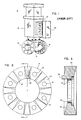
- FIG. 1 is a perspective view of a prior art combination actuator, positioner and valve body having separable flanges;
- FIG. 2 is a plan view of a separable flange constructed in accordance with the invention;
- FIG. 3 is a sectional view of the flange of FIG. 2 taken along the line 3-3;
- FIG. 4 is a plan view of a valve body constructed in accordance with the invention;
- FIG. 5 is a sectional view of the valve body of FIG. 4 taken along the line 5-5;
- FIG. 6 is a partial view showing the retainment system of the invention; and
- FIG. 7 is a perspective view of a retainer device constructed in accordance with the invention.
- In FIG. 1, a prior
art valve assembly 10 includes avalve body 12, a pair ofseparable flanges actuator 18 and apositioner 20. A plurality ofgauges 22 are also illustrated.Assembly 10 is well known in the prior art and as can be seen, is a relatively heavy massive structure that gives rise to some difficulty in installation since theseparable flanges valve body 12. - The separable flange shown in FIG. 2 is identical to that described and claimed in the above referenced U.S. patent with the exception of a generally
rectangular boss 28 on one side. Viewing FIG. 2 in conjunction with FIG. 3, theflange 14 is annular and includes aninner orifice 23 that is sized to slip over the end of a pipe fitting or valve body.Flange 14 generally has an outwardly tapered cross section as indicated at 26, for strain equalization. Anundercut portion 30 is provided in one side offlange 14 for engaging a split ring retainer to secure the flange on the pipeline fitting or valve body.Boss 28 may be either formed as part offlange 14 or added thereto by welding or the like. - In FIG. 4 the general configuration of the
valve body 12 is shown. Anintegral mounting flange 32 for mounting the valve body to an actuator is shown and avalve chamber 34 is also indicated. A pair ofretention grooves 36 and 36a are located at each end ofvalve body 12 for securing separable flanges thereto by means of split ring retention devices, (not shown). A pair of generallyrectangular bosses body 12adjacent retention grooves 36 and 36a, respectively. Therespective bosses holes Bosses valve body 12 and attached thereto by any suitable means of attachment such as welding, rather than being integrally formed, as shown. - In FIG. 6,
flange 14 is shown assembled to one end ofbody 12. Specifically, the action ofsplit retention ring 46 in securing the flange to the body is shown. Splitring 46 nests inretention groove 36 and is maintained therein byflange 14.Undercut portion 30 precludes removal offlange 14 frombody 12 by virtue ofsplit retention ring 46 andretention groove 36. - A generally U shaped
retainer 42 of heavy construction is illustrated in FIG. 7 and shown in cross section in FIG. 6.Retainer 42 includes anaperture 48 in its bight portion for enabling it to be secured toboss 38 by means of a screw orbolt 44. Since theretainer 42 straddles thebosses flange 14 andbody 12 but it also prevents lateral movement offlange 14 with respect tobody 12. This is due to the very limited clearance between the ends of thebosses flange 14 is locked in position onbody 12. It will be appreciated that removal ofbolt 44 andretainer 42 will permit rotation offlange 14 with respect tobody 12. By rotatingflange 14 approximately 30 degrees, it can be moved laterally (to the right as viewed in FIG. 6) onbody 12 to permit removal of thesplit retention ring 46, should that be required. During normal work on a pipeline, it is sometimes required to replace one or more flange gaskets. In that instance, the flange needs to be moved laterally to permit access to the gasket. As has been shown, this can be readily accomplished with the retainer system of the invention. - What has been described is a novel loose flange retainment system for precluding inadvertent movement of the flange on a valve body or pipeline device.
Claims (3)
- A pipeline device having a body (12) defining a circumferential groove (36);
a split ring (46) positioned in said groove (36);
a loosely mounted annular flange (14) secured to said body (12) by engaging said split ring (46), and including an inner orifice (23) sized to slip over the end of a pipe fitting ;
characterized in that it further comprises
a first mating boss (38) on said body (12);
a second mating boss (28) on one side of said flange (14), said bosses (28, 38) being juxtaposed each other in axial direction, in one orientation of said flange (14) and said body (12);
a U-shaped retainer device (42), having a U-shaped cross-section throughout the extent thereof, straddling said first (38) and second (28) bosses and maintaining said flange (14) and said body (12) in said one orientation; and
fastener means (44) for securing said retainer device (42) in position. - A device according to Claim 1, wherein said fastner means include
a threaded aperture (40) formed in said first boss;
a hole formed (48) in the bight portion of said U-shaped retainer device (42); and
a bolt (44) passing through said hole (48) and engaging said threaded aperture (40) - A device according to any of claims 1 or 2 wherein the pipeline device is a valve body.
Applications Claiming Priority (2)
| Application Number | Priority Date | Filing Date | Title |
|---|---|---|---|
| US07/378,405 US4991881A (en) | 1989-07-10 | 1989-07-10 | Valve flange retainment system |
| US378405 | 1989-07-10 |
Publications (2)
| Publication Number | Publication Date |
|---|---|
| EP0408536A1 EP0408536A1 (en) | 1991-01-16 |
| EP0408536B1 true EP0408536B1 (en) | 1993-06-09 |
Family
ID=23493010
Family Applications (1)
| Application Number | Title | Priority Date | Filing Date |
|---|---|---|---|
| EP90870107A Expired - Lifetime EP0408536B1 (en) | 1989-07-10 | 1990-07-09 | Valve flange retainment system |
Country Status (5)
| Country | Link |
|---|---|
| US (1) | US4991881A (en) |
| EP (1) | EP0408536B1 (en) |
| JP (1) | JPH0351598A (en) |
| CA (1) | CA2020770A1 (en) |
| DE (1) | DE69001870T2 (en) |
Families Citing this family (8)
| Publication number | Priority date | Publication date | Assignee | Title |
|---|---|---|---|---|
| EP0521145B1 (en) * | 1991-01-14 | 1996-12-18 | Precision Dynamics Corporation | Cannula guard |
| US8297664B2 (en) * | 2009-03-10 | 2012-10-30 | Xavier Pottier | Fastening flange |
| CH707656B1 (en) * | 2013-02-20 | 2018-01-31 | R Nussbaum Ag | Component with fluid-carrying pipe section and separate fluid-free flange. |
| US9228682B1 (en) * | 2013-03-15 | 2016-01-05 | John W. Rocheleau | Two-piece pipe flange and systems |
| CN104455840A (en) * | 2014-11-06 | 2015-03-25 | 苏州市诚键法兰制造有限公司 | Novel anti-skid stainless steel flange |
| CN104439937A (en) * | 2014-11-06 | 2015-03-25 | 苏州市诚键法兰制造有限公司 | Method for manufacturing anti-skid stainless steel flange |
| WO2021206938A1 (en) * | 2020-04-08 | 2021-10-14 | Parker-Hannifin Corporation | Flange-mounted inline valve with integrated electrical feed |
| US12449072B1 (en) * | 2024-07-10 | 2025-10-21 | Cosmoind Co., Ltd | Pipe connection device |
Family Cites Families (25)
| Publication number | Priority date | Publication date | Assignee | Title |
|---|---|---|---|---|
| BE351943A (en) * | ||||
| US1307160A (en) * | 1919-06-17 | a hptt cl | ||
| US1186021A (en) * | 1915-07-09 | 1916-06-06 | Leslie Company | Coupling. |
| US1186621A (en) * | 1915-11-04 | 1916-06-13 | Frank Townsend | Pipe-coupling. |
| GB206538A (en) * | 1922-05-08 | 1923-11-08 | Roe A V & Co Ltd | Improvements in or relating to socket and spigot joints for tubes and the like |
| US1914736A (en) * | 1930-05-21 | 1933-06-20 | Coutu Alfred Joachim | Angular ball swivel union |
| US1881508A (en) * | 1931-10-26 | 1932-10-11 | Standard Steel Works | Pipe coupling |
| GB563581A (en) * | 1943-04-14 | 1944-08-21 | George Spencer Moulton & Co | Improvements in and relating to pipe couplings |
| US2472307A (en) * | 1946-01-23 | 1949-06-07 | Nagel Henryk | Coupling device for detachably securing sunshades, filter holders, and like accessories to the lens barrels of cameras |
| US3091487A (en) * | 1960-04-14 | 1963-05-28 | William H Gallagher | Clip |
| US3026128A (en) * | 1960-04-21 | 1962-03-20 | Aeroquip Corp | Remote operational joint coupling |
| FR1293138A (en) * | 1961-03-30 | 1962-05-11 | Commissariat Energie Atomique | Improvements made to pipe fitting systems |
| US3418009A (en) * | 1966-11-22 | 1968-12-24 | Raphael T Pollia | Flanged pipe joint |
| AT277680B (en) * | 1967-04-25 | 1970-01-12 | Engelbert Heinz Hawle | Connector for connecting smooth pipes to one another or to fixed flanges of fittings, flange pipes or the like. |
| US3468572A (en) * | 1967-08-07 | 1969-09-23 | Walter D Haentjens | Shaft coupling |
| US3768843A (en) * | 1970-01-13 | 1973-10-30 | Laval Turbine | Tubing coupling |
| BE788082R (en) * | 1971-08-30 | 1972-12-18 | Victaulic Co Of America | COUPLINGS BETWEEN A TUBE AND A FLANGE AND METHODS FOR ESTABLISHING THESE |
| FI53274A7 (en) * | 1974-02-22 | 1975-08-23 | Goeran Sundholm | |
| FR2354504A1 (en) * | 1976-06-08 | 1978-01-06 | Pont A Mousson | Physically engaged collars for pipe couplings, with compression seals - for coupling pipe without welding |
| GB2069084B (en) * | 1980-02-11 | 1983-09-14 | Uni Flange Corp | Flanged element for pipe couplings |
| SU932078A1 (en) * | 1980-11-04 | 1982-05-30 | Научно-производственное объединение "ЭНЕРГИЯ" | Quick-release pipeline connection |
| US4660266A (en) * | 1981-11-14 | 1987-04-28 | Joachim Horn | Split-flange connector and method of making same |
| US4767138A (en) * | 1982-04-30 | 1988-08-30 | Fisher Controls International, Inc. | Hubless Flange |
| US4648630A (en) * | 1983-02-16 | 1987-03-10 | David A. Zornes | Fire hose coupling lock |
| US4779900A (en) * | 1987-02-11 | 1988-10-25 | Ebaa Iron Inc. | Segmented pipe joint retainer glands |
-
1989
- 1989-07-10 US US07/378,405 patent/US4991881A/en not_active Expired - Fee Related
-
1990
- 1990-07-04 JP JP2175439A patent/JPH0351598A/en active Pending
- 1990-07-09 EP EP90870107A patent/EP0408536B1/en not_active Expired - Lifetime
- 1990-07-09 CA CA002020770A patent/CA2020770A1/en not_active Abandoned
- 1990-07-09 DE DE90870107T patent/DE69001870T2/en not_active Expired - Fee Related
Also Published As
| Publication number | Publication date |
|---|---|
| DE69001870T2 (en) | 1993-11-18 |
| CA2020770A1 (en) | 1991-01-11 |
| JPH0351598A (en) | 1991-03-05 |
| DE69001870D1 (en) | 1993-07-15 |
| US4991881A (en) | 1991-02-12 |
| EP0408536A1 (en) | 1991-01-16 |
Similar Documents
| Publication | Publication Date | Title |
|---|---|---|
| US4966395A (en) | Rigid or flexible coupling for pipes | |
| US5609370A (en) | Positive latch quick connector | |
| US4275867A (en) | Valve assembly and method | |
| CA1143409A (en) | Coupling for coupling tubular elements | |
| US4694853A (en) | Wafer check valves | |
| CA1259778A (en) | Clip attachment | |
| EP0088508B1 (en) | Valve assembly | |
| US5558344A (en) | Exhaust pipe flange gasket | |
| EP0004428A1 (en) | Ball and valve with readily removable ball and seats for high temperature environment | |
| GB2107436A (en) | Fireproof butterfly valve | |
| EP3380766A1 (en) | Valve coupling having centering support projections | |
| US4991881A (en) | Valve flange retainment system | |
| US4436326A (en) | Flexible coupling for fluid ducts | |
| US5546976A (en) | Condensate trap installations | |
| US4674529A (en) | Check valve | |
| GB2257468A (en) | Driveline yoke seal fastener | |
| US5340169A (en) | Locking device for laid pipes with embedded insert | |
| US5209496A (en) | Universal seal or packing gland | |
| US4575048A (en) | Insert retainer for a wafer style butterfly valve | |
| US7390265B2 (en) | Flexible coupling device | |
| EP4139599B1 (en) | Pipe coupling sleeve assembly | |
| CN113167308A (en) | Pneumatic valve/pressure vessel plastic metal composite lid with bayonet retention feature | |
| CA1208191A (en) | Bidirectional valve seal | |
| US10927973B2 (en) | Pneumatic valve/pressure vessel subcomponent with bayonet retention feature | |
| US6116809A (en) | Rotating assembly with internal retaining ring |
Legal Events
| Date | Code | Title | Description |
|---|---|---|---|
| PUAI | Public reference made under article 153(3) epc to a published international application that has entered the european phase |
Free format text: ORIGINAL CODE: 0009012 |
|
| AK | Designated contracting states |
Kind code of ref document: A1 Designated state(s): DE FR GB IT NL |
|
| 17P | Request for examination filed |
Effective date: 19910606 |
|
| 17Q | First examination report despatched |
Effective date: 19911217 |
|
| GRAA | (expected) grant |
Free format text: ORIGINAL CODE: 0009210 |
|
| AK | Designated contracting states |
Kind code of ref document: B1 Designated state(s): DE FR GB IT NL |
|
| REF | Corresponds to: |
Ref document number: 69001870 Country of ref document: DE Date of ref document: 19930715 |
|
| ITF | It: translation for a ep patent filed | ||
| ET | Fr: translation filed | ||
| PLBE | No opposition filed within time limit |
Free format text: ORIGINAL CODE: 0009261 |
|
| STAA | Information on the status of an ep patent application or granted ep patent |
Free format text: STATUS: NO OPPOSITION FILED WITHIN TIME LIMIT |
|
| 26N | No opposition filed | ||
| PGFP | Annual fee paid to national office [announced via postgrant information from national office to epo] |
Ref country code: GB Payment date: 19940629 Year of fee payment: 5 |
|
| PGFP | Annual fee paid to national office [announced via postgrant information from national office to epo] |
Ref country code: DE Payment date: 19940708 Year of fee payment: 5 |
|
| PGFP | Annual fee paid to national office [announced via postgrant information from national office to epo] |
Ref country code: FR Payment date: 19940711 Year of fee payment: 5 |
|
| PGFP | Annual fee paid to national office [announced via postgrant information from national office to epo] |
Ref country code: NL Payment date: 19940731 Year of fee payment: 5 |
|
| PG25 | Lapsed in a contracting state [announced via postgrant information from national office to epo] |
Ref country code: GB Effective date: 19950709 |
|
| PG25 | Lapsed in a contracting state [announced via postgrant information from national office to epo] |
Ref country code: NL Effective date: 19960201 |
|
| GBPC | Gb: european patent ceased through non-payment of renewal fee |
Effective date: 19950709 |
|
| NLV4 | Nl: lapsed or anulled due to non-payment of the annual fee |
Effective date: 19960201 |
|
| PG25 | Lapsed in a contracting state [announced via postgrant information from national office to epo] |
Ref country code: DE Effective date: 19960402 |
|
| PG25 | Lapsed in a contracting state [announced via postgrant information from national office to epo] |
Ref country code: FR Effective date: 19960430 |
|
| REG | Reference to a national code |
Ref country code: FR Ref legal event code: ST |
|
| REG | Reference to a national code |
Ref country code: FR Ref legal event code: ST |
|
| REG | Reference to a national code |
Ref country code: FR Ref legal event code: ST |
|
| PG25 | Lapsed in a contracting state [announced via postgrant information from national office to epo] |
Ref country code: IT Free format text: LAPSE BECAUSE OF NON-PAYMENT OF DUE FEES;WARNING: LAPSES OF ITALIAN PATENTS WITH EFFECTIVE DATE BEFORE 2007 MAY HAVE OCCURRED AT ANY TIME BEFORE 2007. THE CORRECT EFFECTIVE DATE MAY BE DIFFERENT FROM THE ONE RECORDED. Effective date: 20050709 |