EP0408531A1 - Verfahren zur Herstellung eines geteilten kreisförmigen Ringes - Google Patents
Verfahren zur Herstellung eines geteilten kreisförmigen Ringes Download PDFInfo
- Publication number
- EP0408531A1 EP0408531A1 EP90850211A EP90850211A EP0408531A1 EP 0408531 A1 EP0408531 A1 EP 0408531A1 EP 90850211 A EP90850211 A EP 90850211A EP 90850211 A EP90850211 A EP 90850211A EP 0408531 A1 EP0408531 A1 EP 0408531A1
- Authority
- EP
- European Patent Office
- Prior art keywords
- ring
- partitions
- casing
- hot pressing
- partition
- Prior art date
- Legal status (The legal status is an assumption and is not a legal conclusion. Google has not performed a legal analysis and makes no representation as to the accuracy of the status listed.)
- Granted
Links
Images

Classifications
-
- B—PERFORMING OPERATIONS; TRANSPORTING
- B22—CASTING; POWDER METALLURGY
- B22F—WORKING METALLIC POWDER; MANUFACTURE OF ARTICLES FROM METALLIC POWDER; MAKING METALLIC POWDER; APPARATUS OR DEVICES SPECIALLY ADAPTED FOR METALLIC POWDER
- B22F5/00—Manufacture of workpieces or articles from metallic powder characterised by the special shape of the product
- B22F5/04—Manufacture of workpieces or articles from metallic powder characterised by the special shape of the product of turbine blades
-
- F—MECHANICAL ENGINEERING; LIGHTING; HEATING; WEAPONS; BLASTING
- F01—MACHINES OR ENGINES IN GENERAL; ENGINE PLANTS IN GENERAL; STEAM ENGINES
- F01D—NON-POSITIVE DISPLACEMENT MACHINES OR ENGINES, e.g. STEAM TURBINES
- F01D5/00—Blades; Blade-carrying members; Heating, heat-insulating, cooling or antivibration means on the blades or the members
- F01D5/12—Blades
- F01D5/28—Selecting particular materials; Particular measures relating thereto; Measures against erosion or corrosion
-
- F—MECHANICAL ENGINEERING; LIGHTING; HEATING; WEAPONS; BLASTING
- F05—INDEXING SCHEMES RELATING TO ENGINES OR PUMPS IN VARIOUS SUBCLASSES OF CLASSES F01-F04
- F05D—INDEXING SCHEME FOR ASPECTS RELATING TO NON-POSITIVE-DISPLACEMENT MACHINES OR ENGINES, GAS-TURBINES OR JET-PROPULSION PLANTS
- F05D2250/00—Geometry
- F05D2250/10—Two-dimensional
- F05D2250/14—Two-dimensional elliptical
- F05D2250/141—Two-dimensional elliptical circular
Definitions
- the invention relates to a method in manufacturing a split circular ring, preferably a vane ring or sealing ring of a turbine.
- the vane rings of turbines are fixedly mounted in the turbine housing and enclose the turbine shaft in an annular groove therein, a sealing ring (shaft seal or labyrinth seal) being provided to a seal between the vane ring and the bottom of the annular groove.
- a sealing ring shaft seal or labyrinth seal
- the vane ring is made in two parts, i.e. it is split along a diametrical plane while the sealing ring is made in four parts, i.e. it is split in two mutually perpendicular diametrical planes.
- the four parts of the sealing ring are pressed against the bottom of the annular groove in the turbine shaft by helical springs which are received in radial bottom holes in the sealing ring and abut the vane ring.
- the rings are split by making radial cuts therethrough, which as far as the vane ring is concerned hardly can be effected without at least one cut passes through one of the vanes, which means that the vane has to be repared, and this is a big job.
- a great number of working operations are required which make the manufacture considerably more expensive.
- the purpose of the invention is to simplify the manufacture of primarily vane rings and sealings rings of turbines by reducing the number of working operations, and for this purpose the invention provides a method of the kind referred to above, which has obtained according to the invention the features appearing from claim 1.
- FIG. 1 there are diagrammatically indicated a turbine housing 10 and a turbine shaft 11, said shaft carrying a blade ring 12.
- Stationary vane rings 13 fixedly mounted to the turbine housing are provided one at each side of the blade ring 12, said vane rings being received in grooves 14 in the turbine shaft and sealing against the bottom thereof by means of sealing rings 15.
- a substantially greater number of blade and vane rings are of course provided in a turbine; the only purpose of the diagrammatic figure shown herein is to illustrate the principal arrangement of the rings.
- the vane rings 13 and the sealing rings 15 must be split in order to be mounted around the turbine shaft 11.
- said ring is produced by isostatic hot pressing.
- the isostatic hot pressing is performed in a casing having an inner cylindrical wall 16 and an outer cylindrical wall 17 and two annular plane endwalls, an upper wall 18 and a lower wall 19, the upper wall being provided with a pipe connection 20 for evacuation of the casing.
- partitions are mounted in a diametrical plane of the casing, which is indicated by a dot and dash line 24.
- These partitions should have the same cross sectional shape as the casing and should consist of the same kind of sheet as the casing. They form a V-shaped ridge 26, which extends radially across the sheet.
- the partitions have an aperture 27 to allow passage of the core therethrough. In the present case the core is located adjacent the upper end wall 18, and the aperture for the core then can be formed as a recess in the upper edge of the partition.
- the core is to be located centrally in the casing it is necessary to split the partition, the two parts thereof being interconnected at the rear side of the partition by means of a joint sheet which is bolted to the two portions of the partition.
- the partition should have at one side thereof a coating of release agent, e.g. an alumina layer having a thickness 10 ⁇ m.
- the casing In the manufacture of the vane ring the casing is filled with a metal powder 28 which should be the same metal alloy as that the casing and the partitions are made of, the powder penetrating into the apertures 23 to form the vanes of the vane ring.
- a metal powder 28 which should be the same metal alloy as that the casing and the partitions are made of, the powder penetrating into the apertures 23 to form the vanes of the vane ring.
- the two halves of the vane ring will be separated from each other at the partitions 25 because said halves have a coating of release agent at one side thereof, one interface having a ridge 26 and the other interface having a corresponding groove, so that an accurate matching of the two halves of the vane ring will be facilitated.
- the two parts can be interconnected by means of bolt connections or by welding.
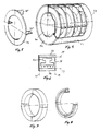
- a casing for isostatic hot pressing comprises an inner cylindrical wall 30, an outer cylindrical wall 31 and two annular end walls 32 and 33. Connection for evacuation should of course be provided but is not shown herein.
- Inside the casing a number of annular circular partitions 34 are provided said partitions having four flanges 35 projecting axially from one side of the partition, said flanges having rectangular shape and being slightly spaced inwardly of the outer and inner circular edges of the partition.
- the flanges are located in two mutually perpendicular diametrical planes of the partition and are coated with release agent at one side thereof.
- the partition is also coated with release agent.
- the partitions are located in the casing mutually spaced a distance which is slightly greater than the distance over which the flanges project from the partition, so that the flanges are slightly spaced from the side of the adjacent partition, which is coated with release agent, and it should also be noted that the partitions have an outer diameter which is shlightly smaller than the inside diameter of the outer cylindrical wall 30.
- a monolithic body has been obtained in which the partitions are embedded.
- This body can be split into individual rings by being turned at the outside and the inside thereof to the broken lines 36 and 37, which correspond to the inner and outer circular edges of the annular partition 34. Release will take place at the line 38 corresponding to the interface against the surface coated with release agent of the adjacent partition.
- the ring obtained is in one piece according to FIG. 7.
- the ring In order that the ring will devide into four equal parts defined by the flanges 35 which form partitions between the parts, the ring must be turned to a profile which is located inwardly of the dot and dash lines 39 in FIG. 6, said profile being defined by the shape of the flanges 35.
- the ring is turned initially at the outside and the sides thereof and finally at the inside so that the ring during this last turning which causes the ring to be divided into four parts, can be kept together in a chuck.
- FIG. 6 the desired profile of the sealing ring is shown at 40.
- the finished ring is shown in FIG. 8 where one of the parts is removed.
Landscapes
- Engineering & Computer Science (AREA)
- Mechanical Engineering (AREA)
- Chemical & Material Sciences (AREA)
- Materials Engineering (AREA)
- General Engineering & Computer Science (AREA)
- Manufacturing & Machinery (AREA)
- Powder Metallurgy (AREA)
- Diaphragms For Electromechanical Transducers (AREA)
Priority Applications (1)
| Application Number | Priority Date | Filing Date | Title |
|---|---|---|---|
| AT90850211T ATE97043T1 (de) | 1989-06-01 | 1990-05-25 | Verfahren zur herstellung eines geteilten kreisfoermigen ringes. |
Applications Claiming Priority (2)
| Application Number | Priority Date | Filing Date | Title |
|---|---|---|---|
| SE8901983 | 1989-06-01 | ||
| SE8901983A SE463702B (sv) | 1989-06-01 | 1989-06-01 | Saett vid framstaellning av en delad cirkulaer ring |
Publications (2)
| Publication Number | Publication Date |
|---|---|
| EP0408531A1 true EP0408531A1 (de) | 1991-01-16 |
| EP0408531B1 EP0408531B1 (de) | 1993-11-10 |
Family
ID=20376145
Family Applications (1)
| Application Number | Title | Priority Date | Filing Date |
|---|---|---|---|
| EP90850211A Expired - Lifetime EP0408531B1 (de) | 1989-06-01 | 1990-05-25 | Verfahren zur Herstellung eines geteilten kreisförmigen Ringes |
Country Status (6)
| Country | Link |
|---|---|
| US (1) | US5082623A (de) |
| EP (1) | EP0408531B1 (de) |
| JP (1) | JP2846927B2 (de) |
| AT (1) | ATE97043T1 (de) |
| DE (1) | DE69004506T2 (de) |
| SE (1) | SE463702B (de) |
Cited By (5)
| Publication number | Priority date | Publication date | Assignee | Title |
|---|---|---|---|---|
| DE4319727A1 (de) * | 1993-06-15 | 1994-12-22 | Mtu Muenchen Gmbh | Verfahren zur Herstellung eines Schaufelringes für trommelartige Rotoren von Turbomaschinen |
| DE19607159A1 (de) * | 1996-02-26 | 1997-08-28 | Abb Patent Gmbh | Leitboden für eine Turbine mit Leitprofilen, die an einem Außenring befestigt sind |
| WO1999002289A1 (en) * | 1997-07-08 | 1999-01-21 | Sandvik Ab (Publ) | Method for manufacturing inserts with holes for clamping |
| WO2014204534A1 (en) * | 2013-03-15 | 2014-12-24 | Rolls-Royce North American Technologies, Inc. | Titanium-aluminide components |
| CN105828986A (zh) * | 2013-12-20 | 2016-08-03 | 山特维克知识产权股份有限公司 | 用于制造包层部件的方法 |
Families Citing this family (6)
| Publication number | Priority date | Publication date | Assignee | Title |
|---|---|---|---|---|
| SE462899B (sv) * | 1988-12-21 | 1990-09-17 | Abb Stal Ab | Saett att tillverka med skovelkrans foersedda ringar eller skivor |
| US6218026B1 (en) * | 1995-06-07 | 2001-04-17 | Allison Engine Company | Lightweight high stiffness member and manufacturing method thereof |
| US5724643A (en) * | 1995-06-07 | 1998-03-03 | Allison Engine Company, Inc. | Lightweight high stiffness shaft and manufacturing method thereof |
| US6202277B1 (en) | 1999-10-28 | 2001-03-20 | General Electric Company | Reusable hard tooling for article consolidation and consolidation method |
| US20060245923A1 (en) * | 2005-04-27 | 2006-11-02 | General Electric Company | Arcuate nozzle segment and related method of manufacture |
| CN106660125B (zh) * | 2014-05-30 | 2023-03-17 | 诺沃皮尼奥内技术股份有限公司 | 制造涡轮机构件的方法、涡轮机构件和涡轮机 |
Citations (6)
| Publication number | Priority date | Publication date | Assignee | Title |
|---|---|---|---|---|
| US4097276A (en) * | 1975-07-17 | 1978-06-27 | The Garrett Corporation | Low cost, high temperature turbine wheel and method of making the same |
| EP0002918A1 (de) * | 1977-12-23 | 1979-07-11 | Ford Motor Company Limited | Verfahren zum Behandeln eines keramischen Formkörpers vor dem Heisspressen und der so behandelte keramische Formkörper; Verfahren zum Herstellen eines keramischen Verbundkörpers und so erhaltener Verbundkörper |
| EP0072424A1 (de) * | 1981-08-14 | 1983-02-23 | Mtu Motoren- Und Turbinen-Union MàNchen Gmbh | Verfahren zum Herstellen von Sinterteilen grosser Genauigkeit |
| EP0073651A1 (de) * | 1981-08-27 | 1983-03-09 | ASEA Stal Aktiebolag | Verfahren zur Herstellung von Schaufelelementen für rotierende Strömungsmaschinen |
| EP0086417A2 (de) * | 1982-02-13 | 1983-08-24 | Mtu Motoren- Und Turbinen-Union MàNchen Gmbh | Kapsel für das heissisostatische Pressen von hochbeanspruchten und kompliziert geformten Werkstücken für Turbomaschinen |
| WO1987005241A1 (en) * | 1986-03-04 | 1987-09-11 | Asea Stal Ab | Method for manufacturing metallic products from powder by hot isostatic pressing using ceramic cores |
Family Cites Families (4)
| Publication number | Priority date | Publication date | Assignee | Title |
|---|---|---|---|---|
| US4526748A (en) * | 1980-05-22 | 1985-07-02 | Kelsey-Hayes Company | Hot consolidation of powder metal-floating shaping inserts |
| US4526747A (en) * | 1982-03-18 | 1985-07-02 | Williams International Corporation | Process for fabricating parts such as gas turbine compressors |
| US4587700A (en) * | 1984-06-08 | 1986-05-13 | The Garrett Corporation | Method for manufacturing a dual alloy cooled turbine wheel |
| US4680160A (en) * | 1985-12-11 | 1987-07-14 | Trw Inc. | Method of forming a rotor |
-
1989
- 1989-06-01 SE SE8901983A patent/SE463702B/sv not_active IP Right Cessation
-
1990
- 1990-05-25 AT AT90850211T patent/ATE97043T1/de not_active IP Right Cessation
- 1990-05-25 EP EP90850211A patent/EP0408531B1/de not_active Expired - Lifetime
- 1990-05-25 DE DE90850211T patent/DE69004506T2/de not_active Expired - Fee Related
- 1990-05-31 US US07/531,236 patent/US5082623A/en not_active Expired - Fee Related
- 1990-06-01 JP JP2141760A patent/JP2846927B2/ja not_active Expired - Fee Related
Patent Citations (6)
| Publication number | Priority date | Publication date | Assignee | Title |
|---|---|---|---|---|
| US4097276A (en) * | 1975-07-17 | 1978-06-27 | The Garrett Corporation | Low cost, high temperature turbine wheel and method of making the same |
| EP0002918A1 (de) * | 1977-12-23 | 1979-07-11 | Ford Motor Company Limited | Verfahren zum Behandeln eines keramischen Formkörpers vor dem Heisspressen und der so behandelte keramische Formkörper; Verfahren zum Herstellen eines keramischen Verbundkörpers und so erhaltener Verbundkörper |
| EP0072424A1 (de) * | 1981-08-14 | 1983-02-23 | Mtu Motoren- Und Turbinen-Union MàNchen Gmbh | Verfahren zum Herstellen von Sinterteilen grosser Genauigkeit |
| EP0073651A1 (de) * | 1981-08-27 | 1983-03-09 | ASEA Stal Aktiebolag | Verfahren zur Herstellung von Schaufelelementen für rotierende Strömungsmaschinen |
| EP0086417A2 (de) * | 1982-02-13 | 1983-08-24 | Mtu Motoren- Und Turbinen-Union MàNchen Gmbh | Kapsel für das heissisostatische Pressen von hochbeanspruchten und kompliziert geformten Werkstücken für Turbomaschinen |
| WO1987005241A1 (en) * | 1986-03-04 | 1987-09-11 | Asea Stal Ab | Method for manufacturing metallic products from powder by hot isostatic pressing using ceramic cores |
Cited By (6)
| Publication number | Priority date | Publication date | Assignee | Title |
|---|---|---|---|---|
| DE4319727A1 (de) * | 1993-06-15 | 1994-12-22 | Mtu Muenchen Gmbh | Verfahren zur Herstellung eines Schaufelringes für trommelartige Rotoren von Turbomaschinen |
| DE19607159A1 (de) * | 1996-02-26 | 1997-08-28 | Abb Patent Gmbh | Leitboden für eine Turbine mit Leitprofilen, die an einem Außenring befestigt sind |
| WO1999002289A1 (en) * | 1997-07-08 | 1999-01-21 | Sandvik Ab (Publ) | Method for manufacturing inserts with holes for clamping |
| US6287352B1 (en) | 1997-07-08 | 2001-09-11 | Smith International, Inc. | Method for manufacturing inserts with holes for clamping |
| WO2014204534A1 (en) * | 2013-03-15 | 2014-12-24 | Rolls-Royce North American Technologies, Inc. | Titanium-aluminide components |
| CN105828986A (zh) * | 2013-12-20 | 2016-08-03 | 山特维克知识产权股份有限公司 | 用于制造包层部件的方法 |
Also Published As
| Publication number | Publication date |
|---|---|
| SE8901983L (sv) | 1990-12-02 |
| DE69004506T2 (de) | 1994-03-03 |
| JPH03111501A (ja) | 1991-05-13 |
| DE69004506D1 (de) | 1993-12-16 |
| ATE97043T1 (de) | 1993-11-15 |
| US5082623A (en) | 1992-01-21 |
| JP2846927B2 (ja) | 1999-01-13 |
| EP0408531B1 (de) | 1993-11-10 |
| SE8901983D0 (sv) | 1989-06-01 |
| SE463702B (sv) | 1991-01-14 |
Similar Documents
| Publication | Publication Date | Title |
|---|---|---|
| EP0408531A1 (de) | Verfahren zur Herstellung eines geteilten kreisförmigen Ringes | |
| EP2971667B1 (de) | Bauteil für ein gasturbinentriebwerk und verfahren zur herstellung eines bauteils für ein gasturbinentriebwerk | |
| EP2841703B1 (de) | Geometrien für gasturbinenmotorschaufeln und kerne für herstellungsverfahren | |
| US6482533B2 (en) | Article having imbedded cavity | |
| GB2274418A (en) | Unitary rotors having hollow blades and their manufacture | |
| RU2353480C2 (ru) | Способ изготовления цельных облопаченных роторов | |
| US4575327A (en) | Enclosure for the hot-isostatic pressing of highly stressed workpieces of complex shape for turbomachines | |
| US4208777A (en) | Method for manufacturing a split engine casing from a cylinder | |
| US4483054A (en) | Method for making a drum rotor | |
| GB2181374A (en) | Support fixture for turbine blades | |
| GB2086772A (en) | Method of fabricating a hollow article | |
| US5536145A (en) | Method of manufacturing a turbine wheel having inserted blades, and a wheel obtained by performing the method | |
| US4855103A (en) | Method for manufacturing metallic products from powder by hot isostatic pressing using ceramic cores | |
| CN116323089B (zh) | 用于生产进气唇缘的环形扇区的制造 | |
| US4743126A (en) | Hydrodynamic bearings, and secondary assemblies for producing said bearings | |
| EP0436996B1 (de) | Kolbenringe | |
| EP0989316B1 (de) | Drehmomenttragendes element in einem kraftfahrzeuggetriebe, verfahren zur herstellung von zännen und vorrichtung zum formen derselben | |
| US5772401A (en) | Diaphragm construction for turbomachinery | |
| US6916550B2 (en) | Method of manufacturing a metal matrix composite structure | |
| EP0857537A1 (de) | Schneideeinsatz für Schleifwerkzeug | |
| EP0449932B1 (de) | Verfahren zur herstellung von ringen oder scheiben mit einem blatt- oder flügelrand | |
| EP1651370B1 (de) | Verfahren zur herstellung eines geteilten gehäuses | |
| EP1222981B1 (de) | Verfahren zur Herstellung eines Brennkraftmaschinengehäuses | |
| US20240227004A1 (en) | Method for manufacturing a fan disk with a part by additive manufacturing | |
| SU1140860A1 (ru) | Способ изготовлени крупногабаритных фланцев |
Legal Events
| Date | Code | Title | Description |
|---|---|---|---|
| PUAI | Public reference made under article 153(3) epc to a published international application that has entered the european phase |
Free format text: ORIGINAL CODE: 0009012 |
|
| AK | Designated contracting states |
Kind code of ref document: A1 Designated state(s): AT BE CH DE FR GB IT LI |
|
| 17P | Request for examination filed |
Effective date: 19910412 |
|
| 17Q | First examination report despatched |
Effective date: 19930324 |
|
| GRAA | (expected) grant |
Free format text: ORIGINAL CODE: 0009210 |
|
| AK | Designated contracting states |
Kind code of ref document: B1 Designated state(s): AT BE CH DE FR GB IT LI |
|
| REF | Corresponds to: |
Ref document number: 97043 Country of ref document: AT Date of ref document: 19931115 Kind code of ref document: T |
|
| ITF | It: translation for a ep patent filed | ||
| REF | Corresponds to: |
Ref document number: 69004506 Country of ref document: DE Date of ref document: 19931216 |
|
| ET | Fr: translation filed | ||
| PLBE | No opposition filed within time limit |
Free format text: ORIGINAL CODE: 0009261 |
|
| STAA | Information on the status of an ep patent application or granted ep patent |
Free format text: STATUS: NO OPPOSITION FILED WITHIN TIME LIMIT |
|
| 26N | No opposition filed | ||
| PGFP | Annual fee paid to national office [announced via postgrant information from national office to epo] |
Ref country code: BE Payment date: 20000505 Year of fee payment: 11 |
|
| PGFP | Annual fee paid to national office [announced via postgrant information from national office to epo] |
Ref country code: CH Payment date: 20000526 Year of fee payment: 11 |
|
| PG25 | Lapsed in a contracting state [announced via postgrant information from national office to epo] |
Ref country code: BE Free format text: LAPSE BECAUSE OF NON-PAYMENT OF DUE FEES Effective date: 20010531 |
|
| PG25 | Lapsed in a contracting state [announced via postgrant information from national office to epo] |
Ref country code: LI Free format text: LAPSE BECAUSE OF NON-PAYMENT OF DUE FEES Effective date: 20010624 Ref country code: CH Free format text: LAPSE BECAUSE OF NON-PAYMENT OF DUE FEES Effective date: 20010624 |
|
| BERE | Be: lapsed |
Owner name: ABB STAL A.B. Effective date: 20010531 |
|
| REG | Reference to a national code |
Ref country code: GB Ref legal event code: IF02 |
|
| REG | Reference to a national code |
Ref country code: CH Ref legal event code: PL |
|
| PGFP | Annual fee paid to national office [announced via postgrant information from national office to epo] |
Ref country code: GB Payment date: 20030512 Year of fee payment: 14 |
|
| PGFP | Annual fee paid to national office [announced via postgrant information from national office to epo] |
Ref country code: AT Payment date: 20030519 Year of fee payment: 14 |
|
| PGFP | Annual fee paid to national office [announced via postgrant information from national office to epo] |
Ref country code: FR Payment date: 20030530 Year of fee payment: 14 |
|
| PGFP | Annual fee paid to national office [announced via postgrant information from national office to epo] |
Ref country code: DE Payment date: 20030630 Year of fee payment: 14 |
|
| PG25 | Lapsed in a contracting state [announced via postgrant information from national office to epo] |
Ref country code: GB Free format text: LAPSE BECAUSE OF NON-PAYMENT OF DUE FEES Effective date: 20040525 Ref country code: AT Free format text: LAPSE BECAUSE OF NON-PAYMENT OF DUE FEES Effective date: 20040525 |
|
| PG25 | Lapsed in a contracting state [announced via postgrant information from national office to epo] |
Ref country code: DE Free format text: LAPSE BECAUSE OF NON-PAYMENT OF DUE FEES Effective date: 20041201 |
|
| GBPC | Gb: european patent ceased through non-payment of renewal fee |
Effective date: 20040525 |
|
| PG25 | Lapsed in a contracting state [announced via postgrant information from national office to epo] |
Ref country code: FR Free format text: LAPSE BECAUSE OF NON-PAYMENT OF DUE FEES Effective date: 20050131 |
|
| REG | Reference to a national code |
Ref country code: FR Ref legal event code: ST |
|
| PG25 | Lapsed in a contracting state [announced via postgrant information from national office to epo] |
Ref country code: IT Free format text: LAPSE BECAUSE OF NON-PAYMENT OF DUE FEES;WARNING: LAPSES OF ITALIAN PATENTS WITH EFFECTIVE DATE BEFORE 2007 MAY HAVE OCCURRED AT ANY TIME BEFORE 2007. THE CORRECT EFFECTIVE DATE MAY BE DIFFERENT FROM THE ONE RECORDED. Effective date: 20050525 |