EP0408518A1 - Verfahren und System zur Überwachung des Betriebsverhaltens einer Mehrzylinder-Brennkraftmaschine, insbesondere einer Brennkraftmaschine mit elektronischer Einspritzung - Google Patents
Verfahren und System zur Überwachung des Betriebsverhaltens einer Mehrzylinder-Brennkraftmaschine, insbesondere einer Brennkraftmaschine mit elektronischer Einspritzung Download PDFInfo
- Publication number
- EP0408518A1 EP0408518A1 EP90830264A EP90830264A EP0408518A1 EP 0408518 A1 EP0408518 A1 EP 0408518A1 EP 90830264 A EP90830264 A EP 90830264A EP 90830264 A EP90830264 A EP 90830264A EP 0408518 A1 EP0408518 A1 EP 0408518A1
- Authority
- EP
- European Patent Office
- Prior art keywords
- engine
- cylinder
- combustion
- lack
- fuel
- Prior art date
- Legal status (The legal status is an assumption and is not a legal conclusion. Google has not performed a legal analysis and makes no representation as to the accuracy of the status listed.)
- Granted
Links
- 238000002485 combustion reaction Methods 0.000 title claims abstract description 40
- 238000000034 method Methods 0.000 title claims abstract description 9
- 238000012544 monitoring process Methods 0.000 title claims description 17
- 238000002347 injection Methods 0.000 title abstract description 13
- 239000007924 injection Substances 0.000 title abstract description 13
- 239000000446 fuel Substances 0.000 claims abstract description 14
- 239000000203 mixture Substances 0.000 claims abstract description 14
- 238000007789 sealing Methods 0.000 claims abstract description 8
- 230000003313 weakening effect Effects 0.000 claims abstract description 7
- 230000001133 acceleration Effects 0.000 claims description 8
- 238000001514 detection method Methods 0.000 claims description 5
- 230000000750 progressive effect Effects 0.000 claims description 3
- 230000003213 activating effect Effects 0.000 claims 1
- 230000007257 malfunction Effects 0.000 abstract description 4
- 230000006835 compression Effects 0.000 abstract description 3
- 238000007906 compression Methods 0.000 abstract description 3
- 238000005259 measurement Methods 0.000 abstract description 3
- 238000012360 testing method Methods 0.000 description 5
- 238000012545 processing Methods 0.000 description 4
- 230000007935 neutral effect Effects 0.000 description 3
- 238000010276 construction Methods 0.000 description 2
- 238000013461 design Methods 0.000 description 2
- 238000010586 diagram Methods 0.000 description 2
- 230000000694 effects Effects 0.000 description 2
- 238000004519 manufacturing process Methods 0.000 description 2
- 239000000243 solution Substances 0.000 description 2
- 230000002411 adverse Effects 0.000 description 1
- 230000007547 defect Effects 0.000 description 1
- 230000000994 depressogenic effect Effects 0.000 description 1
- 238000011161 development Methods 0.000 description 1
- 230000018109 developmental process Effects 0.000 description 1
Images
Classifications
-
- G—PHYSICS
- G01—MEASURING; TESTING
- G01M—TESTING STATIC OR DYNAMIC BALANCE OF MACHINES OR STRUCTURES; TESTING OF STRUCTURES OR APPARATUS, NOT OTHERWISE PROVIDED FOR
- G01M15/00—Testing of engines
- G01M15/04—Testing internal-combustion engines
- G01M15/11—Testing internal-combustion engines by detecting misfire
-
- G—PHYSICS
- G01—MEASURING; TESTING
- G01M—TESTING STATIC OR DYNAMIC BALANCE OF MACHINES OR STRUCTURES; TESTING OF STRUCTURES OR APPARATUS, NOT OTHERWISE PROVIDED FOR
- G01M15/00—Testing of engines
- G01M15/04—Testing internal-combustion engines
- G01M15/042—Testing internal-combustion engines by monitoring a single specific parameter not covered by groups G01M15/06 - G01M15/12
- G01M15/046—Testing internal-combustion engines by monitoring a single specific parameter not covered by groups G01M15/06 - G01M15/12 by monitoring revolutions
-
- F—MECHANICAL ENGINEERING; LIGHTING; HEATING; WEAPONS; BLASTING
- F02—COMBUSTION ENGINES; HOT-GAS OR COMBUSTION-PRODUCT ENGINE PLANTS
- F02D—CONTROLLING COMBUSTION ENGINES
- F02D2200/00—Input parameters for engine control
- F02D2200/02—Input parameters for engine control the parameters being related to the engine
- F02D2200/10—Parameters related to the engine output, e.g. engine torque or engine speed
- F02D2200/1015—Engines misfires
Definitions
- the present invention relates generally to the monitoring of the operating characteristics of internal combustion engines with several cylinders, particularly internal combustion engines with electronic injection.
- a first object of the present invention is to provide this analysis function in a manner which is simple both from the point of view of the production of the electronic control unit (preferably with the use of a control unit in current production) and as regards the diagnostic equipment, without adversely affecting the accuracy of the diagnostic sequence.
- control unit can provide the said information relating to the analysis also enables the control unit to be adjusted automatically by means of feedback, possibly in real time, so that the operating parameters can be adjusted following developments in the operating conditions of the engine.
- a further object of the present invention is to provide means which can identify selectively conditions of malfunction which are attributable essentially to inadequate sealing of the pistons in the respective cylinders (an inadequate compression ratio).
- a system according to the invention operates during a checking stage in which the engine is in neutral (virtually inertial operating conditions, according to criteria which will better be described below) and the accelerator is fully depressed.
- the system acts on the fuel-injection function so as to make the engine accelerate and decelerate at full power between two preset rates of revolution (for example 1400 and 5800 revs/min). At each acceleration the metering of the fuel is varied so as to achieve a gradual weakening of the mixture.
- each cylinder begins to have an absence of combustion is detected (preferably by means of a dynamic measurement of the torque delivered by each cylinder).
- the detection of this lack of combustion, and the identification of the conditions under which it arises, enable the injection system to be analysed thoroughly, particularly as regards the fuel metering limits.
- This information can be obtained and used in the engine-design stage, in the calibration and adjustment stage (the tuning stage), and also for an automatic self-adjustment action carried out directly on the injection function under the normal conditions of use of the engine in a vehicle.
- a system according to the invention enables a lack of combustion which is not linked to the fuel metering to be identified clearly so that conditions of malfunction resulting from disturbances of various origin, for example the improper operation of the ignition system, can be identified.
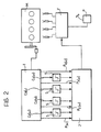
- the primary source of the signals for use by the processing functions in the currently preferred embodiment of the present invention is a module for the dynamic monitoring of the torque and of the power delivered by the individual cylinders of a motor-vehicle engine M (not illustrated as a whole), produced according to the solution described in Italian patent No. 1 180 045.
- This patent describes the construction of a device, herein generally indicated 1, which, by monitoring the angular acceleration and velocity of rotation of the engine M at particular points or regions - of its rotary travel, is able to provide respective signals C1( ⁇ ), C2( ⁇ ), C3( ⁇ ) and C4( ⁇ ), which are indicative of the torque (useful and/or braking) associated with each cylinder of the engine M.
- a device herein generally indicated 1
- the monitoring is carried out with the engine M being made to "cycle" through successive acceleration and deceleration phases.
- the system according to the invention includes a processing or governing module (2) for carrying out the desired testing or analysis function upon receipt of a command which is applied by the driver (or whoever is performing the test) by means of a push button 3.
- the receipt of this command causes a subsequent acceleration command, applied by the full depression of the corresponding pedal P (accelerator pedal pushed to the floor continuously with the engine in neutral), to be transferred to the central unit F which controls the fuel injection so as to result in a sequence of successive phases of acceleration and deceleration between two preset rates of rotation (e.g. 1400 and 5800 revs./min).
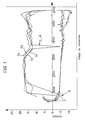
- any lack of combustion occurring in any one of the cylinders can be detected immediately from the respective graph of Figure 1 and is in the form of a rapid downward flicker A in the signal of the torque (or power) delivered: a cylinder in which there is no combustion does not in fact deliver any useful torque but, on the contrary, has a purely braking effect.
- a lack of combustion may occur only in correspondence with a particular range of values of the rate of rotation ⁇ of the engine.
- a signal corresponding to the graph of Figure 1 thus enables the range of values of the rate of rotation ⁇ at which lack of combustion occurs, to be identified precisely.
- the module 2 acts on the injection control unit F so as to send a generally rich mixture to all the cylinders.
- the detection of any lack of combustion in one or more of the cylinders can immediately be attributed to a defect in systems other than the injection system, for example, in the ignition system.
- the identification of such an anomaly can therefore be indicated externally immediately.
- the system according to the invention proceeds with successive cycles of dynamic monitoring of the useful torque and the braking torque delivered by the various cylinders of the engine M with a progressive and gradual weakening of the mixture sent to the various cylinders.
- the module 2 acquires the information relating to the conditions (the metering of the mixture, the rate of rotation of the engine, etc.) in which the lack of combustion, etc. took place.
- the system according to the invention can thus identify a kind of metering limit or threshold condition (a critical condition) which - for each cylinder - separates the set of parameters for which there is combustion from the set of parameters for which there is a lack of combustion.
- a kind of metering limit or threshold condition a critical condition
- the module 2 acts on the control unit F so that the mixture supplied to the cylinder which was the subject of the detection is enriched again - by a predetermined amount, for example by a 10% increase in the duration of the injection.
- the cylinder is thus returned safely to normal operating conditions so that it cannot interfere with the monitoring of the other cylinders, particularly at low rates of rotation.
- the probability of a lack of combustion occurring in several cylinders of the engine M in exactly the same operating conditions is very low.
- the possibility of such a coincidence arising can be minimised by a corresponding reduction in the steps used for the gradual weakening of the mixture.
- test stage When lack of combustion has been detected in all the cylinders of the engine the test stage may considered completed.
- the information collected during the test stage can be used by the system of the invention in different ways according to the specific applicational requirements and conditions in which the analysis is carried out.
- the simple external presentation of the data for use for example, in modifying the engine parameters at the design stage, can be changed to a diagnostic type of presentation for providing precise reference data to a person carrying out adjustments at the end of the assembly line, or during servicing, to enable the engine to be tuned correctly.
- This tuning can, of course, be achieved according to different criteria in dependence on specific operational requirements, for example in order to minimise fuel consumption without giving rise to a lack of combustion or in order to improve the overall performance of the power unit, etc.
- the system according to the invention may also provide direct feedback, possibly in real time, to the control unit F so as to achieve automatic calibration (for example in order to adjust the operating conditions of the various cylinders and make them uniform, the injection function being modified differently in the individual cylinders, if necessary etc).
- a further advantageous characteristic of the system according to the invention is that it can monitor the behaviour of the braking torque (and the corresponding power value) close to lowest rates of rotation ( ⁇ ) of the engine M.
- This monitoring is particularly useful for detecting any malfunctions due to imperfect sealing of one or more pistons of the engine in their respective cylinders.
- the module 2 of the system according to the invention can easily detect the presence of this constant factor in the power signal (derived by the device 1 according to the criteria described in prior Patent No. 1 180 045) in order to provide a corresponding external indication.
Landscapes
- Chemical & Material Sciences (AREA)
- Engineering & Computer Science (AREA)
- Combustion & Propulsion (AREA)
- Physics & Mathematics (AREA)
- General Physics & Mathematics (AREA)
- Combined Controls Of Internal Combustion Engines (AREA)
- Electrical Control Of Air Or Fuel Supplied To Internal-Combustion Engine (AREA)
- Testing Of Engines (AREA)
Applications Claiming Priority (2)
| Application Number | Priority Date | Filing Date | Title |
|---|---|---|---|
| IT6748389 | 1989-06-14 | ||
| IT8967483A IT1238363B (it) | 1989-06-14 | 1989-06-14 | Procedimento e sistema per rilevare le caratteristiche di funzionamento di un motore a combustione interna a piu cilindri, particolarmente motore a combustione interna provvisto di iniezione elettronica |
Related Child Applications (1)
| Application Number | Title | Priority Date | Filing Date |
|---|---|---|---|
| EP92108274.9 Division-Into | 1990-06-12 |
Publications (2)
| Publication Number | Publication Date |
|---|---|
| EP0408518A1 true EP0408518A1 (de) | 1991-01-16 |
| EP0408518B1 EP0408518B1 (de) | 1993-03-17 |
Family
ID=11302790
Family Applications (1)
| Application Number | Title | Priority Date | Filing Date |
|---|---|---|---|
| EP90830264A Expired - Lifetime EP0408518B1 (de) | 1989-06-14 | 1990-06-12 | Verfahren und System zur Überwachung des Betriebsverhaltens einer Mehrzylinder-Brennkraftmaschine, insbesondere einer Brennkraftmaschine mit elektronischer Einspritzung |
Country Status (4)
| Country | Link |
|---|---|
| EP (1) | EP0408518B1 (de) |
| DE (2) | DE69001102T2 (de) |
| ES (2) | ES2039123T3 (de) |
| IT (1) | IT1238363B (de) |
Cited By (1)
| Publication number | Priority date | Publication date | Assignee | Title |
|---|---|---|---|---|
| US5529041A (en) * | 1995-05-09 | 1996-06-25 | Cummins Engine Company, Inc. | Active engine misfire detection system |
Citations (6)
| Publication number | Priority date | Publication date | Assignee | Title |
|---|---|---|---|---|
| US3871215A (en) * | 1971-05-10 | 1975-03-18 | Massachusetts Inst Technology | Opto-electronic apparatus to generate a pulse-modulated signal indicative of the mechanical state of a system |
| GB2005443A (en) * | 1977-09-26 | 1979-04-19 | Bendix Corp | Acceleration enrichment for closed loop control systems |
| FR2567962A1 (fr) * | 1984-07-23 | 1986-01-24 | Renault | Procede adaptatif de regulation de l'injection d'un moteur a injection |
| US4683856A (en) * | 1984-08-28 | 1987-08-04 | Mazda Motor Corporation | Engine roughness control means |
| US4705000A (en) * | 1984-07-09 | 1987-11-10 | Nippondenso Co., Ltd. | Apparatus and method for controlling amount of fuel injected into engine cylinders |
| GB2197956A (en) * | 1986-11-19 | 1988-06-02 | Wai Sun Leung | Motor torque measuring and recording system |
-
1989
- 1989-06-14 IT IT8967483A patent/IT1238363B/it active
-
1990
- 1990-06-12 DE DE9090830264T patent/DE69001102T2/de not_active Expired - Fee Related
- 1990-06-12 ES ES199090830264T patent/ES2039123T3/es not_active Expired - Lifetime
- 1990-06-12 EP EP90830264A patent/EP0408518B1/de not_active Expired - Lifetime
- 1990-06-12 DE DE92108274T patent/DE69004577T2/de not_active Expired - Fee Related
- 1990-06-12 ES ES199092108274T patent/ES2046907T3/es not_active Expired - Lifetime
Patent Citations (6)
| Publication number | Priority date | Publication date | Assignee | Title |
|---|---|---|---|---|
| US3871215A (en) * | 1971-05-10 | 1975-03-18 | Massachusetts Inst Technology | Opto-electronic apparatus to generate a pulse-modulated signal indicative of the mechanical state of a system |
| GB2005443A (en) * | 1977-09-26 | 1979-04-19 | Bendix Corp | Acceleration enrichment for closed loop control systems |
| US4705000A (en) * | 1984-07-09 | 1987-11-10 | Nippondenso Co., Ltd. | Apparatus and method for controlling amount of fuel injected into engine cylinders |
| FR2567962A1 (fr) * | 1984-07-23 | 1986-01-24 | Renault | Procede adaptatif de regulation de l'injection d'un moteur a injection |
| US4683856A (en) * | 1984-08-28 | 1987-08-04 | Mazda Motor Corporation | Engine roughness control means |
| GB2197956A (en) * | 1986-11-19 | 1988-06-02 | Wai Sun Leung | Motor torque measuring and recording system |
Non-Patent Citations (1)
| Title |
|---|
| PATENT ABSTRACTS OF JAPAN, vol. 10, no. 242 (M-509)[2298], 21st August 1986; & JP,A,61 072 844 (MAZDA MOTOR CORP.) 14-04-1986. * |
Cited By (1)
| Publication number | Priority date | Publication date | Assignee | Title |
|---|---|---|---|---|
| US5529041A (en) * | 1995-05-09 | 1996-06-25 | Cummins Engine Company, Inc. | Active engine misfire detection system |
Also Published As
| Publication number | Publication date |
|---|---|
| IT8967483A0 (it) | 1989-06-14 |
| EP0408518B1 (de) | 1993-03-17 |
| ES2039123T3 (es) | 1993-08-16 |
| DE69004577T2 (de) | 1994-03-10 |
| IT1238363B (it) | 1993-07-16 |
| ES2046907T3 (es) | 1994-02-01 |
| DE69004577D1 (de) | 1993-12-16 |
| DE69001102T2 (de) | 1993-06-24 |
| DE69001102D1 (de) | 1993-04-22 |
Similar Documents
| Publication | Publication Date | Title |
|---|---|---|
| AU644103B2 (en) | Engine diagnostic apparatus and method | |
| US5485374A (en) | Combustion-conditon diagnostic system and method for a multicylinder engine | |
| US5440922A (en) | Apparatus for detecting misfire in internal combustion engines for vehicles | |
| US6053147A (en) | Apparatus and method for diagnosing erratic pressure sensor operation in a fuel system of an internal combustion engine | |
| EP0286103A2 (de) | Steuersystem für kategorisierte Motorzustände | |
| US3964301A (en) | Engine brake horsepower test without external load | |
| DE4204845C2 (de) | Fehlzündungs-Erfassungsvorrichtung für einen Brennkraftmotor | |
| US4546646A (en) | System for diagnosing an internal combustion engine | |
| US20030024504A1 (en) | Limited acceleration mode for electronic throttle control | |
| US5529041A (en) | Active engine misfire detection system | |
| DE10257383B4 (de) | Fehlzündungs-Detektionsgerät für einen Verbrennungsmotor | |
| KR100704322B1 (ko) | 자동차 내 연산 소자를 모니터링하기 위한 방법 및 장치 | |
| US6368248B1 (en) | Method and device for controlling a drive unit of a vehicle | |
| JPH06241105A (ja) | 内燃機関の制御方法及び装置 | |
| EP0501531B1 (de) | Verfahren und System zur Überwachung des Betriebverhaltens einer Brennkraftmaschine, insbesondere einer Brennkraftmaschine mit elektronischer Einspritzung | |
| US6801848B1 (en) | Methods and apparatus for sensing misfire in an internal combustion engine | |
| EP0424917B1 (de) | System zur Erkennung des Zylinders mit Zündausfall in einer Brennkraftmaschine | |
| EP0408518A1 (de) | Verfahren und System zur Überwachung des Betriebsverhaltens einer Mehrzylinder-Brennkraftmaschine, insbesondere einer Brennkraftmaschine mit elektronischer Einspritzung | |
| US4577605A (en) | Arrangement for controlling a fuel metering apparatus and having an emergency cotrol system | |
| GB2252643A (en) | Control system for i.c engine fuel injection. | |
| US4357828A (en) | Method of indicating a basic air-fuel ratio condition of an internal combustion engine | |
| US4195514A (en) | Analyzing exhaust gases of vehicle internal combustion engines | |
| KR20220063502A (ko) | 안티저크 토크 학습을 이용한 엔진의 실화발생 저감 시스템 및 방법 | |
| JPS57130108A (en) | Multiple computer device for vehicle | |
| KR100350135B1 (ko) | 오류 인젝터 검출방법 |
Legal Events
| Date | Code | Title | Description |
|---|---|---|---|
| PUAI | Public reference made under article 153(3) epc to a published international application that has entered the european phase |
Free format text: ORIGINAL CODE: 0009012 |
|
| AK | Designated contracting states |
Kind code of ref document: A1 Designated state(s): DE ES FR GB SE |
|
| RTI1 | Title (correction) | ||
| 17P | Request for examination filed |
Effective date: 19910222 |
|
| 17Q | First examination report despatched |
Effective date: 19920110 |
|
| GRAA | (expected) grant |
Free format text: ORIGINAL CODE: 0009210 |
|
| AK | Designated contracting states |
Kind code of ref document: B1 Designated state(s): DE ES FR GB SE |
|
| XX | Miscellaneous (additional remarks) |
Free format text: TEILANMELDUNG 92108274.9 EINGEREICHT AM 12/06/90. |
|
| REF | Corresponds to: |
Ref document number: 69001102 Country of ref document: DE Date of ref document: 19930422 |
|
| PGFP | Annual fee paid to national office [announced via postgrant information from national office to epo] |
Ref country code: SE Payment date: 19930526 Year of fee payment: 4 |
|
| PGFP | Annual fee paid to national office [announced via postgrant information from national office to epo] |
Ref country code: ES Payment date: 19930615 Year of fee payment: 4 |
|
| ET | Fr: translation filed | ||
| REG | Reference to a national code |
Ref country code: ES Ref legal event code: FG2A Ref document number: 2039123 Country of ref document: ES Kind code of ref document: T3 |
|
| PLBE | No opposition filed within time limit |
Free format text: ORIGINAL CODE: 0009261 |
|
| STAA | Information on the status of an ep patent application or granted ep patent |
Free format text: STATUS: NO OPPOSITION FILED WITHIN TIME LIMIT |
|
| 26N | No opposition filed | ||
| PG25 | Lapsed in a contracting state [announced via postgrant information from national office to epo] |
Ref country code: GB Effective date: 19940612 |
|
| PG25 | Lapsed in a contracting state [announced via postgrant information from national office to epo] |
Ref country code: SE Effective date: 19940613 Ref country code: ES Free format text: LAPSE BECAUSE OF EXPIRATION OF PROTECTION Effective date: 19940613 |
|
| EUG | Se: european patent has lapsed |
Ref document number: 90830264.9 Effective date: 19950110 |
|
| GBPC | Gb: european patent ceased through non-payment of renewal fee |
Effective date: 19940612 |
|
| EUG | Se: european patent has lapsed |
Ref document number: 90830264.9 |
|
| PGFP | Annual fee paid to national office [announced via postgrant information from national office to epo] |
Ref country code: DE Payment date: 19990526 Year of fee payment: 10 |
|
| PGFP | Annual fee paid to national office [announced via postgrant information from national office to epo] |
Ref country code: FR Payment date: 19990630 Year of fee payment: 10 |
|
| REG | Reference to a national code |
Ref country code: ES Ref legal event code: FD2A Effective date: 19990601 |
|
| PG25 | Lapsed in a contracting state [announced via postgrant information from national office to epo] |
Ref country code: FR Free format text: LAPSE BECAUSE OF NON-PAYMENT OF DUE FEES Effective date: 20010228 |
|
| REG | Reference to a national code |
Ref country code: FR Ref legal event code: ST |
|
| PG25 | Lapsed in a contracting state [announced via postgrant information from national office to epo] |
Ref country code: DE Free format text: LAPSE BECAUSE OF NON-PAYMENT OF DUE FEES Effective date: 20010403 |