EP0408435B1 - Perfectionnement aux outillages permettant d'effectuer l'infiltration en phase vapeur d'un matériau au sein de préformes fibreuses, en vue de la fabrication de pièces composites - Google Patents
Perfectionnement aux outillages permettant d'effectuer l'infiltration en phase vapeur d'un matériau au sein de préformes fibreuses, en vue de la fabrication de pièces composites Download PDFInfo
- Publication number
- EP0408435B1 EP0408435B1 EP90401972A EP90401972A EP0408435B1 EP 0408435 B1 EP0408435 B1 EP 0408435B1 EP 90401972 A EP90401972 A EP 90401972A EP 90401972 A EP90401972 A EP 90401972A EP 0408435 B1 EP0408435 B1 EP 0408435B1
- Authority
- EP
- European Patent Office
- Prior art keywords
- plates
- tool
- fact
- blocking elements
- faces
- Prior art date
- Legal status (The legal status is an assumption and is not a legal conclusion. Google has not performed a legal analysis and makes no representation as to the accuracy of the status listed.)
- Expired - Lifetime
Links
- 238000001764 infiltration Methods 0.000 title claims description 18
- 230000008595 infiltration Effects 0.000 title claims description 18
- 239000000463 material Substances 0.000 title claims description 7
- 239000002131 composite material Substances 0.000 title claims description 5
- 125000006850 spacer group Chemical group 0.000 claims description 12
- 238000000034 method Methods 0.000 claims description 6
- OKTJSMMVPCPJKN-UHFFFAOYSA-N Carbon Chemical compound [C] OKTJSMMVPCPJKN-UHFFFAOYSA-N 0.000 claims description 4
- 238000007789 sealing Methods 0.000 claims description 4
- ZOKXTWBITQBERF-UHFFFAOYSA-N Molybdenum Chemical compound [Mo] ZOKXTWBITQBERF-UHFFFAOYSA-N 0.000 claims description 3
- 229910052799 carbon Inorganic materials 0.000 claims description 3
- 230000000694 effects Effects 0.000 claims description 3
- 229910052751 metal Inorganic materials 0.000 claims description 3
- 239000002184 metal Substances 0.000 claims description 3
- 229910052750 molybdenum Inorganic materials 0.000 claims description 3
- 239000011733 molybdenum Substances 0.000 claims description 3
- 238000004519 manufacturing process Methods 0.000 claims description 2
- 230000000903 blocking effect Effects 0.000 claims 7
- 239000000126 substance Substances 0.000 claims 1
- 238000003754 machining Methods 0.000 description 3
- 238000007596 consolidation process Methods 0.000 description 2
- 239000000835 fiber Substances 0.000 description 2
- 238000009418 renovation Methods 0.000 description 2
- HBMJWWWQQXIZIP-UHFFFAOYSA-N silicon carbide Chemical compound [Si+]#[C-] HBMJWWWQQXIZIP-UHFFFAOYSA-N 0.000 description 2
- 229910010271 silicon carbide Inorganic materials 0.000 description 2
- 239000012808 vapor phase Substances 0.000 description 2
- 229920000049 Carbon (fiber) Polymers 0.000 description 1
- 238000000429 assembly Methods 0.000 description 1
- 230000000712 assembly Effects 0.000 description 1
- 239000004917 carbon fiber Substances 0.000 description 1
- 239000000470 constituent Substances 0.000 description 1
- 230000008021 deposition Effects 0.000 description 1
- 239000006185 dispersion Substances 0.000 description 1
- 238000000605 extraction Methods 0.000 description 1
- 239000011888 foil Substances 0.000 description 1
- 229910002804 graphite Inorganic materials 0.000 description 1
- 239000010439 graphite Substances 0.000 description 1
- 239000011159 matrix material Substances 0.000 description 1
- 230000002093 peripheral effect Effects 0.000 description 1
Images

Classifications
-
- C—CHEMISTRY; METALLURGY
- C04—CEMENTS; CONCRETE; ARTIFICIAL STONE; CERAMICS; REFRACTORIES
- C04B—LIME, MAGNESIA; SLAG; CEMENTS; COMPOSITIONS THEREOF, e.g. MORTARS, CONCRETE OR LIKE BUILDING MATERIALS; ARTIFICIAL STONE; CERAMICS; REFRACTORIES; TREATMENT OF NATURAL STONE
- C04B41/00—After-treatment of mortars, concrete, artificial stone or ceramics; Treatment of natural stone
- C04B41/45—Coating or impregnating, e.g. injection in masonry, partial coating of green or fired ceramics, organic coating compositions for adhering together two concrete elements
- C04B41/4505—Coating or impregnating, e.g. injection in masonry, partial coating of green or fired ceramics, organic coating compositions for adhering together two concrete elements characterised by the method of application
- C04B41/4529—Coating or impregnating, e.g. injection in masonry, partial coating of green or fired ceramics, organic coating compositions for adhering together two concrete elements characterised by the method of application applied from the gas phase
-
- C—CHEMISTRY; METALLURGY
- C04—CEMENTS; CONCRETE; ARTIFICIAL STONE; CERAMICS; REFRACTORIES
- C04B—LIME, MAGNESIA; SLAG; CEMENTS; COMPOSITIONS THEREOF, e.g. MORTARS, CONCRETE OR LIKE BUILDING MATERIALS; ARTIFICIAL STONE; CERAMICS; REFRACTORIES; TREATMENT OF NATURAL STONE
- C04B35/00—Shaped ceramic products characterised by their composition; Ceramics compositions; Processing powders of inorganic compounds preparatory to the manufacturing of ceramic products
- C04B35/71—Ceramic products containing macroscopic reinforcing agents
- C04B35/78—Ceramic products containing macroscopic reinforcing agents containing non-metallic materials
- C04B35/80—Fibres, filaments, whiskers, platelets, or the like
- C04B35/83—Carbon fibres in a carbon matrix
-
- C—CHEMISTRY; METALLURGY
- C04—CEMENTS; CONCRETE; ARTIFICIAL STONE; CERAMICS; REFRACTORIES
- C04B—LIME, MAGNESIA; SLAG; CEMENTS; COMPOSITIONS THEREOF, e.g. MORTARS, CONCRETE OR LIKE BUILDING MATERIALS; ARTIFICIAL STONE; CERAMICS; REFRACTORIES; TREATMENT OF NATURAL STONE
- C04B41/00—After-treatment of mortars, concrete, artificial stone or ceramics; Treatment of natural stone
- C04B41/80—After-treatment of mortars, concrete, artificial stone or ceramics; Treatment of natural stone of only ceramics
- C04B41/81—Coating or impregnation
-
- C—CHEMISTRY; METALLURGY
- C23—COATING METALLIC MATERIAL; COATING MATERIAL WITH METALLIC MATERIAL; CHEMICAL SURFACE TREATMENT; DIFFUSION TREATMENT OF METALLIC MATERIAL; COATING BY VACUUM EVAPORATION, BY SPUTTERING, BY ION IMPLANTATION OR BY CHEMICAL VAPOUR DEPOSITION, IN GENERAL; INHIBITING CORROSION OF METALLIC MATERIAL OR INCRUSTATION IN GENERAL
- C23C—COATING METALLIC MATERIAL; COATING MATERIAL WITH METALLIC MATERIAL; SURFACE TREATMENT OF METALLIC MATERIAL BY DIFFUSION INTO THE SURFACE, BY CHEMICAL CONVERSION OR SUBSTITUTION; COATING BY VACUUM EVAPORATION, BY SPUTTERING, BY ION IMPLANTATION OR BY CHEMICAL VAPOUR DEPOSITION, IN GENERAL
- C23C16/00—Chemical coating by decomposition of gaseous compounds, without leaving reaction products of surface material in the coating, i.e. chemical vapour deposition [CVD] processes
- C23C16/44—Chemical coating by decomposition of gaseous compounds, without leaving reaction products of surface material in the coating, i.e. chemical vapour deposition [CVD] processes characterised by the method of coating
- C23C16/458—Chemical coating by decomposition of gaseous compounds, without leaving reaction products of surface material in the coating, i.e. chemical vapour deposition [CVD] processes characterised by the method of coating characterised by the method used for supporting substrates in the reaction chamber
-
- C—CHEMISTRY; METALLURGY
- C04—CEMENTS; CONCRETE; ARTIFICIAL STONE; CERAMICS; REFRACTORIES
- C04B—LIME, MAGNESIA; SLAG; CEMENTS; COMPOSITIONS THEREOF, e.g. MORTARS, CONCRETE OR LIKE BUILDING MATERIALS; ARTIFICIAL STONE; CERAMICS; REFRACTORIES; TREATMENT OF NATURAL STONE
- C04B2235/00—Aspects relating to ceramic starting mixtures or sintered ceramic products
- C04B2235/70—Aspects relating to sintered or melt-casted ceramic products
- C04B2235/94—Products characterised by their shape
Definitions
- the invention relates to tools for carrying out vapor phase infiltration of a material within fibrous preforms for the manufacture of composite parts, comprising two plates intended to enclose a fibrous preform during the process of infiltration, which offer ends protruding from the fibrous preform by which they are mutually secured with a suitable spacing determined by wedging elements provided in the region of said ends of the plates.
- the infiltration material forms a spite on the surface of the whole of the tool, which creates an extra thickness modifying the dimensions of its constituent elements. This requires performing, between each infiltration process, a machining of at least a portion of said elements in order to restore to their nominal value the critical setting dimensions which determine the dimensions of the parts to be produced.
- the object of the present invention is to remedy this drawback.
- this plate comprises grooves, the outline of which follows the contour of the contact zones of the wedging elements, the width of these grooves being such that, despite the dispersion of positioning of the wedging elements due to the mounting clearances of the components of the tool, the arms limiting the bearing faces wedging elements which determine said contact zones are always entirely comprised between the inner and outer edges of the facing grooves.
- each plate with which a wedging element is liable to come into contact remains, after an infiltration operation, free of excess thickness due to the deposition of the infiltration material formed in this region.
- the grooves thus ensure the protection of the geometric reference surfaces of the tool and allow the assembly of the latter to be renewed without the risk of a wedging element coming to bear on the deposit resulting from a previous infiltration, and not on the wedging surface proper of a plate. This provides a significant increase in the life of the tool without intermediate renovation by machining, which only ends when the grooves are completely filled with successive deposits formed during multiple infiltration processes.
- each pin being fixed, optionally in a removable manner, to one of the plates and crossing the interval which separates them to go and fit into a receiving cavity formed in the other plate, it is also necessary to provide, around each pin, an annular element which is compressed between the two plates when the latter are brought to their proper spacing and ensures the protection of the pin by a sealing effect by preserving it from any deposit during the infiltration process, which could affect the possibilities of dismantling and reassembling the pin.
- This annular element can advantageously be composed of a thick washer of carbon felt flanked by a pair of thin washers of metal, for example of molybdenum.
- the invention applies to tools for infiltration of pyrocarbon or any other material constituting a matrix within a fibrous preform and capable of being infiltrated in the vapor phase, such as silicon carbide SiC.
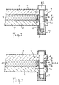
- Figure 1 shows in section part of a conventional tool after an infiltration operation.
- Figure 2 shows the tool of Figure 1 after disassembly and reassembly to achieve a new infiltration.
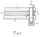
- FIG. 3 represents such a tool provided with the improvement according to the invention.
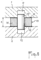
- Figures 4 and 5 show two alternative embodiments of a tool according to the invention.
- FIG. 6 represents in section a part of a tool comprising a pin for centering the plates.
- the tool partially shown in Figure 1 is composed of graphite elements. It comprises two plates 1, 2 between which is placed a preform 3 of carbon fibers which must be consolidated by infiltration of pyrocarbon in order to obtain a composite part.
- connection assemblies each comprising a bolt 4 and a nut 5 which is screwed to the threaded end thereof, with interposition of elements of wedging formed by annular spacers 6.
- connection assemblies each comprising a bolt 4 and a nut 5 which is screwed to the threaded end thereof, with interposition of elements of wedging formed by annular spacers 6.
- the pyrocarbon not only comes to infiltrate the latter, but also will be deposited on all the exposed surfaces of the tool.
- a deposit 7 is thus formed on the external faces of the plates 1, 2, on the head 4b of each bolt 4, on a portion of the internal faces of the plates 1, 2 surrounding the spacers 6, on the lateral surface of these and on nut 5 corresponding.
- the areas of contact of the plates 1, 2 with the flat bearing faces of the spacers 6, which belong to the geometric reference surfaces of the tool, as well as the surfaces of the barrel 4a of the bolts 4, of the opening are preserved. central spacers 6 and holes which are made at the ends of the plates 1, 2 to allow the passage of the bolts 4.
- the tool 1, 2, 4, 5, 6 is disassembled to allow the extraction of the part, then reassembled for the consolidation of another preform.
- FIG. 2 it may happen, due to the radial clearance existing between the barrel 4a of a bolt 4 on the one hand and the holes 1a, 2a, 6a of the plates 1, 2 and of the spacer 6, on the other hand, that a portion of the deposit 7, formed on the internal faces of the plates 1, 2 in the regions 8 adjacent to the spacer 6, is interposed, when reassembling the tool, between these faces and the corresponding faces of the spacer 6.
- annular groove 9 is hollowed out in each of the internal faces of the plates 1, 2.
- Each groove 9 surrounds the respective hole 1a, 2a of the plate 1, 2 along a path corresponding to the external contour of the spacer 6, with a width such that , taking into account the above-mentioned radial clearances, the peripheral edge of each contact face of the spacer 6 is always entirely opposite the corresponding groove.
- the deposit 7 forming in each groove 9 cannot inadvertently come between the internal faces of the plates 1, 2 and the spacer 6, whatever the positioning of the latter between the plates. This remains valid until the pyrocarbon deposits formed during successive infiltrations manage to fill the grooves 9.
- Figure 4 shows a variant in which the wedging elements are formed not by annular parts, but by straight bars 6 ′ of rectangular section.
- the grooves 9 also extend in a straight line along the edges bordering the contact faces of the bars 6 ′.
- the bars 6 ' can be an integral part of one of the plates.
- they take the form of straight edges 6 ⁇ belonging to the plate 1, the assembly possibly being consumable.
- the other plate 2 has grooves 9.
- each pin 10 is engaged in a conjugate receiving cavity 11, 12 respectively formed in one and in the other of the opposite faces of the plates 1, 2.
- each pin is surrounded by an annular sealing element 13 composed of a washer 14 of carbon felt interposed between two washers 15 of molybdenum foil (this metal is non-polluting for the atmosphere of the furnace where placed the tool, withstands high temperatures and allows easy removal of the felt washers).
- the washer 14 is strongly compressed between the plates and ensures, by a sealing effect, the protection of the pins 10, which remain free of any untimely deposit and therefore can be assembled and disassembled without difficulty.
Landscapes
- Chemical & Material Sciences (AREA)
- Engineering & Computer Science (AREA)
- Ceramic Engineering (AREA)
- Materials Engineering (AREA)
- Organic Chemistry (AREA)
- Structural Engineering (AREA)
- Chemical Kinetics & Catalysis (AREA)
- Composite Materials (AREA)
- Manufacturing & Machinery (AREA)
- General Chemical & Material Sciences (AREA)
- Mechanical Engineering (AREA)
- Metallurgy (AREA)
- Chemical Vapour Deposition (AREA)
- Manufacture Of Alloys Or Alloy Compounds (AREA)
- Clamps And Clips (AREA)
Description
- L'invention se rapporte aux outillages permettant d'effectuer l'infiltration en phase vapeur d'un matériau au sein de préformes fibreuses en vue de la fabrication de pièces composites, comprenant deux plateaux destinés à enserrer une préforme fibreuse au cours du processus d'infiltration, qui offrent des extrémités débordant de la préforme fibreuse par lesquelles ils sont solidarisés mutuellement avec un écartement convenable déterminé par des éléments de calage prévus dans la région desdites extrémités des plateaux.
- Lorsqu'on utilise un outillage de ce genre pour réaliser l'infiltration d'un matériau au sein d'une préforme fibreuse, le matériau d'infiltration forme un dépit à la surface de l'ensemble de l'outillage, qui crée une surépaisseur modifiant les dimensions de ses éléments constitutifs. Cela nécessite d'effectuer, entre chaque processus d'infiltration, un usinage d'au moins une partie desdits éléments afin de rétablir à leur valeur nominale les cotes de calage critiques qui déterminent les dimensions des pièces à réaliser.
- L'usinage intermédiaire qu'implique chaque réutilisation de l'outillage constitue une importante sujétion, d'autant plus que les formes toujours plus complexes des pièces à réaliser, donc des outillages adoptés, rendent cette opération de rénovation délicate et onéreuse.
- La présente invention a pour but de remédier à cet inconvénient.
- Selon l'invention, aux extrémités d'un plateau où celui-ci offre des faces planes de contact avec les éléments de calage, ce plateau comporte des gorges dont le tracé suit le contour des zones de contact des éléments de calage, la largeur de ces gorges étant telle que, malgré la dispersion de positionnement des éléments de calage due aux jeux de montage des éléments constitutifs de l'outillage, les armes limitant les faces d'appui des éléments de calage qui déterminent lesdites zones de contact se trouvent toujours entièrement comprises entre les bords intérieurs et extérieurs des gorges en regard.
- Grâce à la présence de ces gorges, la totalité de la surface de chaque plateau avec laquelle un élément de calage est susceptible de venir en contact reste, après une opération d'infiltration, exempte de surépaisseur due au dépôt du matériau d'infiltration formé dans cette région. Les gorges assurent ainsi la protection des surfaces de référence géométrique de l'outillage et permettent de renouveler le montage de ce dernier sans risque qu'un élément de calage vienne s'appuyer sur le dépôt résultant d'une infiltration précédente, et non sur la surface de calage proprement dite d'un plateau. Cela procure une notable augmentation de la durée de vie de l'outillage sans rénovation intermédiaire par usinage, laquelle ne s'achève qu'au complet remplissage des gorges par les dépôts successifs formés durant de multiples processus d'infiltration.
- Lorsque l'outillage est doté de pions de centrage destinés à assurer un positionnement précis des plateaux, chaque pion étant fixé, éventuellement de manière amovible, à l'un des plateaux et traversant l'intervalle qui les sépare pour aller s'emboîter dans une cavité de réception pratiquée dans l'autre plateau, il convient de prévoir en outre, autour de chaque pion, un élément annulaire qui se trouve comprimé entre les deux plateaux lorsque ceux-ci sont amenés à leur écartement convenable et assure la protection du pion par un effet d'étanchéité en le préservant de tout dépôt, lors du processus d'infiltration, qui risquerait d'affecter les possibilités de démontage et de remontage du pion. Cet élément annulaire peut avantageusement être composé d'une rondelle épaisse de feutre de carbone flanquée d'une paire de rondelles minces de métal, par exemple de molybdène.
- L'invention s'applique aux outillages pour infiltration de pyrocarbone ou de tout autre matériau constitutif d'une matrice au sein d'une préforme fibreuse et susceptible d'être infiltré en phase vapeur, tel que le carbure de silicium SiC.
- D'autres particularités et avantages de l'invention ressortiront de la description qui va suivre, en regard des dessins annexés, d'exemples de réalisation non limitatifs.
- La figure 1 représente en coupe une partie d'un outillage classique après une opération d'infiltration.
- La figure 2 représente l'outillage de la figure 1 après démontage puis remontage pour réalisation d'une nouvelle infiltration.
- La figure 3 représente un tel outillage muni du perfectionnement selon l'invention.
- Les figures 4 et 5 représentent deux variantes de réalisation d'un outillage selon l'invention.
- La figure 6 représente en coupe une partie d'un outillage comprenant un pion de centrage des plateaux.
- L'outillage représenté partiellement à la figure 1 est composé d'éléments en graphite. Il comprend deux plateaux 1, 2 entre lesquels est placée une préforme 3 de fibres de carbone qui doit être consolidée par infiltration de pyrocarbone en vue de l'obtention d'une pièce composite.
- A leurs extrémités débordant de la préforme fibreuse 3, les plateaux 1, 2 sont réunis par des ensembles de liaison comprenant chacun un boulon 4 et un écrou 5 qui se visse à l'extrémité filetée de celui-ci, avec interposition d'éléments de calage constitués par des entretoises annulaires 6. Chacune de ces dernières, engagée sur le fût 4a d'un boulon 4, détermine par son épaisseur, c'est-à-dire par la distance qui sépare ses deux faces annulaires planes et parallèles, l'écartement e des plateaux 1, 2 qui fixe l'épaisseur souhaitée pour la pièce composite à réaliser.
- Lors de l'opération de consolidation de la préforme fibreuse 3, le pyrocarbone non seulement vient infiltrer celle-ci, mais également va se déposer sur toutes les surfaces exposées de l'outillage. Un dépôt 7 se forme ainsi sur les faces externes des plateaux 1, 2, sur la tête 4b de chaque boulon 4, sur une portion des faces internes des plateaux 1, 2 entourant les entretoises 6, sur la surface latérale de celles-ci et sur l'écrou 5 correspondant. Restent toutefois préservées les zones de contact des plateaux 1, 2 avec les faces d'appui planes des entretoises 6, qui appartiennent aux surfaces de référence géométrique de l'outillage, ainsi que les surfaces du fût 4a des boulons 4, de l'ouverture centrale des entretoises 6 et des trous qui sont pratiqués aux extrémités des plateaux 1, 2 pour permettre le passage des boulons 4.
- Après achèvement du processus d'infiltration, l'outillage 1, 2, 4, 5, 6 est démonté pour permettre l'extraction de la pièce, puis remonté en vue de la consolidation d'une autre préforme. Comme le montre la figure 2, il peut arriver, en raison du jeu radial existant entre le fût 4a d'un boulon 4 d'une part et les trous 1a, 2a, 6a des plateaux 1, 2 et de l'entretoise 6, d'autre part, qu'une portion du dépôt 7, formée sur les faces internes des plateaux 1, 2 dans les régions 8 voisines de l'entretoise 6, s'interpose, au remontage de l'outillage, entre ces faces et les faces correspondantes de l'entretoise 6. Il en résulte un écartement exagéré e + Δ e des faces internes des plateaux, conduisant à une pièce d'épaisseur incorrecte.
- L'outillage représenté à la figure 3 a été aménagé pour éviter pareille éventualité. Une gorge annulaire 9 est creusée dans chacune des faces internes des plateaux 1, 2. Chaque gorge 9 entoure le trou 1a, 2a du plateau 1, 2 respectif suivant un tracé correspondant au contour extérieur de l'entretoise 6, avec une largeur telle que, compte tenu des jeux radiaux précités, l'arête périphérique de chaque face de contact de l'entretoise 6 se trouve toujours entièrement en regard de la gorge correspondante. Ainsi, le dépôt 7 se formant dans chaque gorge 9 ne peut venir s'interposer intempestivement entre les faces internes des plateaux 1, 2 et l'entretoise 6, quel que soit le positionnement de celle-ci entre les plateaux. Ceci reste valable jusqu'à ce que les dépôts de pyrocarbone formés lors d'infiltrations successives parviennent à combler les gorges 9.
- La figure 4 montre une variante dans laquelle les éléments de calage sont constitués non pas par des pièces annulaires, mais par des barres rectilignes 6′ de section rectangulaire. Dans ce cas, les gorges 9 s'étendent également en ligne droite le long des arêtes bordant les faces de contact des barres 6′.
- Selon la figure 5, les barres 6′ peuvent faire partie intégrante de l'un des plateaux. Dans le présent exemple, elles prennent la forme de rebords rectilignes 6˝ appartenant au plateau 1, l'ensemble pouvant être consommable. Ici, seul l'autre plateau 2 comporte des gorges 9.
- Afin d'assurer un positionnement précis des plateaux 1 et 2 l'un par rapport à l'autre, ceux-ci sont munis de pions de centrage 10 dont l'un est représenté à la figure 6. Chaque pion 10 est engagé dans une cavité de réception conjuguée 11, 12 respectivement ménagée dans l'une et dans l'autre des faces en regard des plateaux 1, 2. Afin d'éviter qu'un dépôt de pyrocarbone se forme sur les pions 10 et les parties avoisinantes des faces internes des plateaux, chaque pion est entouré d'un élément d'étanchéité annulaire 13 composé d'une rondelle 14 de feutre de carbone interposée entre deux rondelles 15 de clinquant de molybdène (ce métal est non polluant pour l'atmosphère du four où est placé l'outillage, résiste aux hautes températures et permet un décollement facile des rondelles de feutre). Lorsque les plateaux 1, 2 sont mis à l'écartement e déterminé par les entretoises de calage en épaisseur, la rondelle 14 se trouve fortement comprimée entre les plateaux et assure, par un effet d'étanchéité, la protection des pions 10, qui restent vierges de tout dépôt intempestif et, de ce fait, peuvent être montés et démontés sans difficulté.
Claims (5)
- Outillage permettant d'effectuer l'infiltration en phase vapeur d'un matériau au sein de préformes fibreuses en vue de la fabrication de pièces composites, comprenant deux plateaux destinés à enserrer une préforme fibreuse au cours du processus d'infiltration, qui offrent des extrémités débordant de la préforme fibreuse par lesquelles ils sont solidarisés mutuellement avec un écartement convenable déterminé par des éléments de calage prévus dans la région desdites extrémités des plateaux,
caractérisé par le fait que, aux extrémités d'un plateau (2) où celui-ci offre des faces planes de contact avec les éléments de calage (6; 6′; 6˝), ce plateau comporte des gorges (9) dont le tracé suit le contour des zones de contact des éléments de calage, la largeur de ces gorges étant telle que, malgré la dispersion de positionnement des éléments de calage due aux jeux de montage des éléments constitutifs de l'outillage, les arêtes limitant les faces d'appui des éléments de calage qui déterminent lesdites zones de contact se trouvent toujours entièrement comprises entre les bords intérieurs et extérieurs des gorges en regard. - Outillage selon la revendication 1, caractérisé par le fait que les éléments de calage sont constitués par des entretoises (6; 6′) interposées entre les faces d'extrémités des plateaux (1, 2), lesquels comportent tous deux des gorges (9) dans lesdites faces.
- Outillage selon la revendication 1, caractérisé par le fait que les éléments de calage sont constitués par des rebords (6˝) appartenant à l'un (1) des plateaux, seul l'autre plateau (2) étant doté de gorges (9) dans ses faces d'extrémités.
- Outillage selon l'une quelconque des revendications 1 à 3, caractérisé par le fait qu'il est doté de pions de centrage (10) assurant un positionnement précis des plateaux (1, 2), chaque pion étant fixé, éventuellement de manière amovible, à l'un des plateaux et traversant l'intervalle qui les sépare pour aller s'emboîter dans une cavité de réception pratiquée dans l'autre plateau, et qu'autour de chaque pion (10) est prévu un élément annulaire (13) qui se trouve comprimé entre les deux plateaux lorsque ceux-ci sont amenés à leur écartement (e) convenable et assure la protection du pion par un effet d'étanchéité.
- Outillage selon la revendication 4, caractérisé par le fait que ledit élément annulaire (13) est composé d'une rondelle épaisse (14) de feutre de carbone flanquée d'une paire de rondelles minces (15) de métal, par exemple de molybdène.
Applications Claiming Priority (2)
| Application Number | Priority Date | Filing Date | Title |
|---|---|---|---|
| FR8909336 | 1989-07-11 | ||
| FR8909336A FR2649765B1 (fr) | 1989-07-11 | 1989-07-11 | Perfectionnement aux outillages permettant d'effectuer l'infiltration en phase vapeur d'un materiau au sein de preformes fibreuses, en vue de la fabrication de pieces composites |
Publications (2)
| Publication Number | Publication Date |
|---|---|
| EP0408435A1 EP0408435A1 (fr) | 1991-01-16 |
| EP0408435B1 true EP0408435B1 (fr) | 1992-12-30 |
Family
ID=9383683
Family Applications (1)
| Application Number | Title | Priority Date | Filing Date |
|---|---|---|---|
| EP90401972A Expired - Lifetime EP0408435B1 (fr) | 1989-07-11 | 1990-07-09 | Perfectionnement aux outillages permettant d'effectuer l'infiltration en phase vapeur d'un matériau au sein de préformes fibreuses, en vue de la fabrication de pièces composites |
Country Status (4)
| Country | Link |
|---|---|
| US (1) | US5048807A (fr) |
| EP (1) | EP0408435B1 (fr) |
| DE (1) | DE69000699T2 (fr) |
| FR (1) | FR2649765B1 (fr) |
Families Citing this family (5)
| Publication number | Priority date | Publication date | Assignee | Title |
|---|---|---|---|---|
| WO2010059164A1 (fr) * | 2008-11-21 | 2010-05-27 | Hewlett-Packard Development Company, L.P. | Appareil et procédé de serrage de fibre de carbone |
| US11326255B2 (en) * | 2013-02-07 | 2022-05-10 | Uchicago Argonne, Llc | ALD reactor for coating porous substrates |
| US11111578B1 (en) | 2020-02-13 | 2021-09-07 | Uchicago Argonne, Llc | Atomic layer deposition of fluoride thin films |
| US12065738B2 (en) | 2021-10-22 | 2024-08-20 | Uchicago Argonne, Llc | Method of making thin films of sodium fluorides and their derivatives by ALD |
| US11901169B2 (en) | 2022-02-14 | 2024-02-13 | Uchicago Argonne, Llc | Barrier coatings |
Family Cites Families (8)
| Publication number | Priority date | Publication date | Assignee | Title |
|---|---|---|---|---|
| US1878850A (en) * | 1929-03-16 | 1932-09-20 | Hilgers John | Protective device for tables |
| US2542719A (en) * | 1944-10-19 | 1951-02-20 | Sprague Electric Co | Clamp for making mica condensers |
| US2684525A (en) * | 1951-03-12 | 1954-07-27 | Richard A Dominguez | Valve reconditioning jig apparatus |
| AT238691B (de) * | 1961-09-13 | 1965-02-25 | Oesterr Studien Atomenergie | Verfahren zur Herstellung genau dimensionierter, aus Fasern aufgebauter Kohle- oder Graphitformkörper |
| US3991248A (en) * | 1972-03-28 | 1976-11-09 | Ducommun Incorporated | Fiber reinforced composite product |
| FR2334495A1 (fr) * | 1975-12-08 | 1977-07-08 | Europ Propulsion | Outillage de rigidification de pieces a base de fibres de carbone et/ou graphite |
| FR2433003A1 (fr) * | 1978-08-08 | 1980-03-07 | Commissariat Energie Atomique | Procede de fabrication d'un materiau renforce par une structure textile tridimensionnelle |
| US4824066A (en) * | 1983-04-11 | 1989-04-25 | Smith S Gregory | Apparatus for aiding in the storing and preserving of donor corneas |
-
1989
- 1989-07-11 FR FR8909336A patent/FR2649765B1/fr not_active Expired - Fee Related
-
1990
- 1990-07-09 DE DE9090401972T patent/DE69000699T2/de not_active Expired - Fee Related
- 1990-07-09 US US07/550,318 patent/US5048807A/en not_active Expired - Fee Related
- 1990-07-09 EP EP90401972A patent/EP0408435B1/fr not_active Expired - Lifetime
Also Published As
| Publication number | Publication date |
|---|---|
| US5048807A (en) | 1991-09-17 |
| EP0408435A1 (fr) | 1991-01-16 |
| DE69000699T2 (de) | 1993-04-29 |
| FR2649765A1 (fr) | 1991-01-18 |
| DE69000699D1 (de) | 1993-02-11 |
| FR2649765B1 (fr) | 1991-10-25 |
Similar Documents
| Publication | Publication Date | Title |
|---|---|---|
| EP3737837B1 (fr) | Ensemble d'anneau de turbine | |
| EP3870807B1 (fr) | Ensemble d'anneau de turbine à appuis rectilignes bombés | |
| CA2986661C (fr) | Ensemble d'anneau de turbine | |
| EP3781792B1 (fr) | Distributeur en cmc avec reprise d'effort par une pince étanche | |
| EP3908738B1 (fr) | Procede de montage et de demontage d'un ensemble d'anneau de turbine | |
| EP0068923B1 (fr) | Dispositif de verrouillage d'une aube de rotor de turbomachine | |
| EP3899208B1 (fr) | Ensemble d'anneau de turbine | |
| FR2504980A1 (fr) | Montage de palier, en particulier pour turbomachines | |
| WO2011161371A1 (fr) | Roue mobile a aubes en materiau composite pour moteur a turbine a gaz a liaison pied d'aube/disque par serrage | |
| FR2990368A1 (fr) | Outillage de fabrication d'un noyau de fonderie pour une aube de turbomachine | |
| FR3086327A1 (fr) | Ensemble pour une turbine de turbomachine | |
| FR2941487A1 (fr) | Aube de turbomachine en materiau composite a pied renforce | |
| EP0408435B1 (fr) | Perfectionnement aux outillages permettant d'effectuer l'infiltration en phase vapeur d'un matériau au sein de préformes fibreuses, en vue de la fabrication de pièces composites | |
| FR2954266A1 (fr) | Jeu de direction de cycle a goupille et cycle comportant un tel jeu de direction | |
| EP2315642A1 (fr) | Procede de reparation ou de reprise d'un disque de turbomachine et disque de turbomachine repare ou repris | |
| FR2744169A1 (fr) | Dispositif de fixation par rivetage des aubes mobiles sur la roue mobile, notamment d'une turbine d'un moteur a turbine a gaz | |
| FR3021671A1 (fr) | Conformateur pour la consolidation et/ou la densification en phase gazeuse d'une preforme fibreuse | |
| FR3080146A1 (fr) | Distributeur en cmc avec reprise d'effort | |
| FR3017321A1 (fr) | Noyau de moule d'injection pour la realisation d'une piece en materiau composite ayant un caisson ferme | |
| FR2566859A1 (fr) | Frein a disque et procede pour son assemblage | |
| EP0399879A1 (fr) | Distributeur de turbine pour turbo-réacteur et son procédé de fabrication | |
| EP2361165B1 (fr) | Canon de guidage flexible pour machine-outil | |
| WO2023131759A1 (fr) | Turbine pour turbomachine | |
| FR3106152A1 (fr) | Ensemble d’anneau de turbine avec flasques indexés | |
| EP0013189B1 (fr) | Broche à éléments de coupe rapportés |
Legal Events
| Date | Code | Title | Description |
|---|---|---|---|
| PUAI | Public reference made under article 153(3) epc to a published international application that has entered the european phase |
Free format text: ORIGINAL CODE: 0009012 |
|
| AK | Designated contracting states |
Kind code of ref document: A1 Designated state(s): DE GB |
|
| 17P | Request for examination filed |
Effective date: 19901221 |
|
| 17Q | First examination report despatched |
Effective date: 19920127 |
|
| GRAA | (expected) grant |
Free format text: ORIGINAL CODE: 0009210 |
|
| AK | Designated contracting states |
Kind code of ref document: B1 Designated state(s): DE GB |
|
| GBT | Gb: translation of ep patent filed (gb section 77(6)(a)/1977) |
Effective date: 19921229 |
|
| REF | Corresponds to: |
Ref document number: 69000699 Country of ref document: DE Date of ref document: 19930211 |
|
| PLBE | No opposition filed within time limit |
Free format text: ORIGINAL CODE: 0009261 |
|
| STAA | Information on the status of an ep patent application or granted ep patent |
Free format text: STATUS: NO OPPOSITION FILED WITHIN TIME LIMIT |
|
| 26N | No opposition filed | ||
| PGFP | Annual fee paid to national office [announced via postgrant information from national office to epo] |
Ref country code: GB Payment date: 19990713 Year of fee payment: 10 |
|
| PGFP | Annual fee paid to national office [announced via postgrant information from national office to epo] |
Ref country code: DE Payment date: 19990715 Year of fee payment: 10 |
|
| REG | Reference to a national code |
Ref country code: GB Ref legal event code: 732E |
|
| PG25 | Lapsed in a contracting state [announced via postgrant information from national office to epo] |
Ref country code: GB Free format text: LAPSE BECAUSE OF NON-PAYMENT OF DUE FEES Effective date: 20000709 |
|
| GBPC | Gb: european patent ceased through non-payment of renewal fee |
Effective date: 20000709 |
|
| PG25 | Lapsed in a contracting state [announced via postgrant information from national office to epo] |
Ref country code: DE Free format text: LAPSE BECAUSE OF NON-PAYMENT OF DUE FEES Effective date: 20010501 |