EP0408435B1 - Vervollkommnung von Werkzeugen für die Dampfphaseninfiltration eines Materials ins innere faseriger Vorformen im Hinblick auf die Herstellung von Verbundwerkstoffen - Google Patents
Vervollkommnung von Werkzeugen für die Dampfphaseninfiltration eines Materials ins innere faseriger Vorformen im Hinblick auf die Herstellung von Verbundwerkstoffen Download PDFInfo
- Publication number
- EP0408435B1 EP0408435B1 EP90401972A EP90401972A EP0408435B1 EP 0408435 B1 EP0408435 B1 EP 0408435B1 EP 90401972 A EP90401972 A EP 90401972A EP 90401972 A EP90401972 A EP 90401972A EP 0408435 B1 EP0408435 B1 EP 0408435B1
- Authority
- EP
- European Patent Office
- Prior art keywords
- plates
- tool
- fact
- blocking elements
- faces
- Prior art date
- Legal status (The legal status is an assumption and is not a legal conclusion. Google has not performed a legal analysis and makes no representation as to the accuracy of the status listed.)
- Expired - Lifetime
Links
Images

Classifications
-
- C—CHEMISTRY; METALLURGY
- C04—CEMENTS; CONCRETE; ARTIFICIAL STONE; CERAMICS; REFRACTORIES
- C04B—LIME, MAGNESIA; SLAG; CEMENTS; COMPOSITIONS THEREOF, e.g. MORTARS, CONCRETE OR LIKE BUILDING MATERIALS; ARTIFICIAL STONE; CERAMICS; REFRACTORIES; TREATMENT OF NATURAL STONE
- C04B41/00—After-treatment of mortars, concrete, artificial stone or ceramics; Treatment of natural stone
- C04B41/45—Coating or impregnating, e.g. injection in masonry, partial coating of green or fired ceramics, organic coating compositions for adhering together two concrete elements
- C04B41/4505—Coating or impregnating, e.g. injection in masonry, partial coating of green or fired ceramics, organic coating compositions for adhering together two concrete elements characterised by the method of application
- C04B41/4529—Coating or impregnating, e.g. injection in masonry, partial coating of green or fired ceramics, organic coating compositions for adhering together two concrete elements characterised by the method of application applied from the gas phase
-
- C—CHEMISTRY; METALLURGY
- C04—CEMENTS; CONCRETE; ARTIFICIAL STONE; CERAMICS; REFRACTORIES
- C04B—LIME, MAGNESIA; SLAG; CEMENTS; COMPOSITIONS THEREOF, e.g. MORTARS, CONCRETE OR LIKE BUILDING MATERIALS; ARTIFICIAL STONE; CERAMICS; REFRACTORIES; TREATMENT OF NATURAL STONE
- C04B35/00—Shaped ceramic products characterised by their composition; Ceramics compositions; Processing powders of inorganic compounds preparatory to the manufacturing of ceramic products
- C04B35/71—Ceramic products containing macroscopic reinforcing agents
- C04B35/78—Ceramic products containing macroscopic reinforcing agents containing non-metallic materials
- C04B35/80—Fibres, filaments, whiskers, platelets, or the like
- C04B35/83—Carbon fibres in a carbon matrix
-
- C—CHEMISTRY; METALLURGY
- C04—CEMENTS; CONCRETE; ARTIFICIAL STONE; CERAMICS; REFRACTORIES
- C04B—LIME, MAGNESIA; SLAG; CEMENTS; COMPOSITIONS THEREOF, e.g. MORTARS, CONCRETE OR LIKE BUILDING MATERIALS; ARTIFICIAL STONE; CERAMICS; REFRACTORIES; TREATMENT OF NATURAL STONE
- C04B41/00—After-treatment of mortars, concrete, artificial stone or ceramics; Treatment of natural stone
- C04B41/80—After-treatment of mortars, concrete, artificial stone or ceramics; Treatment of natural stone of only ceramics
- C04B41/81—Coating or impregnation
-
- C—CHEMISTRY; METALLURGY
- C23—COATING METALLIC MATERIAL; COATING MATERIAL WITH METALLIC MATERIAL; CHEMICAL SURFACE TREATMENT; DIFFUSION TREATMENT OF METALLIC MATERIAL; COATING BY VACUUM EVAPORATION, BY SPUTTERING, BY ION IMPLANTATION OR BY CHEMICAL VAPOUR DEPOSITION, IN GENERAL; INHIBITING CORROSION OF METALLIC MATERIAL OR INCRUSTATION IN GENERAL
- C23C—COATING METALLIC MATERIAL; COATING MATERIAL WITH METALLIC MATERIAL; SURFACE TREATMENT OF METALLIC MATERIAL BY DIFFUSION INTO THE SURFACE, BY CHEMICAL CONVERSION OR SUBSTITUTION; COATING BY VACUUM EVAPORATION, BY SPUTTERING, BY ION IMPLANTATION OR BY CHEMICAL VAPOUR DEPOSITION, IN GENERAL
- C23C16/00—Chemical coating by decomposition of gaseous compounds, without leaving reaction products of surface material in the coating, i.e. chemical vapour deposition [CVD] processes
- C23C16/44—Chemical coating by decomposition of gaseous compounds, without leaving reaction products of surface material in the coating, i.e. chemical vapour deposition [CVD] processes characterised by the method of coating
- C23C16/458—Chemical coating by decomposition of gaseous compounds, without leaving reaction products of surface material in the coating, i.e. chemical vapour deposition [CVD] processes characterised by the method of coating characterised by the method used for supporting substrates in the reaction chamber
-
- C—CHEMISTRY; METALLURGY
- C04—CEMENTS; CONCRETE; ARTIFICIAL STONE; CERAMICS; REFRACTORIES
- C04B—LIME, MAGNESIA; SLAG; CEMENTS; COMPOSITIONS THEREOF, e.g. MORTARS, CONCRETE OR LIKE BUILDING MATERIALS; ARTIFICIAL STONE; CERAMICS; REFRACTORIES; TREATMENT OF NATURAL STONE
- C04B2235/00—Aspects relating to ceramic starting mixtures or sintered ceramic products
- C04B2235/70—Aspects relating to sintered or melt-casted ceramic products
- C04B2235/94—Products characterised by their shape
Definitions
- the invention relates to tools for carrying out vapor phase infiltration of a material within fibrous preforms for the manufacture of composite parts, comprising two plates intended to enclose a fibrous preform during the process of infiltration, which offer ends protruding from the fibrous preform by which they are mutually secured with a suitable spacing determined by wedging elements provided in the region of said ends of the plates.
- the infiltration material forms a spite on the surface of the whole of the tool, which creates an extra thickness modifying the dimensions of its constituent elements. This requires performing, between each infiltration process, a machining of at least a portion of said elements in order to restore to their nominal value the critical setting dimensions which determine the dimensions of the parts to be produced.
- the object of the present invention is to remedy this drawback.
- this plate comprises grooves, the outline of which follows the contour of the contact zones of the wedging elements, the width of these grooves being such that, despite the dispersion of positioning of the wedging elements due to the mounting clearances of the components of the tool, the arms limiting the bearing faces wedging elements which determine said contact zones are always entirely comprised between the inner and outer edges of the facing grooves.
- each plate with which a wedging element is liable to come into contact remains, after an infiltration operation, free of excess thickness due to the deposition of the infiltration material formed in this region.
- the grooves thus ensure the protection of the geometric reference surfaces of the tool and allow the assembly of the latter to be renewed without the risk of a wedging element coming to bear on the deposit resulting from a previous infiltration, and not on the wedging surface proper of a plate. This provides a significant increase in the life of the tool without intermediate renovation by machining, which only ends when the grooves are completely filled with successive deposits formed during multiple infiltration processes.
- each pin being fixed, optionally in a removable manner, to one of the plates and crossing the interval which separates them to go and fit into a receiving cavity formed in the other plate, it is also necessary to provide, around each pin, an annular element which is compressed between the two plates when the latter are brought to their proper spacing and ensures the protection of the pin by a sealing effect by preserving it from any deposit during the infiltration process, which could affect the possibilities of dismantling and reassembling the pin.
- This annular element can advantageously be composed of a thick washer of carbon felt flanked by a pair of thin washers of metal, for example of molybdenum.
- the invention applies to tools for infiltration of pyrocarbon or any other material constituting a matrix within a fibrous preform and capable of being infiltrated in the vapor phase, such as silicon carbide SiC.
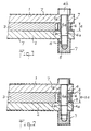
- Figure 1 shows in section part of a conventional tool after an infiltration operation.
- Figure 2 shows the tool of Figure 1 after disassembly and reassembly to achieve a new infiltration.
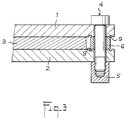
- FIG. 3 represents such a tool provided with the improvement according to the invention.
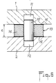
- Figures 4 and 5 show two alternative embodiments of a tool according to the invention.
- FIG. 6 represents in section a part of a tool comprising a pin for centering the plates.
- the tool partially shown in Figure 1 is composed of graphite elements. It comprises two plates 1, 2 between which is placed a preform 3 of carbon fibers which must be consolidated by infiltration of pyrocarbon in order to obtain a composite part.
- connection assemblies each comprising a bolt 4 and a nut 5 which is screwed to the threaded end thereof, with interposition of elements of wedging formed by annular spacers 6.
- connection assemblies each comprising a bolt 4 and a nut 5 which is screwed to the threaded end thereof, with interposition of elements of wedging formed by annular spacers 6.
- the pyrocarbon not only comes to infiltrate the latter, but also will be deposited on all the exposed surfaces of the tool.
- a deposit 7 is thus formed on the external faces of the plates 1, 2, on the head 4b of each bolt 4, on a portion of the internal faces of the plates 1, 2 surrounding the spacers 6, on the lateral surface of these and on nut 5 corresponding.
- the areas of contact of the plates 1, 2 with the flat bearing faces of the spacers 6, which belong to the geometric reference surfaces of the tool, as well as the surfaces of the barrel 4a of the bolts 4, of the opening are preserved. central spacers 6 and holes which are made at the ends of the plates 1, 2 to allow the passage of the bolts 4.
- the tool 1, 2, 4, 5, 6 is disassembled to allow the extraction of the part, then reassembled for the consolidation of another preform.
- FIG. 2 it may happen, due to the radial clearance existing between the barrel 4a of a bolt 4 on the one hand and the holes 1a, 2a, 6a of the plates 1, 2 and of the spacer 6, on the other hand, that a portion of the deposit 7, formed on the internal faces of the plates 1, 2 in the regions 8 adjacent to the spacer 6, is interposed, when reassembling the tool, between these faces and the corresponding faces of the spacer 6.
- annular groove 9 is hollowed out in each of the internal faces of the plates 1, 2.
- Each groove 9 surrounds the respective hole 1a, 2a of the plate 1, 2 along a path corresponding to the external contour of the spacer 6, with a width such that , taking into account the above-mentioned radial clearances, the peripheral edge of each contact face of the spacer 6 is always entirely opposite the corresponding groove.
- the deposit 7 forming in each groove 9 cannot inadvertently come between the internal faces of the plates 1, 2 and the spacer 6, whatever the positioning of the latter between the plates. This remains valid until the pyrocarbon deposits formed during successive infiltrations manage to fill the grooves 9.
- Figure 4 shows a variant in which the wedging elements are formed not by annular parts, but by straight bars 6 ′ of rectangular section.
- the grooves 9 also extend in a straight line along the edges bordering the contact faces of the bars 6 ′.
- the bars 6 ' can be an integral part of one of the plates.
- they take the form of straight edges 6 ⁇ belonging to the plate 1, the assembly possibly being consumable.
- the other plate 2 has grooves 9.
- each pin 10 is engaged in a conjugate receiving cavity 11, 12 respectively formed in one and in the other of the opposite faces of the plates 1, 2.
- each pin is surrounded by an annular sealing element 13 composed of a washer 14 of carbon felt interposed between two washers 15 of molybdenum foil (this metal is non-polluting for the atmosphere of the furnace where placed the tool, withstands high temperatures and allows easy removal of the felt washers).
- the washer 14 is strongly compressed between the plates and ensures, by a sealing effect, the protection of the pins 10, which remain free of any untimely deposit and therefore can be assembled and disassembled without difficulty.
Landscapes
- Chemical & Material Sciences (AREA)
- Engineering & Computer Science (AREA)
- Ceramic Engineering (AREA)
- Organic Chemistry (AREA)
- Materials Engineering (AREA)
- Structural Engineering (AREA)
- Chemical Kinetics & Catalysis (AREA)
- Metallurgy (AREA)
- Mechanical Engineering (AREA)
- General Chemical & Material Sciences (AREA)
- Composite Materials (AREA)
- Manufacturing & Machinery (AREA)
- Chemical Vapour Deposition (AREA)
- Clamps And Clips (AREA)
- Manufacture Of Alloys Or Alloy Compounds (AREA)
Claims (5)
- Werkzeug für die Dampfphaseninfiltration eines Materials ins Innere faseriger Vorformen im Hinblick auf die Herstellung von Verbundwerkstoffen, umfassend zwei Platten, die eine faserige Vorform während des Infiltrationsvorgangs einspannen sollen, und die Enden besitzen, welche über die faserige Vorform hinausragen und durch welche sie fest aneinander befestigt sind, und zwar in entsprechendem Abstand, der durch Keilstücke bestimmt wird, die im Bereich der Plattenenden vorgesehen sind,
dadurch gekennzeichnet, daß eine Platte (2) an ihren Enden, an denen sie über ebene Kontaktflächen mit den Keilstücken (6; 6′; 6˝) verfügt, Rillen (9) aufweist, die dem Umriß der Kontaktzonen der Keilstücke folgen, wobei die Breite dieser Rillen auch trotz der weiten Positionierung der Keilstücke, die durch das Montagespiel der Bestandteile des Werkzeugs entsteht, dadurch bestimmt wird, daß die Kanten, die die Auflageseiten der Keilstücke bilden, die die genannten Kontaktzonen bestimmen, sich immer vollkommen zwischen dem Innen- und Außenrand der sich gegenüberliegenden Rillen befinden. - Werkzeug gemäß Anspruch 1, dadurch gekennzeichnet, daß die Keilstücke aus Distanzstücken (6; 6′) bestehen, die zwischen die Seiten der Enden der Platten (1,2) gesetzt werden, von denen beide Rillen (9) in den besagten Seiten aufweisen.
- Werkzeug gemäß Anspruch 1, dadurch gekennzeichnet, daß die Keilstücke aus Leisten (6˝) bestehen, die zu einer der beiden Platten (1) gehören, wobei nur die andere Platte (2) an den Seiten der Enden über Rillen (9) verfügt.
- Werkzeug gemäß einem der Ansprüche 1 bis 3, dadurch gekennzeichnet, daß es über Zentrierstifte (10) verfügt, die die genaue Positionierung der Platten (1, 2) sicherstellen, wobei jeder Stift, eventuell herausnehmbar, an einer der Platten befestigt ist und zwischen beiden Platten durchgesteckt wird und in eine Aufnahmehöhlung faßt, die in der anderen Platte vorgesehen ist, und daß um jeden Stift (10) herum ein ringförmiges Element (13) vorgesehen ist, das zwischen den beiden Platten zusammengedrückt wird, wenn diese in den richtigen Abstand (e) voneinander gebracht werden, und das durch einen Abdichteffekt den Stift schützt.
- Werkzeug gemäß Anspruch 4, dadurch gekennzeichnet, daß das besagte ringförmige Element (13) aus einer dicken Kohlenstoffilzscheibe (14) besteht, die flankiert ist von einem Paar dünner Scheiben (15) aus Metall, beispielsweise aus Molybdän.
Applications Claiming Priority (2)
| Application Number | Priority Date | Filing Date | Title |
|---|---|---|---|
| FR8909336A FR2649765B1 (fr) | 1989-07-11 | 1989-07-11 | Perfectionnement aux outillages permettant d'effectuer l'infiltration en phase vapeur d'un materiau au sein de preformes fibreuses, en vue de la fabrication de pieces composites |
| FR8909336 | 1989-07-11 |
Publications (2)
| Publication Number | Publication Date |
|---|---|
| EP0408435A1 EP0408435A1 (de) | 1991-01-16 |
| EP0408435B1 true EP0408435B1 (de) | 1992-12-30 |
Family
ID=9383683
Family Applications (1)
| Application Number | Title | Priority Date | Filing Date |
|---|---|---|---|
| EP90401972A Expired - Lifetime EP0408435B1 (de) | 1989-07-11 | 1990-07-09 | Vervollkommnung von Werkzeugen für die Dampfphaseninfiltration eines Materials ins innere faseriger Vorformen im Hinblick auf die Herstellung von Verbundwerkstoffen |
Country Status (4)
| Country | Link |
|---|---|
| US (1) | US5048807A (de) |
| EP (1) | EP0408435B1 (de) |
| DE (1) | DE69000699T2 (de) |
| FR (1) | FR2649765B1 (de) |
Families Citing this family (5)
| Publication number | Priority date | Publication date | Assignee | Title |
|---|---|---|---|---|
| WO2010059164A1 (en) * | 2008-11-21 | 2010-05-27 | Hewlett-Packard Development Company, L.P. | Carbon fiber clamping apparatus and method |
| US11326255B2 (en) * | 2013-02-07 | 2022-05-10 | Uchicago Argonne, Llc | ALD reactor for coating porous substrates |
| US11111578B1 (en) | 2020-02-13 | 2021-09-07 | Uchicago Argonne, Llc | Atomic layer deposition of fluoride thin films |
| US12065738B2 (en) | 2021-10-22 | 2024-08-20 | Uchicago Argonne, Llc | Method of making thin films of sodium fluorides and their derivatives by ALD |
| US11901169B2 (en) | 2022-02-14 | 2024-02-13 | Uchicago Argonne, Llc | Barrier coatings |
Family Cites Families (8)
| Publication number | Priority date | Publication date | Assignee | Title |
|---|---|---|---|---|
| US1878850A (en) * | 1929-03-16 | 1932-09-20 | Hilgers John | Protective device for tables |
| US2542719A (en) * | 1944-10-19 | 1951-02-20 | Sprague Electric Co | Clamp for making mica condensers |
| US2684525A (en) * | 1951-03-12 | 1954-07-27 | Richard A Dominguez | Valve reconditioning jig apparatus |
| AT238691B (de) * | 1961-09-13 | 1965-02-25 | Oesterr Studien Atomenergie | Verfahren zur Herstellung genau dimensionierter, aus Fasern aufgebauter Kohle- oder Graphitformkörper |
| US3991248A (en) * | 1972-03-28 | 1976-11-09 | Ducommun Incorporated | Fiber reinforced composite product |
| FR2334495A1 (fr) * | 1975-12-08 | 1977-07-08 | Europ Propulsion | Outillage de rigidification de pieces a base de fibres de carbone et/ou graphite |
| FR2433003A1 (fr) * | 1978-08-08 | 1980-03-07 | Commissariat Energie Atomique | Procede de fabrication d'un materiau renforce par une structure textile tridimensionnelle |
| US4824066A (en) * | 1983-04-11 | 1989-04-25 | Smith S Gregory | Apparatus for aiding in the storing and preserving of donor corneas |
-
1989
- 1989-07-11 FR FR8909336A patent/FR2649765B1/fr not_active Expired - Fee Related
-
1990
- 1990-07-09 DE DE9090401972T patent/DE69000699T2/de not_active Expired - Fee Related
- 1990-07-09 US US07/550,318 patent/US5048807A/en not_active Expired - Fee Related
- 1990-07-09 EP EP90401972A patent/EP0408435B1/de not_active Expired - Lifetime
Also Published As
| Publication number | Publication date |
|---|---|
| FR2649765A1 (fr) | 1991-01-18 |
| US5048807A (en) | 1991-09-17 |
| EP0408435A1 (de) | 1991-01-16 |
| DE69000699D1 (de) | 1993-02-11 |
| FR2649765B1 (fr) | 1991-10-25 |
| DE69000699T2 (de) | 1993-04-29 |
Similar Documents
| Publication | Publication Date | Title |
|---|---|---|
| EP3737837B1 (de) | Turbinenringanordnung | |
| CA3018664C (fr) | Ensemble d'anneau de turbine sans jeu de montage a froid | |
| CA2986661C (fr) | Ensemble d'anneau de turbine | |
| EP3781792B1 (de) | Keramische leitschaufel mit einer gedichteten zange um spannungen abzufedern | |
| FR3064022B1 (fr) | Ensemble d'anneau de turbine | |
| EP3908738B1 (de) | Montage- und demontageverfahren einer turbinendeckbandanordnung | |
| EP0068923B1 (de) | Schaufelfussverriegelung für eine Turbomaschine | |
| EP3298244B1 (de) | Turbinenringanordnung mit axialer arretierung | |
| CA2986663C (fr) | Ensemble d'anneau de turbine avec maintien par brides | |
| WO2020128222A1 (fr) | Ensemble d'anneau de turbine à appuis rectilignes bombés | |
| FR2504980A1 (fr) | Montage de palier, en particulier pour turbomachines | |
| WO2011161371A1 (fr) | Roue mobile a aubes en materiau composite pour moteur a turbine a gaz a liaison pied d'aube/disque par serrage | |
| FR2941487A1 (fr) | Aube de turbomachine en materiau composite a pied renforce | |
| EP2846948A2 (de) | Werkzeug zur herstellung eines giesskerns für eine schaufel eines turbinentriebwerks | |
| EP0408435B1 (de) | Vervollkommnung von Werkzeugen für die Dampfphaseninfiltration eines Materials ins innere faseriger Vorformen im Hinblick auf die Herstellung von Verbundwerkstoffen | |
| FR2954266A1 (fr) | Jeu de direction de cycle a goupille et cycle comportant un tel jeu de direction | |
| WO2010007323A1 (fr) | Procede de reparation ou de reprise d'un disque de turbomachine et disque de turbomachine repare ou repris | |
| FR2744169A1 (fr) | Dispositif de fixation par rivetage des aubes mobiles sur la roue mobile, notamment d'une turbine d'un moteur a turbine a gaz | |
| FR3021671A1 (fr) | Conformateur pour la consolidation et/ou la densification en phase gazeuse d'une preforme fibreuse | |
| FR3080146A1 (fr) | Distributeur en cmc avec reprise d'effort | |
| FR3017321A1 (fr) | Noyau de moule d'injection pour la realisation d'une piece en materiau composite ayant un caisson ferme | |
| FR2566859A1 (fr) | Frein a disque et procede pour son assemblage | |
| EP0399879A1 (de) | Leitschaufelzusammenbau für Strahltriebwerk und Verfahren zu dessen Herstellung | |
| EP2361165B1 (de) | Flexible einspannvorrichtungsbuchse für werkzeugmaschine | |
| FR3106152A1 (fr) | Ensemble d’anneau de turbine avec flasques indexés |
Legal Events
| Date | Code | Title | Description |
|---|---|---|---|
| PUAI | Public reference made under article 153(3) epc to a published international application that has entered the european phase |
Free format text: ORIGINAL CODE: 0009012 |
|
| AK | Designated contracting states |
Kind code of ref document: A1 Designated state(s): DE GB |
|
| 17P | Request for examination filed |
Effective date: 19901221 |
|
| 17Q | First examination report despatched |
Effective date: 19920127 |
|
| GRAA | (expected) grant |
Free format text: ORIGINAL CODE: 0009210 |
|
| AK | Designated contracting states |
Kind code of ref document: B1 Designated state(s): DE GB |
|
| GBT | Gb: translation of ep patent filed (gb section 77(6)(a)/1977) |
Effective date: 19921229 |
|
| REF | Corresponds to: |
Ref document number: 69000699 Country of ref document: DE Date of ref document: 19930211 |
|
| PLBE | No opposition filed within time limit |
Free format text: ORIGINAL CODE: 0009261 |
|
| STAA | Information on the status of an ep patent application or granted ep patent |
Free format text: STATUS: NO OPPOSITION FILED WITHIN TIME LIMIT |
|
| 26N | No opposition filed | ||
| PGFP | Annual fee paid to national office [announced via postgrant information from national office to epo] |
Ref country code: GB Payment date: 19990713 Year of fee payment: 10 |
|
| PGFP | Annual fee paid to national office [announced via postgrant information from national office to epo] |
Ref country code: DE Payment date: 19990715 Year of fee payment: 10 |
|
| REG | Reference to a national code |
Ref country code: GB Ref legal event code: 732E |
|
| PG25 | Lapsed in a contracting state [announced via postgrant information from national office to epo] |
Ref country code: GB Free format text: LAPSE BECAUSE OF NON-PAYMENT OF DUE FEES Effective date: 20000709 |
|
| GBPC | Gb: european patent ceased through non-payment of renewal fee |
Effective date: 20000709 |
|
| PG25 | Lapsed in a contracting state [announced via postgrant information from national office to epo] |
Ref country code: DE Free format text: LAPSE BECAUSE OF NON-PAYMENT OF DUE FEES Effective date: 20010501 |