EP0408094B1 - Anzeigemonitor für Allzweckavionik - Google Patents
Anzeigemonitor für Allzweckavionik Download PDFInfo
- Publication number
- EP0408094B1 EP0408094B1 EP90201292A EP90201292A EP0408094B1 EP 0408094 B1 EP0408094 B1 EP 0408094B1 EP 90201292 A EP90201292 A EP 90201292A EP 90201292 A EP90201292 A EP 90201292A EP 0408094 B1 EP0408094 B1 EP 0408094B1
- Authority
- EP
- European Patent Office
- Prior art keywords
- data
- shared memory
- general purpose
- display monitor
- dual port
- Prior art date
- Legal status (The legal status is an assumption and is not a legal conclusion. Google has not performed a legal analysis and makes no representation as to the accuracy of the status listed.)
- Expired - Lifetime
Links
Images






Classifications
-
- G—PHYSICS
- G05—CONTROLLING; REGULATING
- G05B—CONTROL OR REGULATING SYSTEMS IN GENERAL; FUNCTIONAL ELEMENTS OF SUCH SYSTEMS; MONITORING OR TESTING ARRANGEMENTS FOR SUCH SYSTEMS OR ELEMENTS
- G05B15/00—Systems controlled by a computer
- G05B15/02—Systems controlled by a computer electric
-
- G—PHYSICS
- G06—COMPUTING OR CALCULATING; COUNTING
- G06F—ELECTRIC DIGITAL DATA PROCESSING
- G06F11/00—Error detection; Error correction; Monitoring
- G06F11/30—Monitoring
- G06F11/34—Recording or statistical evaluation of computer activity, e.g. of down time, of input/output operation ; Recording or statistical evaluation of user activity, e.g. usability assessment
- G06F11/3466—Performance evaluation by tracing or monitoring
- G06F11/349—Performance evaluation by tracing or monitoring for interfaces, buses
-
- G—PHYSICS
- G01—MEASURING; TESTING
- G01R—MEASURING ELECTRIC VARIABLES; MEASURING MAGNETIC VARIABLES
- G01R31/00—Arrangements for testing electric properties; Arrangements for locating electric faults; Arrangements for electrical testing characterised by what is being tested not provided for elsewhere
- G01R31/005—Testing of electric installations on transport means
- G01R31/008—Testing of electric installations on transport means on air- or spacecraft, railway rolling stock or sea-going vessels
-
- G—PHYSICS
- G06—COMPUTING OR CALCULATING; COUNTING
- G06F—ELECTRIC DIGITAL DATA PROCESSING
- G06F11/00—Error detection; Error correction; Monitoring
- G06F11/30—Monitoring
- G06F11/34—Recording or statistical evaluation of computer activity, e.g. of down time, of input/output operation ; Recording or statistical evaluation of user activity, e.g. usability assessment
- G06F11/3466—Performance evaluation by tracing or monitoring
- G06F11/348—Circuit details, i.e. tracer hardware
Definitions
- This invention relates to monitors and, more particularly, monitors for monitoring the avionic systems of aircraft.
- Pilots of aircraft in service have the same problem. That is, they occasionally observe momentary monitor display anomalies, i.e., they observe anomalies in display monitors associated with flight management systems. Often the reports of such FMS display monitor anomalies lack clarity and, thus, cannot be properly diagnosed. As a result, engineering time is wasted trying to solve monitor anomaly problems, regardless of whether they originate in a laboratory environment, a flight test environment or an inservice environment.
- CDU control display unit
- a time history of key pushes is also a desirable piece of information to have available when diagnosing momentary monitor display anomalies.
- a record of the time history of page displays is also desirable, as is navigational and other information, depending upon the nature of the avionic system or systems being monitored.
- a CDU monitor built for use with the 737-300 aircraft produced by the Boeing Company uses reformatted lateral guidance and buffer dumps in the same program to provide diagnostic information regarding the state of internal variables as well as navigational display anomalies.
- this monitor fails to provide diagnostics with respect to the general state of the variables of an integrated flight management system.
- This monitor also fails to provide diagnostics in an expeditious manner since it requires that data be processed prior to being analyzed.
- the present invention is directed to a general purpose avionics display monitor that overcomes the disadvantages of prior monitoring systems. More specifically, the present invention is directed to a general purpose avionics display monitor that is ideally suited for viewing, recording and storing information about flight management system anomalies, particularly momentary monitor display anomalies so that such anomalies can be readily evaluated when they occur or at a later date.
- the invention is particularly usable with modern "glass" flight decks that include one or more multipurpose control display units (MCDUs).
- MCDUs multipurpose control display units
- a monitor for monitoring data flowing on the avionics data buses of an aircraft includes a data processing system, such as a programmed personal computer (PC), and an interface for interfacing the data processing system to the avionics buses and to a set of discrete input and output lines.
- the interface is in the form of an interface card suitable for mounting in a PC expansion slot.
- the interface includes a series of ARINC receiver/transmitters, a programmed central processing unit (CPU), a program memory and a dual port shared memory.
- the ARINC transmitter/receivers provide communication paths to the avionics data buses, and the dual port shared memory provides a communication path to and from the data bus of the data processing system.
- the interface card CPU continuously scans the ARINC receiver/transmitters looking for avionics data. At less frequent intervals the interface card CPU checks the discrete lines and one "side" of the dual port shared memory looking for commands. ARINC data is initially “dumped” into the primary memory and later transferred to the dual port shared memory. New data is written over old data in both memories. The high/low state of the discrete lines is used to control the setting of flags in the dual port shared memory.
- the data processing system continuously scans the dual port shared memory for new ARINC data. When new data is located it is transferred to a work buffer for temporary storage. At less frequent intervals the data processing system checks the state of the dual port shared memory flags controlled by the high/low state of the discrete lines and a keyboard for commands.
- Commands for the ARINC receiver/transmitters or for the discrete output lines are transferred to the dual port shared memory, for transfer to the appropriate device by the interface card CPU.
- the avionics monitor creates "snapshots" of ARINC data stored in the work buffer by transferring the ARINC data temporarily stored in the work buffer to a permanent storage location and/or a printer to create a hard copy.
- the avionics buses being monitored include those that connect one or more multipurpose control display units (MCDUs) to the flight management computer (FMC) of an aircraft, including the buses that carry the key pushes produced by the MCDUs as well as the page display data sent to the MCDUs by the FMC.
- MCDUs multipurpose control display units
- FMC flight management computer
- the data processing system keyboard is also used to create commands that switch the general purpose avionics display monitor from a strictly monitoring mode of operation to an autotest/monitoring mode of operation.
- the key push buses running to the FMC are decoupled from the normal key push source, i.e., the MCDUs, and the data processing system creates commands similar to those produced by the decoupled MCDUs.
- the data resulting from the commands is handled the same way similar data is handled when the general purpose avionics display monitor is in its strictly monitoring mode of operation.
- a host computer supplies signals to the FMC similar to those created by aircraft sensors.
- selected work buffer data is also transferred to a history buffer that stores time histories of selected avionics receiver/transmitter information by adding new information to the input "end" of the history buffer while simultaneously deleting the oldest information in the buffer.
- the time histories stored in the buffers are printed out on a hard copy printer.
- the general purpose avionics display monitor also monitors the data buses that connect the FMC to the electronic flight information system (EFIS) integrated display unit (IDU) that displays navigational information.
- EFIS electronic flight information system
- IDU integrated display unit
- the invention provides a general purpose avionics display monitor that is ideally suited for monitoring the data flowing on the avionics buses of an aircraft.
- the invention is particularly suitable for monitoring the key pushes created by MCDUs and sent to an FMC and the page control data supplied to the MCDUs by the FMC.
- the invention is ideally suited for monitoring anomalies, particularly momentary monitor display anomalies created by data flowing on the MCDU/FMC data buses.
- the invention is also ideally suited for monitoring the data flowing from an FMC to an EFIS IDU, i.e., an IDU designed to display navigational information.
- the present invention is directed to a general purpose avionics display monitor, i.e., a system for monitoring the flow of data on the avionics buses of an aircraft.
- the general purpose avionics display monitor includes an autotest/monitoring mode of operation.
- commands suitable for controlling selected avionics equipment namely a flight management computer (FMC)
- FMC flight management computer
- MCDU multipurpose control display unit
- the presently preferred embodiment of the invention was designed for use with avionics systems that include an FMC controlled by one or more MCDUs.
- the FMC interacts with an electronic flight information system (EFIS) integrated display unit (IDU).
- EFIS electronic flight information system
- the primary IDU displays are a navigational display (ND), a primary flight display (PFD), an engine indication crew alerting display (EICAD), and an EFIS display.
- FIGURES 1 and 2 illustrate a general purpose avionics display monitor 21 formed in accordance with the invention connected to the buses running from right and left MCDUs 23 and 25 to an FMC 27 and to the buses running to right and left EFISs 28 and 29.
- FIGURE 1 depicts the connections when the general purpose avionics display monitor 21 is in a strictly monitoring mode of operation and
- FIGURE 2 illustrates the connections when the general purpose avionics display monitor 21 is in an autotest/monitoring mode of operation.
- the general purpose avionics display monitor 21 In the monitoring mode of operation (FIGURE 1) the general purpose avionics display monitor 21 has no ability to interfere with the operation of the FMC.
- the general purpose avionics display monitor 21 is the source of key push commands normally produced by the right and left MCDUs 23 and 25. More specifically, the general purpose avionics display monitor 21 is connected to the right and left page display buses 31 and 33 that transmit right and left MCDUs page display data from the FMC 27 to the right and left MCDUs 23 and 25. The general purpose avionics display monitor 21 is also connected to the right and left key push buses that transmit right and left MCDU key push data from the right and left MCDUs 23 and 25 to the FMC. When the general purpose avionics display monitor is in the autotest/monitoring mode of operation, as illustrated in FIGURE 2, the right and left key push buses 35 and 37, on the MCDU side of the general purpose avionics display monitor connection, are broken.
- the general purpose avionics display monitor 21 is also connected to the buses 38 and 39 that connect the FMC to the right and left EFISs 28 and 29. Further, the general purpose avionics display monitor 21 is connected to one or more discrete input lines 41 and to a suitable hard or soft storage media or a transmitter for transmitting information to a remote source designated by a single block 43 entitled mass storage, printer or ACARS transmitter.
- a suitable hard or soft storage media or a transmitter for transmitting information to a remote source designated by a single block 43 entitled mass storage, printer or ACARS transmitter.
- An ACARS transmitter is part of an ACARS link used to transmit data from an aircraft to an ACARS receiver or some other suitable reception and storage media, such as a cellular phone system, a satellite transponder, etc.
- the presently preferred embodiment of the invention includes a personal computer (PC) 51 having an interface card 53 mounted in one of the PC's expansion slots.
- the PC 51 includes standard items such as disk drives, a hard disk (which may form the mass storage 43), a printer, a CPU, RAM and ROM memory, a keyboard and a monitor, etc., none of which are illustrated separately, except for the monitor 50 and the keyboard 52, since all of these components are well known.
- the interface card 53 includes: a CPU 55; a fixed memory (e.g., a ROM) 57; a transitory program memory (e.g., RAM) 59; a dual port shared memory 61; a plurality of discrete input and outputs lines designated for purposes of description as a discrete in/out block 63; and a plurality of (e.g., four) ARINC receiver/transmitters 65, 67, 69 and 71.
- all of the interface card components illustrated in FIGURE 3 are in the form of large scale integrated circuit chips mounted on a printed circuit board. Since CPUs, ROM and RAM memories and dual port shared memories are well-known standard computer chips, they are not described here. (Dual port shared memories are memories that are accessible from two ports, either of which can be used to write data and instructions into the memory or read data and instructions from the memory.)
- the ARINC receiver/transmitters are preferably ARINC receiver/transmitter integrated circuit chips. Available ARINC receiver transmitter chips have two receive channels and a single transmit channel. Thus, the four ARINC receiver/transmitters 65, 67, 69 and 71, illustrated in FIGURE 3, provide eight receive channels and four transmit channel capability. Two of the transmit channels are used to transmit right and left key push instructions to the right and left key push data buses 35 and 37 when the general purpose avionics display monitor is in its autotest/monitoring mode of operation. The other two transmit channels are used to send instructions to a simulation host computer that produces signals that simulate those produced by aircraft sensors when the general purpose avionics display monitor is in its autotest/monitoring mode of operation.
- the illustrated receive channels include right and left key push channels, right and left MCDU channels, right and left navigational display (ND) channels, an EICAD channel and and aircraft sensor data channel.
- the aircraft sensor data channel is active when the general purpose avionics display monitor is in its autotest/monitoring mode of operation, as well as when it is in the monitoring only mode of operation. As noted above, when in the autotest/monitoring mode of operation, data that simulates the outputs of aircraft sensors, rather than aircraft sensor data, is normally applied to the FMC.
- the aircraft sensor data channel may carry the simulation data as well as aircraft sensor data that is not simulated.
- the high/low state of the discrete output lines control the open/closed state of relay switches that control the connection of the right and left key push buses 35 and 37 to the right and left MCDUs 23 and 25. The function of the discrete input lines is described below.
- the program that controls the operation of the CPU 55 controls the flow of data and commands on a bus 73 that interconnects the various components of the interface card illustrated in FIGURE 3 and described above.
- the other port of the dual port shared memory 61 is connected to the internal bus 75 of the PC 51.
- the dual port shared memory 61 provides a communication path between the PC 51 and the interface card 53.
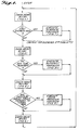
- FIGURES 4-14 are simplified flow diagrams that depict the way the CPU 55 and the PC are programmed to control the flow of data and commands along the card bus 73 and the PC bus 75, respectively.
- the program flow diagrams are simplified in the sense that many obvious operations well understood by computer programmers are not depicted.
- the program flow diagrams have been simplified to emphasize the features of the program that form a portion of the invention and so as to not obfuscate these features in a mass of irrelevant detail.
- FIGURE 4 is a flow diagram illustrating the way the CPU 55 is programmed to control the flow of data between the various interface card components connected to the card bus 73.
- the first step in the illustrated program flow diagram is to check the output of each of the ARINC receiver/transmitters 65, 67, 69 and 71 to determine if any new data is available. If new ARINC data is available on one or more of the outputs, the new ARINC data is handled in the manner illustrated in FIGURE 6 and described below. Basically, this involves transferring the new data from the ARINC receiver/transmitter possessing new data to the card primary memory 59. Next the first discrete input is tested to determine if it is high or low.
- a DISCRETE HANDLER subroutine illustrated in FIGURE 7 and described below, is executed. In essence, this involves setting a related flag in the dual port shared memory 61. After the DISCRETE HANDLER subroutine has been executed or if the first discrete input is low, the remaining discrete inputs, denoted the 2nd-nth discretes in FIGURE 4, are tested to determine if they are high or low.
- ARINC receivers are again checked to determine if new data is available by making a pass through the CHECK ARINC RECEIVERS subroutine, illustrated in FIGURE 6 and described below.
- a test is made to determine if an autotest command has been received from the PC. This is accomplished by testing the state of an autotest flag in the dual port shared memory 61 that is set in the manner described above. If a PC autotest command has occurred, the AUTOTEST HANDLER subroutine illustrated in FIGURE 8 and described below is executed. After the AUTOTEST HANDLER subroutine has been executed, or if no autotest corn mand from the PC has occurred, the ARINC receivers are again checked for new data by making a pass through the CHECK ARINC RECEIVERS subroutine illustrated in FIGURE 6 and described below.
- the program illustrated in FIGURE 4 transfers data from the ARINC receiver/transmitters first to the card program memory and then to the dual port shared memory.
- the reason for this indirect, rather than direct, transfer to a dual port shared memory 61 is due to the fact that dual port shared memories have relatively slow access times when compared to other volatile RAM base memories.
- data is first rapidly transferred from the ARINC receiver/transmitter outputs to the card program memory 59. Thereafter, when more time is available, data is transferred from the card primary memory 59 to the dual port shared memory 61.
- the CPU program (FIGURE 4) also tests the discrete inputs and sets flags in the dual port shared memory 61 for each discrete input that is high.
- discrete inputs provide a second source of commands similar to some of the commands created by actuating PC keyboard function keys (or combinations of keys).
- the presently preferred embodiment of the invention is designed to be a piece of test equipment that is temporarily connected to the data buses of an aircraft rather than being permanently connected.
- the inputs of the ARINC receiver/transmitters of the interface card 53 are connected to the required buses in the electronics bay of an aircraft to be tested.
- the technician using the PC is positioned so that he/she can view the PC monitor 50, which displays information identical to that being displayed on both of the MCDUs 23 and 25 of the aircraft. Simultaneously another observer, either one of the pilots, or a flight test engineer, located in the cockpit of the aircraft, observes the actual MCDU displays.
- the high/low state of the discrete inputs 41 are controlled by the open/closed state of switches operated by the pilot or the flight test engineer. When one of the switches is actuated, a related discrete line goes high. As will be better understood from the previous description, the high causes a flag in the shared memory 61 to be set.
- the set flag is read by the PC program, which then takes whatever action the flag dictates, such as creating a hard copy print or transferring to a more permanent memory location data temporarily stored in a work buffer.
- the discrete inputs allow a flight deck observer, such as a pilot or flight test engineer, to cause selected data to be either printed out and/or transferred to a more permanent storage location by simply actuating one or more switches depending upon the nature of the anomaly.
- a flight deck observer such as a pilot or flight test engineer
- a similar result can be achieved by the pilot pushing a selected MCDU key or combination of keys.
- the interface card program illustrated in FIGURE 4 provides a means for transferring PC commands from the dual port shared memory 61 to either one or more of the discrete outputs, or to the ARINC receiver/transmitters. As noted above, such actions are only allowed to occur when the autotest/monitoring mode of operation has been enabled.
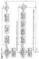
- FIGURE 5 is a flow diagram illustrating the main steps of the data transfer portion of the PC program.
- the first step in the illustrated portion of the PC program is a test that checks the shared memory 61 to see if it has received new data. This test is accomplished by making a pass through the CHECK SHARED MEMORY FOR NEW DATA subroutine illustrated in FIGURE 10 and described below. In general, if new data is present in the shared memory 61, it is transferred to a PC work buffer. After the CHECK SHARED MEMORY FOR NEW DATA subroutine is finished, a test is made to determine if the first discrete bit in the shared memory is high. If the first discrete bit is high, a DISCRETE HANDLER subroutine illustrated in FIGURE 11 and described below is executed.
- this subroutine retrieves data from the PC work buffer and causes the data to be printed in hard copy form as well as stored in a more permanent memory location. After these actions are accomplished, the discrete bit is reset. After the DISCRETE HANDLER subroutine has been executed, or if the first discrete bit is low, the remaining discrete bits, designated the 2nd-nth discrete bits, are tested and the DISCRETE HANDLER subroutine executed as required. As will be recalled, the state of the discrete bits is determined by the high/low state of the discrete inputs.
- the shared memory is again tested to determine if any new data is available for transfer to the PC work buffer by making a pass through the CHECK SHARED MEMORY FOR NEW DATA subroutine illustrated in FIGURE 10 described below. Then, a test of the PC keyboard 52 is made to determine if the user has made an information request by depressing a function key or set of keys. If an information request has been made, a PC INFORMATION REQUEST HANDLER subroutine, illustrated in FIGURE 12 and described below, is executed.
- the shared memory is again checked to determine if new data is available for transfer to the work buffer by making a pass through the CHECK SHARED MEMORY FOR NEW DATA subroutine illustrated in FIGURE 10.
- a test is made to determine if a begin autotest mode of operation request has been made by the user actuating a keyboard function key or set of keys. If the user has requested that the autotest mode of operation begin, the AUTOTEST HANDLER subroutine illustrated in FIGURE 13 and described below is executed.
- the shared memory is again checked for new data by making a pass through the CHECK SHARED MEMORY FOR NEW DATA subroutine illustrated in FIGURE 10. Thereafter, the current left and right MCDU page data stored in the work buffer is displayed (or refreshed) on the monitor 50 of the PC 51. Thereafter, the shared memory 61 is again checked for new data by making a pass through the CHECK SHARED MEMORY FOR NEW DATA subroutine illustrated in FIGURE 10. Thereafter, the program recycles to the beginning.
- the data and instruction handling portion of the PC program continuously checks the output of the shared memory for new data and transfers that data to the work buffer of the PC. Less frequently, the discrete flags of the shared memory 61, set by the card program based on the high/low state of the discrete inputs 41, are tested and, if high, a subroutine that transfers data from the work buffer of the CPU to a printer and a more permanent storage location is executed. Also at less frequent intervals, the PC keyboard is checked for information requests, i.e., user commands.
- the PC INFORMATION REQUEST HANDLER subroutine (FIGURE 12) that responds to keyboard information requests in many respects is similar to the DISCRETE HANDLER subroutine (FIGURE 11). Also, the data transfer portion of the PC program tests the keyboard to determine if the user has commanded the general purpose avionics display monitor to begin an autotest mode of operation. If so, an AUTOTEST HANDLER subroutine is executed. Finally, the PC monitor display is updated or refreshed.
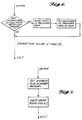
- FIGURE 6 is a subroutine that has passed through each time the ARINC receivers are checked (FIGURE 4).
- the first step in the check ARINC receiver subroutine is to determine if any incoming data is on the output of the ARINC receiver connected to the first receiver channel--the right key push channel of the first ARINC receiver/transmitter 65 illustrated in FIGURE 3. If data is being received, the data is stored to the card program memory 59. Thereafter, a related data present flag in the card program memory is set high. This data flag is later detected by the CPU when a test is made to determine if any data is available to be moved from the primary memory to the shared memory.
- each receiver channel is tested to determine if ARINC data is present. If ARINC data is present, the data is stored in the card primary memory 59 and a related data present flag set.
- FIGURE 7 is a flow diagram of a DISCRETE HANDLER subroutine suitable for use in the card program illustrated in FIGURE 4 and described above, which is executed when a discrete input is high.
- the first step of the data handler subroutine is to set a related discrete flag in the shared memory Thereafter a pass is made through the CHECK ARINC RECEIVERS subroutine illustrated in FIGURE 6 and described above. Then the program exits the DISCRETE HANDLER subroutine.
- FIGURE 8 is a flow diagram of an AUTOTEST HANDLER subroutine suitable for use in the card program illustrated in FIGURE 4 and described above.
- the first step in the AUTOTEST HANDLER subroutine is to set the discrete outputs to the autotest mode relay switches to high. As shown in FIGURE 2 and described above, this results in the right and left MCDUs 23 and 25 being disconnected from the right and left key push data buses 35 and 37. Then the PC command data word is transferred from the shared memory to the related ARINC transmitter. In the case of the embodiment of the invention illustrated in FIGURE 5, this is either the first ARINC receiver/transmitter 65 or the second ARINC receiver/transmitter 67.
- the PC command flag which denoted the presence of a PC command data word, is set low. Thereafter, the ARINC receivers' outputs are checked for new data by making a pass through the check ARINC receiver subroutine illustrated in FIGURE 6 and described above.
- FIGURE 9 is a flow diagram of a DATA TRANSFER HANDLER subroutine suitable for use in the card program illustrated in FIGURE 4 and described above.
- the first step of the DATA TRANSFER HANDLER subroutine illustrated in FIGURE 9 is to move data from the card primary memory to the shared memory.
- the ARINC receivers are checked to see if they are receiving new data by making a pass through the check ARINC receiver subroutine illustrated in FIGURE 6 and described above.
- the card program memory data flag which was set when the data that was moved to the shared memory was stored in the card program memory, is reset. Thereafter the ARINC receivers are again checked for new data by making another pass through the checked ARINC receiver subroutine illustrated in FIGURE 6 and described above.
- FIGURE 10 is a flow diagram of a CHECK SHARED MEMORY FOR NEW DATA subroutine suitable for use in the PC program illustrated in FIGURE 5 and described above.
- the first step of the CHECK SHARED MEMORY FOR NEW DATA subroutine illustrated in FIGURE 10 is a test to determine if any new page data from the left MCDU is present in the shared memory. This test can be accomplished in various ways. One way is to set a flag when new left MCDU page data is transferred from the card primary memory 59 to the dual port shared memory 61 and performing the test by checking the state of the flag. Another way of performing the test is to compare the left MCDU page data in the dual port shared memory 61 with the left MCDU page data in the PC work buffer.
- the first ARINC word is transferred from the shared memory to the PC work buffer. Then a test is made of the transferred ARINC word to determine if it is the last ARINC word in the shared memory. If it is not the last ARINC word, the loop is repeated. After the last word has been transferred, the data is decoded and stored in a history if a history is kept for the particular data, in this case the left MCDU page data, by making a pass through the DECODE DATA AND STORE IN HISTORY IF KEPT routine illustrated in FIGURE 14 and described below.
- the foregoing sequence of steps is repeated for the right MCDU, the left EFIS, the right EFIS, the EICAD, the left key push and the right key push data. That is, the shared memory is tested to determine if new data from any of these sources is present. If present, the ARINC data words are transferred to the PC work buffer, and decoded and stored in a history buffer, if kept for that particular data source. Preferably history buffers are only kept for left and right MCDU data and for left and right key push data. Thereafter the check program exits the stored memory for new data subroutine.
- the work buffer is formed such that new data is written over old data. Thus, at any point in time the work buffer only stores current data.
- FIGURE 11 is a flow diagram of a DISCRETE HANDLER subroutine suitable for use in the PC program illustrated in FIGURE 5 and described above.
- the first step in the DISCRETE HANDLER subroutine illustrated in FIGURE 11 is to retrieve the first ASCII word from the part of the PC history buffer associated with the discrete bit (flag) that caused a pass through the DISCRETE HANDLER subroutine--the left MCDU, for example. Thereafter, the ASCII word is both printed and stored, i.e., transferred to a more permanent memory location. While both operations are preferred, only one can be performed, if desired. Either the ASCII word can be printed or the ASCII word can be transferred to a more permanent storage location.
- a test is made to determine if the ASCII word is the last ASCII word in the part of the PC history buffer associated with the discrete bit that caused the pass through the DISCRETE HANDLER subroutine. If it is not the last ASCII word, the next ASCII word is retrieved from the PC history buffer and the loop repeated.
- the shared memory is checked for new data by making a pass through the CHECK SHARED MEMORY FOR NEW DATA subroutine illustrated in FIGURE 10 and described above. Thereafter, the discrete bit in the shared memory that created the pass through the DISCRETE HANDLER subroutine is reset. Then the program exits the DISCRETE HANDLER subroutine.
- FIGURE 12 is a flow diagram of a PC information handler subroutine suitable for use in the PC program illustrated in FIGURE 5 and described above.
- the first step in the PC INFORMATION REQUEST HANDLER subroutine is a test to determine if the PC keyboard request is a request to print and store the current left MCDU page data. (Alternative to a request to print and store, the request could be for either function, i.e., print or store.) If the PC keyboard is a request to print and store the current left MCDU page data, the first ASCII word is retrieved from the part of the PC history buffer that stores the left MCDU page data and the word is printed and stored by being sent to a printer and a disk.
- a check of the stored memory is made to determine if new data is present by making a pass through the check stored data subroutine illustrated in FIGURE 10 and described above. Thereafter, a test is made to determine if the end of the part of the PC history buffer that stores the current left MCDU page data has been reached. If the word is not the last word in the related part of the PC history buffer, the loop is repeated, i.e., the next ASCII word from the PC history buffer is retrieved and printed and stored. This loop is repeated until the last word in the part of the PC history buffer that stores the current left MCDU page data has been printed and transferred to a more permanent storage location, i.e., a disk. When this occurs, the program exits the PC INFORMATION REQUEST HANDLER subroutine illustrated in FIGURE 12.
- the shared memory is checked for new data by making a pass through the check shared memory subroutine illustrated in FIGURE 10 and described above. Thereafter, the foregoing sequence of steps is repeated for right MCDU, left EFIS, right EFIS and EICAD data, i.e., the PC keyboard request is analyzed to determine if it relates to right MCDU page data, left EFIS data, right EFIS data or EICAD data. If the PC keyboard refers to any of these sources of data, the ASCII words related to the data source are is retrieved one-by-one from the PC history buffer and printed and stored. When the end of the related part of the history buffer is reached, the program exits the PC INFORMATION REQUEST HANDLER subroutine.
- a test is made to determine if the PC keyboard request is a request to print and store the data in the left MCDU history buffer. If the request is a request to print and store left MCDU history, a check of the shared memory is made to determine if new data is present by making a pass through the check stored memory for new data subroutine illustrated in FIGURE 10 and described above. Thereafter, the first ASCII word in the left MCDU history buffer is retrieved, and printed and stored. (Alternatively the left MCDU history buffer data could be printed or stored.) Storage occurs by transferring the ASCII word to a disk or other more permanent storage medium.
- the PC keyboard request is not a request to print and store left MCDU history, a pass is made through the CHECK SHARED MEMORY FOR NEW DATA subroutine illustrated in FIGURE 10 and described above. Thereafter, the PC keyboard request is tested in sequence to determine if the request is a request to print and store right MCDU, left key push or right key push history data. If so, the sequence of retrieval, printing and storing steps illustrated in FIGURE 12 and described above for the left MCDU history occurs. Following each keyboard request test is a check to determine if new data is present in the shared memory by making a pass through the CHECK SHARED MEMORY FOR NEW DATA subroutine illustrated in FIGURE 10 and described above.
- FIGURE 13 is a flow diagram of an AUTOTEST HANDLER subroutine suitable for use in the PC program illustrated in FIGURE 5 and described above.
- the first step in the AUTOTEST HANDLER subroutine illustrated in FIGURE 3 is the transfer of an autotest file from a permanent storage location, e.g., a disk to an autotest buffer. Thereafter, the first PC corn mand word in the autotest buffer is transferred to the shared memory. Next the autotest flag in the shared memory is set. Then the PC command flag in the shared buffer is set. Thereafter, ter, the program checks to determine if new data is present in the shared memory by making a pass through the CHECK SHARED MEMORY FOR NEW DATA subroutine illustrated in FIGURE 10 and described above.
- a test is made to determine if any more PC commands are in the autotest buffer. If other PC commands are present in the autotest buffer, a test is made to determine if the PC command flag has been reset. If the PC command flag is not reset, because the PC command data has not yet been transferred from the shared memory to the appropriate ARINC receiver/transmitter in the manner described above, the program enters a wait loop. When the PC corn mand flag is reset, the program transfers the next PC command word from the autotest buffer to the shared memory. This loop is repeated until all the PC command words in the autotest buffer have been transferred to the shared memory.
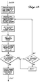
- FIGURE 14 illustrates a DECODE DATA AND STORE IN HISTORY IF KEPT routine suitable for use in the CHECK SHARED MEMORY FOR NEW DATA subroutine illustrated in FIGURE 10 and described above.
- the first step of the DECODE DATA AND STORE IN HISTORY IF KEPT routine illustrated in FIGURE 14 is a test to determine if there is new page data from the left MCDU present in the left MCDU page data section of the PC work buffer. If new page data from the left MCDU is present in the work buffer, the time from a clock that forms part of the PC is stored in a page history buffer. Thereafter the first ARINC word of the new left MCDU page data is retrieved from the PC work buffer.
- the ARINC word is decoded, (i.e., converted) from ARINC format to ASCII format. Thereafter, the ASCII format word is stored in the page history buffer in association with the PC clock time. Then a test is made to determine if the ASCII word is the last word of the left MCDU page data. If the ASCII word is not the last word of the left MCDU page data, the next left MCDU page data ARINC word is retrieved from the PC work buffer and the foregoing steps repeated. This loop is repeated until the MCDU page data word in ARINC format is converted to ASCII format and stored in the left MCDU page history buffer. Then the main loop is repeated for the right MCDU page data.
- the right MCDU page data stored in the PC work buffer is transferred to the right MCDU page history buffer, or if no new right MCDU page data is present in the PC work buffer, a test is made to determine if new left keypad data is present in the PC work buffer. If new left keypad data is present, PC clock time is stored in a left key push history buffer. Thereafter, the new left key push data word in ARINC form is retrieved from the PC work buffer. The retrieved ARINC word is decoded (i.e., converted) from ARINC format to ASCII format and the ASCII format word is stored in the left key push history buffer in association with the PC clock time.
- the invention provides a general purpose avionics display monitor that copies data flowing on the avionics buses of an aircraft to the memory of a PC for either more permanent storage or for printout, as required.
- the use of two independent data transfer loops efficiently and rapidly transfers data.
- the invention allows data associated with display anomalies to be readily stored for easy retrieval and analysis at a later date. Rather than storing huge amounts of data that must be processed prior to analysis, the invention provides a system that only stores relevant data, i.e., the data of interest to the evaluation of an anomaly recognized by an observer.
Landscapes
- Engineering & Computer Science (AREA)
- General Engineering & Computer Science (AREA)
- Physics & Mathematics (AREA)
- General Physics & Mathematics (AREA)
- Theoretical Computer Science (AREA)
- Computer Hardware Design (AREA)
- Quality & Reliability (AREA)
- Automation & Control Theory (AREA)
- Debugging And Monitoring (AREA)
- Audible And Visible Signals (AREA)
Claims (20)
- Universal-Flugführungs-Anzeigemonitor, mit:(a) Interfacemitteln zum Bilden einer Schnittstelle zwischen einem Datenverarbeitungssystem und einer Vielzahl von Flugzeug-Datensammelleitungen zum Fördern von Daten aus den Flugzeug-Datensammelleitungen zum Datenverarbeitungssystem, gekennzeichnet durch:(i) einen Gemeinschaftsspeicher (61) mit zwei Eingängen;(ii) eine Vielzahl von Datenempfängern (65, 67, 69, 71), die zum Anschluß an die Flugzeug-Datensammelleitungen eingerichtet sind, um Daten zu empfangen, die auf den genannten Flugzeug-Datensammelleitungen fließen;(iii) eine Datensammelleitung (73), die an den Gemeinschaftsspeicher (61) mit zwei Eingängen angekoppelt ist, sowie an die genannte Vielzahl von Datenempfängern (65, 67, 69, 71), um hierzwischen Daten zu übertragen; und(iv) eine zentrale Verarbeitungseinheit (55), die an die genannte Datensammelleitung (73) angekoppelt ist, wobei die genannte zentrale Verarbeitungseinheit so programmiert ist, daß sie den Datenstrom auf der genannten Datensammelleitung (73) so steuert, daß Daten, die von der genannten Vielzahl von Datenempfängern empfangen werden, an den genannten Gemeinschaftsspeicher (61) mit zwei Eingängen über einen Zwischenspeicher (59) übertragen werden;(v) eine Vielzahl gesonderter Eingabe- und Ausgabeleitungen (63), die an die genannte Datensammelleitung (73) angekoppelt sind;(vi) einen Zwischenspeicher (59), der an die genannte Datensammelleitung (73) angekoppelt ist, um die genannten Daten zwischenzeitlich zu speichern und die genannten Daten an den genannten Gemeinschaftsspeicher (61) mit zwei Eingängen zu übertragen; und(b) einem Datenverarbeitungssystem (51), das an den genannten Gemeinschaftsspeicher (61) mit zwei Eingängen angekoppelt ist, um Daten zu empfangen, die im genannten Gemeinschaftsspeicher (61) mit zwei Eingängen abgespeichert sind, und um die genannten Daten zu empfangen und abzuspeichern, wobei das genannte Datenverarbeitungssystem die folgenden Merkmale aufweist:(i) einen Benutzer-Schnittstellenmechanismus (53) zum Empfang von Benutzeranweisungen;(ii) einen Massenspeicher (43) zum Empfangen von Daten aus dem genannten Gemeinschaftsspeicher (61) mit zwei Eingängen und zum Abspeichern der genannten Daten, wenn ein Benutzer eine erste, vorbestimmte Anweisung benutzt, die vom genannten Benutzer-Schnittstellenmechanismus zu erzeugen ist; und(iii) einen Monitor zum Anzeigen der Daten, die in einem Arbeits-Pufferspeicher abgespeichert sind.
- Universal-Flugführungs-Anzeigemonitor, wie beansprucht in Anspruch 1, worin die genannten Schnittstellenmittel einen Programmspeicher (59) umfassen, der mit der genannten Datensammelleitung gekoppelt ist, und worin die genannten Daten, die von der genannten Vielzahl von Datenempfängern empfangen werden, zuerst rasch an den genannten Programmspeicher (59) übertragen und später langsamer an den genannten Gemeinschaftsspeicher (61) mit zwei Eingängen übertragen werden.
- Universal-Flugführungs-Anzeigemonitor, wie beansprucht in Anspruch 1 oder 2, worin das genannte Datenverarbeitungssystem einen Arbeits-Pufferspeicher zum zeitweisen Abspeichern von Daten umfaßt, die vom genannten Gemeinschaftsspeicher (61) mit zwei Eingängen empfangen werden, bevor die genannten Daten im genannten Massenspeicher (43) empfangen und abgespeichert werden, wenn ein Benutzer veranlaßt, daß eine vorbestimmte Anweisung vom genannten Benutzer-Schnittstellenmechanismus erzeugt wird.
- Universal-Flugführungs-Anzeigemonitor, wie beansprucht in Anspruch 1, worin das genannte Datenverarbeitungssystem auch einen Drucker umfaßt, um Daten auszudrucken, die zeitweise im genannten Arbeits-Pufferspeicher abgespeichert sind, wenn ein Benutzer veranlaßt, daß eine zweite, vorbestimmte Anweisung vom genannten Benutzer-Schnittstellenmechanismus erzeugt wird.
- Universal-Flugführungs-Anzeigemonitor, wie beansprucht in Anspruch 4, worin die genannten Schnittstellenmittel einen Programmspeicher (59) umfassen, der an die genannte Datensammelleitung (73) angekoppelt ist, und worin die genannten Daten, die durch die genannte Vielzahl von Datenempfängern empfangen werden, zuerst rasch an den genannten Programmspeicher (59) übertragen und später langsamer an den genannten Gemeinschaftsspeicher (61) mit zwei Eingängen übertragen werden.
- Universal-Flugführungs-Anzeigemonitor, wie beansprucht in Anspruch 4 oder 5, worin das genannte Datenverarbeitungssystem einen Arbeits-Pufferspeicher zum zeitweisen Abspeichern von Daten umfaßt, die aus dem Gemeinschaftsspeicher (61) mit zwei Eingängen empfangen werden, bevor die genannten Daten im genannten Massenspeicher (43) empfangen und abgespeichert werden, wenn ein Benutzer es veranlaßt, daß eine vorbestimmte Anweisung vom Benutzer-Schnittstellenmechanismus (53) erzeugt wird.
- Universal-Flugführungs-Anzeigemonitor, wie beansprucht in Anspruch 4, worin die genannte erste und zweite, vorbestimmte Anweisung dieselben sind.
- Universal-Flugführungs-Anzeigemonitor, wie beansprucht in Anspruch 7, worin die genannten Schnittstellenmittel einen Programmspeicher (59) umfassen, der mit der genannten Datensammelleitung (73) gekoppelt ist, und worin die genannten Daten, die von der genannten Vielzahl von Datenempfängern empfangen werden, zuerst rasch auf den genannten Programmspeicher (59) übertragen und später langsamer auf den genannten Gemeinschaftsspeicher (61) mit zwei Eingängen übertragen werden.
- Universal-Flugführungs-Anzeigemonitor, wie beansprucht in Anspruch 7 oder 8, worin das genannte Datenverarbeitungssystem einen Arbeits-Pufferspeicher zum zeitweisen Abspeichern von Daten aufweist, die vom genannten Gemeinschaftsspeicher (61) mit zwei Eingängen empfangen werden, bevor die genannten Daten im genannten Massenspeicher empfangen und abgespeichert werden, wenn ein Benutzer es veranlaßt, daß eine vorbestimmte Anweisung vom Benutzer-Schnittstellenmechanismus (53) erzeugt wird.
- Universal-Flugführungs-Anzeigemonitor, wie beansprucht in Anspruch 1, worin:(a) der genannte Universal-Flugführungs-Anzeigemonitor eine Quelle gesonderter Eingaben umfaßt;(b) die genannte Datensammelleitung (73) der genannten Schnittstellenmittel mit der genannten Quelle gesonderter Eingaben gekoppelt ist; und(c) der genannte Gemeinschaftsspeicher (61) mit zwei Eingängen einen Datenmerkerabschnitt umfaßt, und worin die genannte programmierte, zentrale Verarbeitungseinheit den Zustand der genannten Datenmerker des genannten Gemeinschaftsspeichers mit zwei Eingängen auf der Grundlage des H/L-Zustands der genannten gesonderten Eingaben steuert.
- Universal-Flugführungs-Anzeigemonitor, wie beansprucht in Anspruch 7, worin die genannten Flugzeug-Sammelleitungen mindestens eine Mehrzweck-Steueranzeigeeinheit (MCDU) mit einem Flug-Mananagementrechner (FMC) verbinden, um Seitenanzeigedaten vom genannten Flug-Managementrechner an die genannte Mehrzweck-Steueranzeigeeinheit sowie Knopfdruckdaten von der genannten Mehrzweck-Steueranzeigeeinheit an den genannten Flug-Managementrechner zu übertragen.
- Universal-Flugführungs-Anzeigemonitor, wie beansprucht in Anspruch 11, worin die genannten Schnittstellenmittel einen Programmspeicher (59) aufweisen, der an die genannte Datensammelleitung (73) angekoppelt ist, und worin die genannten Daten, die von der genannten Vielzahl von Datenempfängern empfangen werden, zuerst rasch auf den genannten Programmspeicher übertragen und später langsamer auf den genannten Gemeinschaftsspeicher (61) mit zwei Eingängen übertragen werden.
- Universal-Flugführungs-Anzeigemonitor, wie beansprucht in Anspruch 11 oder 12, worin das genannte Datenverarbeitungssystem einen Arbeits-Pufferspeicher zum zeitweisen Abspeichern von Daten umfaßt, die vom genannten Gemeinschaftsspeicher (61) mit zwei Eingängen empfangen werden, bevor die genannten Daten im genannten Massenspeicher empfangen und abgespeichert werden, wenn es ein Benutzer veranlaßt, daß eine vorbestimmte Anweisung vom Benutzer-Schnittstellenmechanismus erzeugt wird.
- Universal-Flugführungs-Anzeigemonitor, wie beansprucht in Anspruch 11, worin das genannte Datenverarbeitungssystem auch einen Drucker aufweist, um Daten, die zeitweise im genannten Arbeits-Pufferspeicher abgespeichert sind, auszudrucken, wenn es ein Benutzer veranlaßt, daß eine zweite, vorbestimmte Anweisung vom genannten Benutzer-Schnittstellenmechanismus (53) erzeugt wird.
- Universal-Flugführungs-Anzeigemonitor, wie beansprucht in Anspruch 14, worin die genannten Schnittstellenmittel einen Programmspeicher (59) umfassen, der an die genannte Datensammelleitung (73) angekoppelt ist, und worin die genannten Daten, die von der genannten Vielzahl von Datenempfängern empfangen werden, zuerst rasch an den Programmspeicher übertragen und später langsamer an den Gemeinschaftsspeicher (61) mit zwei Eingängen übertragen werden.
- Universal-Flugführungs-Anzeigemonitor, wie beansprucht in Anspruch 14 oder 15, worin das genannte Datenverarbeitungssystem einen Arbeits-Pufferspeicher zum zeitweisen Abspeichern von Daten umfaßt, die vom Gemeinschaftsspeicher (61) mit zwei Eingängen empfangen sind, bevor die genannten Daten im genannten Massenspeicher (43) empfangen und abgespeichert werden, wenn es ein Benutzer veranlaßt, daß eine vorbestimmte Anweisung vom Benutzer-Schnittstellenmechanismus erzeugt wird.
- Universal-Flugführungs-Anzeigemonitor, wie beansprucht in Anspruch 14, worin die genannte erste und zweite, vorbestimmte Anweisung dieselben sind.
- Universal-Flugführungs-Anzeigemonitor, wie beansprucht in Anspruch 17, worin die genannten Schnittstellenmittel einen Programmspeicher (59) umfassen, der mit der genannten Datensammelleitung (73) gekoppelt ist, und worin die genannten Daten, die von der genannten Vielzahl von Datenempfängern empfangen werden, zuerst rasch zum genannten Programmspeicher übertragen und später langsamer zum genannten Gemeinschaftsspeicher (61) mit zwei Eingängen übertragen werden.
- Universal-Flugführungs-Anzeigemonitor, wie beansprucht in Anspruch 17 oder 18, worin das genannte Datenverarbeitungssystem einen Arbeits-Pufferspeicher zum zeitweisen Abspeichern von Daten umfaßt, die vom Gemeinschaftsspeicher (61) mit zwei Eingängen empfangen werden, bevor die genannten Daten im Massenspeicher (43) empfangen und abgespeichert werden, wenn es ein Benutzer veranlaßt, daß eine vorbestimmte Anweisung vom Benutzer-Schnittstellenmechanismus erzeugt wird.
- Universal-Flugführungs-Anzeigemonitor, wie beansprucht in Anspruch 11, worin:(a) der genannte Universal-Flugführungs-Anzeigemonitor mindestens einen ARINC-Sender aufweist, der mit der Datensammelleitung gekoppelt ist, die Knopfdruckdaten von der genannten Mehrzweck-Steueranzeigeeinheit zum genannten Flug-Managementrechner überträgt;(b) der genannte Universal-Flugführungs-Anzeigemonitor Mittel aufweist, um die genannte Mehrzweck-Steueranzeigeeinheit von der Datensammelleitung abzukoppeln, die die Knopfdruckdaten von der Mehrzweck-Steueranzeigeeinheit zum Flug-Managementrechner überträgt;(c) das genannte Datenverarbeitungssystem Knopfdruckdaten ähnlich zu denen erzeugt, die von der genannten Mehrzweck-Steueranzeigeeinheit erzeugt werden, wenn es ein Benutzer veranlaßt, daß vorbestimmte Selbsttestanweisungen vom genannten Benutzer-Schnittstellenmechanismus erzeugt werden;(d) die Benutzer-Knopfdruckdaten, die vom genannten Datenverarbeitungssystem erzeugt werden, an den GemeinschaftsSpeicher mit zwei Eingängen übertragen werden; und(e) das genannte Programm der zentralen Verarbeitungseinheit die genannten Knopfdruckdaten vom Gemeinschaftsspeicher mit zwei Eingängen zu dem mindestens einen ARINC-Sender überträgt.
Applications Claiming Priority (2)
| Application Number | Priority Date | Filing Date | Title |
|---|---|---|---|
| US07/380,130 US5019980A (en) | 1989-07-14 | 1989-07-14 | General purpose avionics display monitor |
| US380130 | 1989-07-14 |
Publications (3)
| Publication Number | Publication Date |
|---|---|
| EP0408094A2 EP0408094A2 (de) | 1991-01-16 |
| EP0408094A3 EP0408094A3 (en) | 1992-05-13 |
| EP0408094B1 true EP0408094B1 (de) | 1997-07-09 |
Family
ID=23500011
Family Applications (1)
| Application Number | Title | Priority Date | Filing Date |
|---|---|---|---|
| EP90201292A Expired - Lifetime EP0408094B1 (de) | 1989-07-14 | 1990-05-21 | Anzeigemonitor für Allzweckavionik |
Country Status (3)
| Country | Link |
|---|---|
| US (1) | US5019980A (de) |
| EP (1) | EP0408094B1 (de) |
| DE (1) | DE69031012T2 (de) |
Cited By (1)
| Publication number | Priority date | Publication date | Assignee | Title |
|---|---|---|---|---|
| US7774112B2 (en) | 2004-09-27 | 2010-08-10 | Teledyne Technologies Incorporated | System and method for flight data recording |
Families Citing this family (32)
| Publication number | Priority date | Publication date | Assignee | Title |
|---|---|---|---|---|
| US5239468A (en) * | 1990-12-07 | 1993-08-24 | United Technologies Corporation | Automated helicopter maintenance monitoring |
| US5226124A (en) * | 1991-06-05 | 1993-07-06 | Ambrosia Microcomputer Products, Inc. | Communication interface between a radio control transmitter and a computer data bus |
| US5454074A (en) * | 1991-09-18 | 1995-09-26 | The Boeing Company | Electronic checklist system |
| US5377109A (en) * | 1992-07-31 | 1994-12-27 | Lear Astronics Corp. | Failsafe digital bus to analog protocol converter system |
| US5424949A (en) * | 1993-07-30 | 1995-06-13 | Honeywell Inc. | Multi-channel data receiver system |
| US5522026A (en) * | 1994-03-18 | 1996-05-28 | The Boeing Company | System for creating a single electronic checklist in response to multiple faults |
| US6151567A (en) * | 1994-05-27 | 2000-11-21 | Hamilton Sundstrand Corporation | Data communication analysis and simulation tool |
| US5896292A (en) * | 1995-06-05 | 1999-04-20 | Canon Kabushiki Kaisha | Automated system for production facility |
| US5706215A (en) * | 1995-06-30 | 1998-01-06 | Harris Corporation | Method and system for adjusting replacement component characteristics |
| GB2308902B (en) * | 1996-01-04 | 2000-03-29 | Motorola Inc | Peripheral module and microprocessor system |
| FR2743966B1 (fr) * | 1996-01-19 | 1998-02-20 | Sextant Avionique | Procede de gestion temporelle d'un bus multiplexe |
| US6112140A (en) * | 1996-05-14 | 2000-08-29 | The Boeing Company | Flight management system providing for automatic control display unit backup utilizing structured data routing |
| US6115656A (en) * | 1997-06-17 | 2000-09-05 | Mcdonnell Douglas Corporation | Fault recording and reporting method |
| FR2778765B1 (fr) * | 1998-05-18 | 2001-10-05 | Eurocopter France | Systeme de surveillance du fonctionnement d'un aeronef, notamment d'un helicoptere |
| US6314343B1 (en) * | 1999-12-23 | 2001-11-06 | Sikorsky Aircraft Corp. | Aircraft flight mode selector system |
| US6604030B1 (en) * | 2000-06-06 | 2003-08-05 | Ozuna Holdings Incorporated | Single fault impervious integrated control and monitoring system |
| US20030033332A1 (en) * | 2001-07-18 | 2003-02-13 | Lindsley Steven E. | Control/display unit page builder software tool |
| US6832138B1 (en) | 2002-02-28 | 2004-12-14 | Garmin International, Inc. | Cockpit instrument panel systems and methods with redundant flight data display |
| US6985801B1 (en) | 2002-02-28 | 2006-01-10 | Garmin International, Inc. | Cockpit instrument panel systems and methods with redundant flight data display |
| US6816728B2 (en) * | 2002-04-24 | 2004-11-09 | Teledyne Technologies Incorporated | Aircraft data communication system and method |
| US7149612B2 (en) * | 2004-01-05 | 2006-12-12 | Arinc Incorporated | System and method for monitoring and reporting aircraft quick access recorder data |
| US7489992B2 (en) * | 2004-04-12 | 2009-02-10 | Sagem Avionics, Inc. | Method and system for remotely communicating and interfacing with aircraft condition monitoring systems |
| FR2876814B1 (fr) * | 2004-10-14 | 2006-12-15 | Renault Sas | Systeme d'enregistrement d'un contexte d'incident dans un vehicule automobile |
| US7711455B1 (en) * | 2006-08-09 | 2010-05-04 | The United States Of America As Represented By The Administrator Of The National Aeronautics And Space Administration | Propulsion controlled aircraft computer |
| US7684904B2 (en) * | 2007-06-27 | 2010-03-23 | Arinc Incorporated | Systems and methods for communication, navigation, surveillance and sensor system integration in a vehicle |
| US20090199205A1 (en) * | 2008-02-06 | 2009-08-06 | Honeywell International Inc. | Configurable graphics virtual machine based display system |
| US9830564B2 (en) | 2011-11-30 | 2017-11-28 | The Boeing Company | Customized automated checklist creation, execution and communication |
| KR101666398B1 (ko) * | 2012-10-30 | 2016-10-17 | 한국전자통신연구원 | Arinc 653 기반 운영체제에서의 모니터링 방법 및 장치 |
| US20160332750A1 (en) * | 2015-01-12 | 2016-11-17 | Hamilton Sundstrand Corporation | Aircraft active history memory module |
| US9699200B2 (en) * | 2015-05-07 | 2017-07-04 | The Boeing Company | Inline arinc data authenticity inspection module, method and computer program product |
| JP6212073B2 (ja) | 2015-06-29 | 2017-10-11 | ファナック株式会社 | プログラムの内容に応じて格納先を自動選択する機能を備えた数値制御装置 |
| CN116192716B (zh) * | 2023-02-28 | 2024-05-17 | 华东师范大学 | 一种基于zynq的航电多协议总线测试平台 |
Family Cites Families (15)
| Publication number | Priority date | Publication date | Assignee | Title |
|---|---|---|---|---|
| US3603948A (en) * | 1968-11-22 | 1971-09-07 | Bendix Corp | Fault identification, isolation and display for use with an aircraft control system |
| US3928830A (en) * | 1974-09-19 | 1975-12-23 | Ibm | Diagnostic system for field replaceable units |
| US4249186A (en) * | 1977-08-24 | 1981-02-03 | Leeds & Northrup Limited | Processor system for display and/or recording of information |
| DE2824190A1 (de) * | 1978-06-02 | 1979-12-06 | Bosch Gmbh Robert | Mikrorechner-system zur steuerung von betriebsvorgaengen in kraftfahrzeugen, mit einer diagnoseeinrichtung zur ueberpruefung des kraftfahrzeuges |
| EP0072000B1 (de) * | 1981-08-07 | 1988-10-19 | Nippondenso Co., Ltd. | System zur Fehlererkennung und -anzeige für Motorfahrzeuge |
| US4787053A (en) * | 1981-12-30 | 1988-11-22 | Semco Instruments, Inc. | Comprehensive engine monitor and recorder |
| DE3374723D1 (en) * | 1982-02-17 | 1988-01-07 | British Aerospace | Aircraft data instrumentation and acquisition system |
| US4483002A (en) * | 1982-04-19 | 1984-11-13 | International Business Machines Corporation | Digital device testing apparatus and method |
| DE3302929A1 (de) * | 1983-01-28 | 1984-08-02 | Siemens AG, 1000 Berlin und 8000 München | Speicherprogrammierbare steuerung |
| US4621335A (en) * | 1983-05-31 | 1986-11-04 | Allied Corporation | Real time recall feature for an engine data processor system |
| EP0164341B1 (de) * | 1983-11-17 | 1989-10-18 | The Boeing Company | Automatishes fehlerberichtssystem |
| US4672611A (en) * | 1984-04-20 | 1987-06-09 | Fuji Electric Company Ltd. | Serial transmission line monitoring device |
| US4651298A (en) * | 1984-05-30 | 1987-03-17 | The United States Of America As Represented By The Secretary Of The Air Force | Selection of data from busses for test |
| US4845495A (en) * | 1988-02-17 | 1989-07-04 | Allied-Signal Inc. | Integrated avionics control and display arrangement |
| US4943919A (en) * | 1988-10-17 | 1990-07-24 | The Boeing Company | Central maintenance computer system and fault data handling method |
-
1989
- 1989-07-14 US US07/380,130 patent/US5019980A/en not_active Expired - Lifetime
-
1990
- 1990-05-21 DE DE69031012T patent/DE69031012T2/de not_active Expired - Fee Related
- 1990-05-21 EP EP90201292A patent/EP0408094B1/de not_active Expired - Lifetime
Cited By (2)
| Publication number | Priority date | Publication date | Assignee | Title |
|---|---|---|---|---|
| US7774112B2 (en) | 2004-09-27 | 2010-08-10 | Teledyne Technologies Incorporated | System and method for flight data recording |
| US7945360B2 (en) | 2004-09-27 | 2011-05-17 | Teledyne Technologies Incorporated | Cost reduction system and method for flight data recording |
Also Published As
| Publication number | Publication date |
|---|---|
| US5019980A (en) | 1991-05-28 |
| DE69031012D1 (de) | 1997-08-14 |
| EP0408094A2 (de) | 1991-01-16 |
| DE69031012T2 (de) | 1997-10-30 |
| EP0408094A3 (en) | 1992-05-13 |
Similar Documents
| Publication | Publication Date | Title |
|---|---|---|
| US5019980A (en) | General purpose avionics display monitor | |
| US4943919A (en) | Central maintenance computer system and fault data handling method | |
| US6077077A (en) | Architecture and process for simulating the data transmitted to a navigation management computer | |
| US6789007B2 (en) | Integrated onboard maintenance documentation with a central maintenance system | |
| EP0085437A2 (de) | Überwachung für Datenübertragungsleitung | |
| US6397128B1 (en) | Flight data recorder system | |
| US5969668A (en) | Integration of aime augmentation into GNSS products | |
| US7869385B2 (en) | Interactivity with a bus interface card | |
| Ananda | General aviation aircraft avionics: Integration & system tests | |
| Palmer et al. | A high-performance simulated on-board avionics architecture to support traffic operations research | |
| US5600786A (en) | FIFO fail-safe bus | |
| KR102698820B1 (ko) | 시험 장치 및 시험 방법 | |
| Rzucidło | Monitoring and data acquisition system for experimental general aviation fly‐by‐wire aircraft | |
| US7523368B2 (en) | Diagnostics unit using boundary scan techniques for vehicles | |
| Shi et al. | Remote-controlled air data test system in Iron-Bird | |
| Raymond et al. | Digital Computation Makes AFCS More Reliable | |
| Byrne et al. | Launch processing system | |
| Grimm et al. | An Avionics Diagnostics System for Regional Airlines and Business Aircraft Applied in the Beech Starship I | |
| Ross | A methodology for system engineering a medium scale system and its application to the geophysical airborne survey system | |
| Emfinger | ACT System Design for Reliability, Maintainability and Redundancy Management | |
| DERBYSHIRE et al. | B-1 Central Integrated Test System/CITS | |
| Rauch | Telemetry Systems of the Future | |
| Manders | ROLM computers in the flight testing of the Fokker F29 aircraft | |
| Kelly et al. | Description of the VTOL Approach and Landing Technology (VALT) CH-47 research system | |
| Denney et al. | Integrated Testing and Maintenance Technologies. |
Legal Events
| Date | Code | Title | Description |
|---|---|---|---|
| PUAI | Public reference made under article 153(3) epc to a published international application that has entered the european phase |
Free format text: ORIGINAL CODE: 0009012 |
|
| AK | Designated contracting states |
Kind code of ref document: A2 Designated state(s): DE FR GB IT NL |
|
| PUAL | Search report despatched |
Free format text: ORIGINAL CODE: 0009013 |
|
| AK | Designated contracting states |
Kind code of ref document: A3 Designated state(s): DE FR GB IT NL |
|
| 17P | Request for examination filed |
Effective date: 19921109 |
|
| 17Q | First examination report despatched |
Effective date: 19960126 |
|
| GRAG | Despatch of communication of intention to grant |
Free format text: ORIGINAL CODE: EPIDOS AGRA |
|
| GRAH | Despatch of communication of intention to grant a patent |
Free format text: ORIGINAL CODE: EPIDOS IGRA |
|
| GRAH | Despatch of communication of intention to grant a patent |
Free format text: ORIGINAL CODE: EPIDOS IGRA |
|
| GRAA | (expected) grant |
Free format text: ORIGINAL CODE: 0009210 |
|
| AK | Designated contracting states |
Kind code of ref document: B1 Designated state(s): DE FR GB IT NL |
|
| REF | Corresponds to: |
Ref document number: 69031012 Country of ref document: DE Date of ref document: 19970814 |
|
| ET | Fr: translation filed | ||
| PLBE | No opposition filed within time limit |
Free format text: ORIGINAL CODE: 0009261 |
|
| STAA | Information on the status of an ep patent application or granted ep patent |
Free format text: STATUS: NO OPPOSITION FILED WITHIN TIME LIMIT |
|
| 26N | No opposition filed | ||
| REG | Reference to a national code |
Ref country code: GB Ref legal event code: IF02 |
|
| PGFP | Annual fee paid to national office [announced via postgrant information from national office to epo] |
Ref country code: DE Payment date: 20030626 Year of fee payment: 14 |
|
| PGFP | Annual fee paid to national office [announced via postgrant information from national office to epo] |
Ref country code: NL Payment date: 20040429 Year of fee payment: 15 |
|
| PGFP | Annual fee paid to national office [announced via postgrant information from national office to epo] |
Ref country code: GB Payment date: 20040512 Year of fee payment: 15 |
|
| PGFP | Annual fee paid to national office [announced via postgrant information from national office to epo] |
Ref country code: FR Payment date: 20040519 Year of fee payment: 15 |
|
| PG25 | Lapsed in a contracting state [announced via postgrant information from national office to epo] |
Ref country code: DE Free format text: LAPSE BECAUSE OF NON-PAYMENT OF DUE FEES Effective date: 20041201 |
|
| PG25 | Lapsed in a contracting state [announced via postgrant information from national office to epo] |
Ref country code: IT Free format text: LAPSE BECAUSE OF NON-PAYMENT OF DUE FEES;WARNING: LAPSES OF ITALIAN PATENTS WITH EFFECTIVE DATE BEFORE 2007 MAY HAVE OCCURRED AT ANY TIME BEFORE 2007. THE CORRECT EFFECTIVE DATE MAY BE DIFFERENT FROM THE ONE RECORDED. Effective date: 20050521 Ref country code: GB Free format text: LAPSE BECAUSE OF NON-PAYMENT OF DUE FEES Effective date: 20050521 |
|
| PG25 | Lapsed in a contracting state [announced via postgrant information from national office to epo] |
Ref country code: NL Free format text: LAPSE BECAUSE OF NON-PAYMENT OF DUE FEES Effective date: 20051201 |
|
| GBPC | Gb: european patent ceased through non-payment of renewal fee |
Effective date: 20050521 |
|
| PG25 | Lapsed in a contracting state [announced via postgrant information from national office to epo] |
Ref country code: FR Free format text: LAPSE BECAUSE OF NON-PAYMENT OF DUE FEES Effective date: 20060131 |
|
| NLV4 | Nl: lapsed or anulled due to non-payment of the annual fee |
Effective date: 20051201 |
|
| REG | Reference to a national code |
Ref country code: FR Ref legal event code: ST Effective date: 20060131 |