EP0407793A2 - Friction damper - Google Patents
Friction damper Download PDFInfo
- Publication number
- EP0407793A2 EP0407793A2 EP90111953A EP90111953A EP0407793A2 EP 0407793 A2 EP0407793 A2 EP 0407793A2 EP 90111953 A EP90111953 A EP 90111953A EP 90111953 A EP90111953 A EP 90111953A EP 0407793 A2 EP0407793 A2 EP 0407793A2
- Authority
- EP
- European Patent Office
- Prior art keywords
- friction
- damper according
- housing
- friction damper
- grease
- Prior art date
- Legal status (The legal status is an assumption and is not a legal conclusion. Google has not performed a legal analysis and makes no representation as to the accuracy of the status listed.)
- Granted
Links
Images
Classifications
-
- F—MECHANICAL ENGINEERING; LIGHTING; HEATING; WEAPONS; BLASTING
- F16—ENGINEERING ELEMENTS AND UNITS; GENERAL MEASURES FOR PRODUCING AND MAINTAINING EFFECTIVE FUNCTIONING OF MACHINES OR INSTALLATIONS; THERMAL INSULATION IN GENERAL
- F16F—SPRINGS; SHOCK-ABSORBERS; MEANS FOR DAMPING VIBRATION
- F16F7/00—Vibration-dampers; Shock-absorbers
- F16F7/08—Vibration-dampers; Shock-absorbers with friction surfaces rectilinearly movable along each other
- F16F7/09—Vibration-dampers; Shock-absorbers with friction surfaces rectilinearly movable along each other in dampers of the cylinder-and-piston type
-
- D—TEXTILES; PAPER
- D06—TREATMENT OF TEXTILES OR THE LIKE; LAUNDERING; FLEXIBLE MATERIALS NOT OTHERWISE PROVIDED FOR
- D06F—LAUNDERING, DRYING, IRONING, PRESSING OR FOLDING TEXTILE ARTICLES
- D06F37/00—Details specific to washing machines covered by groups D06F21/00 - D06F25/00
- D06F37/20—Mountings, e.g. resilient mountings, for the rotary receptacle, motor, tub or casing; Preventing or damping vibrations
Definitions
- the invention relates to a friction damper, in particular for washing machines with a spin cycle, consisting of an essentially circular-cylindrical housing and a plunger which can be moved coaxially therein, with one end leading out of the housing and at the other end provided with an approximately cylindrical friction piston, the friction piston having at least one approximately circular-cylindrical support section and this radially projecting and axially unchangeable limiting counter-flanges, wherein on the support section and between the counter-flanges a friction surface made of elastically resilient material pressed against the inner wall of the housing is arranged, and a lubricating grease storage chamber on the friction piston is trained.
- friction dampers are known from DE-OS 36 04 286 (corresponds to U.S. patent 4,729,458). These lubricated friction dampers have proven themselves to a great extent in practice; in particular, they are used extensively in washing machines.
- the friction linings usually consist of cellular, foamed plastic, the cells of the plastic being impregnated with fat. It has been shown that under extreme loads, the friction changes from a lubricated to a dry friction after a long time, i.e. the friction damper heats up very much.
- grease chambers designed in the form of an annular groove have already been provided on the outside of the friction piston, in which a small supply of additional grease is provided. This measure also did not lead to a fundamental elimination of the problem.
- the invention is therefore based on the object of developing the friction damper of the generic type in such a way that a drop in damping due to the transition from a lubricated to a dry friction is excluded.
- the grease storage chamber is formed within the friction piston and is connected to the respective support section via at least one grease channel.
- a permanent re-impregnation of the friction linings can take place through the grease storage chamber provided according to the invention.
- the grease travels through the grease channels in small quantities to the friction linings and through them to the friction surface between the friction lining and the inner wall of the housing.
- the grease storage chamber is delimited by an insert body located in the friction piston, then on the one hand the grease chamber itself can be manufactured in a simple manner and, in particular, it can be assembled in a simple manner with a grease filling in the friction piston.
- the latter is also possible in a particularly simple manner if, on the one hand, the insert body bears against the end face of the plunger facing the interior of the housing, and on the other hand, if the insert body is elastically locked to the plunger by means of barb-like fastening webs which engage in recesses in the plunger.
- the insert body is sealed in the region of its end facing the interior of the plunger against the inner wall of the friction piston.
- the at least one grease channel has a diameter of about 1.0 to 1.5 mm, then it is ensured that the respective friction lining does not press into the respective grease channel, so that again the friction force between the friction lining and the inner wall of the housing is prevented from falling in this area.
- an extension piece is provided on the end of the tappet in the housing, which, together with the adjacent counter flange and the inner wall of the housing, delimits a grease collecting chamber, this prevents the grease from not adhering to the housing deposits the points that come into contact with the friction lining. In particular, the grease is prevented from entering the cavity of the tappet, where it would no longer be used for lubrication. Furthermore, there is a risk that grease that has entered the interior of the tappet will escape to the outside through openings formed in the tappet. Grease distributed on the inner wall of the housing when the plunger extends from the housing is collected again when the plunger is moved into the housing.
- the extension piece can be formed on the insert body.
- the friction lining consists of cellular foamed plastic, in particular at least partially open-cell foamed plastic, then on the one hand the lubricating grease travels through the friction lining.
- a kind of pumping action occurs in the friction lining due to the changing deformations of the friction lining during a work cycle, the also leads to a promotion of the grease through the friction lining.
- the friction damper shown in the drawing has a housing 1 and a plunger 2.
- the housing 1 consists essentially of a cylindrical metallic tube 3, which is closed at one end by means of a base 4.
- an articulated sleeve 5 is attached for articulating the friction damper.
- This joint sleeve 5 has an axis of symmetry 6 serving as a pivot axis, which perpendicularly intersects the central longitudinal axis 7 of the friction damper.
- the plunger 2 also has an articulated bushing 8 at its outer end, the axis 9 of which likewise perpendicularly intersects the central longitudinal axis 7.
- the plunger 2 itself consists essentially of a tube 10 tapering towards the joint bushing 8, which is stiffened on its outside by means of longitudinal ribs 11.
- the tube 10 is provided with a vent opening 12.
- the plunger 2 is injection molded in one piece from plastic.
- a friction piston 13 is formed, which has annular counter spacing flanges 14, 15 and 16, 17 which are formed at a distance from one another and are assigned to one another in pairs.
- Circular-cylindrical support sections 18, 19 are formed between the mutually assigned counter-holding flanges 14, 15 and 16, 17, respectively, which are also arranged concentrically to the axis 7.
- a friction lining 20, 21 is arranged on each of the support sections 18, 19. These friction linings 20, 21 consist of a cellular, elastic foam, for example a polyurethane foam.
- annular groove-shaped grease chamber 22 which is relatively small in volume relative to the volume of a friction lining 20 or 21 is formed.
- a relatively large-volume grease storage chamber 23 is formed on the inside of the friction piston 13. This is delimited on its outside by the inner wall 24 of the friction piston 13 and on its inside and in the area of its axial ends by an insert body 25.
- This insert body 25 rests with an annular collar 26 on the end face 27 of the friction piston 13 and the region of the inner wall 24 adjacent thereto, so that it is fixed here on the one hand radially and on the other axially in the direction of the joint bushing 8 with respect to the friction piston 13.
- the insert body 25 At its other end, which faces the joint bushing 8, the insert body 25 has a cylinder section 28, in which an annular groove 29 is formed. In this there is an O-ring seal 30 which bears against the inner wall 24 of the friction piston 13, specifically in the area of the counter-holding flange 14 which is closest to the joint bushing 8.
- the storage chamber 23 thus extends approximately over the entire axial extent of the friction piston 13.
- the cylinder section 28 is followed by two fastening webs 31, each of which has a barb-like, radially outwardly projecting projection 32, which engages in a corresponding recess 33 in the tube 10 of the plunger 2 in the assembled state of the insert body 25.
- the fastening webs 31 are designed such that they are elastically deflected radially inwards when the insert body 25 is inserted into the plunger 2. This is possible because the entire insert body 25 is made in one piece from a suitable elastic plastic.
- the recesses 33 can simultaneously serve as ventilation openings, so that the ventilation opening 12 can be omitted as an additional opening.
- Grease channels 34 are formed in the friction piston 13 in the area of the support sections 18, 19, which connect the storage chamber 23 to the friction linings 20 and 21, respectively.
- the diameter d of these channels is approximately 1.0 to 1.5 mm, the diameter d and the number of channels 34 per support section 18 and 19 being essentially dependent on the viscosity of the grease 35 located in the storage chamber 23.
- the lubricating grease 35 travels through the channels 34 into the region of the support sections 18, 19 and from there through the friction linings 20, 21 to the friction surface between the friction linings 20, 21 and the inner wall 36 of the housing 1 the foam forming the friction linings 20, 21 is at least partially open-celled, which is the case with polyurethane foam.
- an extension piece 37 is integrally formed thereon, which extends axially by a dimension a over the end counter flange 17, which corresponds approximately to the axial length b of the friction linings 20 and 21, respectively.
- a lubricating grease collecting chamber 38 is formed by this extension piece 37, the associated counter-holding flange 17 and the inner wall 36 of the tube 3.
- the tube 3 is provided at its open end with an inwardly directed bead 39 which is attached after the plunger 2 has been inserted into the housing 1 in order to prevent the plunger 2 from being inadvertently pulled out of the housing 1.
- the insert body 25 is hollow, that is to say approximately tubular, so that the interior 40 of the housing 1 is connected to the interior 41 of the plunger 2; with oscillating movements of the plunger 2 relative to the housing 1, there is no compression of the air in the friction damper; Instead, there is a constantly changing air flow out of the friction damper or into it via the ventilation opening 12 and / or the recesses 33.
- the friction linings 20, 21 may be expedient to introduce the friction linings 20, 21 at least one opening 42, for example by punching.
- Such an opening 42 should be arranged such that it at least partially overlaps with at least one grease channel 34, so that the grease transport is ensured.
- their width or their diameter e is equal to or larger than the diameter d of the channel 34.
- the opening 42 should be arranged in the plane of a channel 34.
Abstract
Ein Reibungsdämpfer, insbesondere für Waschmaschinen mit Schleudergang, besteht aus einem kreiszylindrischen Gehäuse (1) und einem koaxial in diesem verschiebbaren, mit einem Ende aus dem Gehäuse (1) herausgeführten und am anderen Ende mit einem Reibungskolben (13) versehenen Stößel (2). Der Reibungskolben (13) weist mindestens einen Reibungsbelag (20, 21) aus elastisch nachgiebigem Material auf und ist mit einer Schmierfett-Vorratskammer (23) versehen. Um einen Abfall der Dämpfung durch Übergang einer geschmierten in eine trockene Reibung auszuschließen, ist die Schmierfett-Vorratskammer (23) innerhalb des Reibungskolbens (13) ausgebildet und über jeweils mindestens einen Schmierfett-Kanal (34) mit dem jeweiligen Auflage-Abschnitt (18, 19) verbunden.A friction damper, especially for washing machines with a spin cycle, consists of a circular cylindrical housing (1) and a plunger (2) which can be moved coaxially therein, with one end leading out of the housing (1) and the other end provided with a friction piston (13). The friction piston (13) has at least one friction lining (20, 21) made of resilient material and is provided with a grease storage chamber (23). In order to prevent a decrease in damping due to the transition from a lubricated to a dry friction, the grease storage chamber (23) is formed inside the friction piston (13) and is connected to the respective support section (18,) via at least one grease channel (34). 19) connected.
Description
Die Erfindung betrifft einen Reibungsdämpfer, insbesondere für Waschmaschinen mit Schleudergang, bestehend aus einem im wesentlichen kreiszylindrischen Gehäuse und einem koaxial in diesem verschiebbaren, mit einem Ende aus dem Gehäuse herausgeführten und am anderen Ende mit einem etwa zylindrischen Reibungskolben versehenen Stößel, wobei der Reibungskolben mindestens einen etwa kreiszylindrischen Auflage-Abschnitt und diesen radial überragende und axial abstandsunveränderbar begrenzende Gegenhalteflansche aufweist, wobei auf dem Auflage-Abschnitt und zwischen den Gegenhalteflanschen ein elastisch gegen die Innenwand des Gehäuses angedrückter Reibungsbelag aus elastisch nachgiebigem Material angeordnet ist, und wobei am Reibungskolben eine Schmierfett-Vorratskammer ausgebildet ist.The invention relates to a friction damper, in particular for washing machines with a spin cycle, consisting of an essentially circular-cylindrical housing and a plunger which can be moved coaxially therein, with one end leading out of the housing and at the other end provided with an approximately cylindrical friction piston, the friction piston having at least one approximately circular-cylindrical support section and this radially projecting and axially unchangeable limiting counter-flanges, wherein on the support section and between the counter-flanges a friction surface made of elastically resilient material pressed against the inner wall of the housing is arranged, and a lubricating grease storage chamber on the friction piston is trained.
Derartige Reibungsdämpfer sind aus der DE-OS 36 04 286 (entspr. U.S. patent 4 729 458) bekannt. Diese geschmierten Reibungsdämpfer haben sich in der Praxis in großem Umfang außerordentlich bewährt; sie werden insbesondere in großem Maße in Waschmaschinen eingesetzt. Die Reibungsbeläge bestehen hierbei üblicherweise aus zelligem geschäumten Kunststoff, wobei die Zellen des Kunststoffes mit Fett imprägniert sind. Es hat sich gezeigt, daß bei extremen Belastungen nach längerer Zeit die Reibung von einer geschmierten in eine trockene Reibung übergeht, d.h. der Reibungsdämpfer erwärmt sich sehr stark. Um diese Schwierigkeit zu reduzieren, sind bereits an der Außenseite des Reibungskolbens in Form einer Ringnut ausgebildete Schmierfett-Kammern vorgesehen worden, in denen ein kleiner Vorrat von zusätzlichem Schmierfett vorgesehen ist. Auch diese Maßnahme hat nicht zu einer grundlegenden Beseitigung des Problems geführt.Such friction dampers are known from DE-OS 36 04 286 (corresponds to U.S. patent 4,729,458). These lubricated friction dampers have proven themselves to a great extent in practice; in particular, they are used extensively in washing machines. The friction linings usually consist of cellular, foamed plastic, the cells of the plastic being impregnated with fat. It has been shown that under extreme loads, the friction changes from a lubricated to a dry friction after a long time, i.e. the friction damper heats up very much. In order to reduce this difficulty, grease chambers designed in the form of an annular groove have already been provided on the outside of the friction piston, in which a small supply of additional grease is provided. This measure also did not lead to a fundamental elimination of the problem.
Der Erfindung liegt daher die Aufgabe zugrunde, den Reibungsdämpfer der gattungsgemäßen Art so weiterzubilden, daß ein Abfall der Dämpfung durch Übergang von einer geschmierten in eine trockene Reibung ausgeschlossen wird.The invention is therefore based on the object of developing the friction damper of the generic type in such a way that a drop in damping due to the transition from a lubricated to a dry friction is excluded.
Diese Aufgabe wird erfindungsgemäß dadurch gelöst, daß die Schmierfett-Vorratskammer innerhalb des Reibungskolbens ausgebildet und über jeweils mindestens einen Schmierfett-Kanal mit dem jeweiligen Auflage-Abschnitt verbunden ist.This object is achieved in that the grease storage chamber is formed within the friction piston and is connected to the respective support section via at least one grease channel.
Durch die erfindungsgemäß vorgesehene Schmierfett-Vorratskammer Kann eine ständige Nach-Imprägnierung der Reibungsbeläge erfolgen. Das Schmierfett wandert durch die Schmierfett-Kanäle in kleinen Mengen zu den Reibungsbelägen und durch diese hindurch zur Reibfläche zwischen Reibungsbelag und Innenwand des Gehäuses.A permanent re-impregnation of the friction linings can take place through the grease storage chamber provided according to the invention. The grease travels through the grease channels in small quantities to the friction linings and through them to the friction surface between the friction lining and the inner wall of the housing.
Wenn nach einer vorteilhaften Ausgestaltung der Erfindung die Schmierfett-Vorratskammer durch einen im Reibungskolben befindlichen Einsatzkörper begrenzt wird, dann ist zum einen die Schmierfett-Kammer selber in einfacher Weise zu fertigen und insbesondere in einfacher Weise mit einer Fettfüllung im Reibungskolben zu montieren. Letzteres ist weiterhin in besonders einfacher Weise dann möglich, wenn einerseits der Einsatzkörper gegen die dem Innenraum des Gehäuses zugewandte Stirnseite des Stößels anliegt, und wenn andererseits der Einsatzkörper mittels widerhakenartiger, in Ausnehmungen des Stößels eingreifender Befestigungsstege mit dem Stößel elastisch verriegelt ist.If, according to an advantageous embodiment of the invention, the grease storage chamber is delimited by an insert body located in the friction piston, then on the one hand the grease chamber itself can be manufactured in a simple manner and, in particular, it can be assembled in a simple manner with a grease filling in the friction piston. The latter is also possible in a particularly simple manner if, on the one hand, the insert body bears against the end face of the plunger facing the interior of the housing, and on the other hand, if the insert body is elastically locked to the plunger by means of barb-like fastening webs which engage in recesses in the plunger.
Um zu verhindern, daß Schmierfett aus der Vorratskammer in den Stößel und von dort nach außen gelangt, ist es von Vorteil, wenn der Einsatzkörper im Bereich seines dem Innenraum des Stößels zugewandten Endes gegenüber der Innenwand des Reibungskolbens abgedichtet ist.In order to prevent grease from the storage chamber from getting into the plunger and from there to the outside, it is advantageous if the insert body is sealed in the region of its end facing the interior of the plunger against the inner wall of the friction piston.
Wenn der mindestens eine Schmierfett-Kanal einen Durchmesser von etwa 1,0 bis 1,5 mm aufweist, dann ist sichergestellt, daß der jeweilige Reibungsbelag sich nicht in den jeweiligen Schmierfett-Kanal hineindrückt, so daß wiederum auch verhindert wird, daß in diesem Bereich die Reibungskraft zwischen Reibungsbelag und Innenwand des Gehäuses abfällt.If the at least one grease channel has a diameter of about 1.0 to 1.5 mm, then it is ensured that the respective friction lining does not press into the respective grease channel, so that again the friction force between the friction lining and the inner wall of the housing is prevented from falling in this area.
Wenn gemäß einer weiteren vorteilhaften Ausgestaltung der Erfindung an dem im Gehäuse befindlichen Ende des Stößels ein Verlängerungsstutzen vorgesehen ist, der gemeinsam mit dem benachbarten Gegenhalteflansch und der Innenwand des Gehäuses eine Schmierfett-Sammelkammer begrenzt, wird verhindert, daß das Schmierfett sich im Gehäuse an nicht mit dem Reibungsbelag in Verbindung kommenden Stellen ablagert. Insbesondere wird verhindert, daß das Fett in den Hohlraum des Stößels gelangt, wo es nicht mehr zur Schmierung herangezogen würde. Des weiteren bestünde die Gefahr, daß in den Innenraum des Stößels gelangtes Fett durch im Stößel ausgebildete Öffnungen nach außen tritt. An der Innenwand des Gehäuses beim Ausfahren des Stößels aus dem Gehäuse verteiltes Schmierfett wird beim Einfahren des Stößels in das Gehäuse wieder eingesammelt. Der Verlängerungsstutzen kann am Einsatzkörper ausgebildet sein.If, according to a further advantageous embodiment of the invention, an extension piece is provided on the end of the tappet in the housing, which, together with the adjacent counter flange and the inner wall of the housing, delimits a grease collecting chamber, this prevents the grease from not adhering to the housing deposits the points that come into contact with the friction lining. In particular, the grease is prevented from entering the cavity of the tappet, where it would no longer be used for lubrication. Furthermore, there is a risk that grease that has entered the interior of the tappet will escape to the outside through openings formed in the tappet. Grease distributed on the inner wall of the housing when the plunger extends from the housing is collected again when the plunger is moved into the housing. The extension piece can be formed on the insert body.
Wenn in weiterer Ausgestaltung der Erfindung der Reibungsbelag aus zelligem geschäumten Kunststoff und zwar insbesondere aus zumindest teilweise offenzelligem geschäumten Kunststoff besteht, dann wandert zum einen das Schmierfett durch den Reibungsbelag hindurch. Zum anderen tritt im Reibungsbelag eine Art Pumpwirkung durch die wechselnden Verformungen des Reibungsbelages während eines Arbeitszyklus ein, die auch zu einer Förderung des Schmierfettes durch den Reibungsbelag führt.If, in a further embodiment of the invention, the friction lining consists of cellular foamed plastic, in particular at least partially open-cell foamed plastic, then on the one hand the lubricating grease travels through the friction lining. On the other hand, a kind of pumping action occurs in the friction lining due to the changing deformations of the friction lining during a work cycle, the also leads to a promotion of the grease through the friction lining.
Weitere Einzelheiten der Erfindung ergeben sich aus der nachfolgenden Beschreibung eines Ausführungsbeispiels anhand der Zeichnung. Es zeigt
- Fig. 1 einen Reibungsdämpfer gemäß der Erfindung im Längsschnitt und
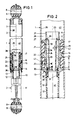
- Fig. 2 einen Teil-Längsschnitt des Reibungsdämpfers in gegenüber Fig. 1 vergrößertem Maßstab.
- Fig. 1 shows a friction damper according to the invention in longitudinal section and
- Fig. 2 is a partial longitudinal section of the friction damper on an enlarged scale compared to Fig. 1.
Der in der Zeichnung dargestellte Reibungsdämpfer weist ein Gehäuse 1 und einen Stößel 2 auf. Das Gehäuse 1 besteht im wesentlichen aus einem zylindrischen metallischen Rohr 3, das an einem Ende mittels eines Bodens 4 verschlossen ist. An der Außenseite des Bodens 4 ist eine Gelenkbüchse 5 zum Anlenken des Reibungsdämpfer angebracht. Diese Gelenkbüchse 5 weist eine als Schwenkachse dienende Symmetrieachse 6 auf, die die Mittel-Längs-Achse 7 des Reibungsdämpfers senkrecht schneidet.The friction damper shown in the drawing has a
Der Stößel 2 weist an seinem äußeren Ende ebenfalls eine Gelenkbüchse 8 auf, deren Achse 9 ebenfalls die Mittel-Längs-Achse 7 senkrecht schneidet. Der Stößel 2 selber besteht im wesentlichen aus einem sich zur Gelenkbüchse 8 hin verjüngenden Rohr 10, das auf seiner Außenseite mittels Längsrippen 11 versteift ist. Das Rohr 10 ist mit einer Entlüftungsöffnung 12 versehen. Der Stößel 2 ist einstückig aus Kunststoff gespritzt.The
Am im Gehäuse 1 befindlichen inneren Ende des Stößels 2 ist ein Reibungskolben 13 ausgebildet, der ringförmige, im Abstand voneinander ausgebildete und einander paarweise zugeordnete Gegenhalteflansche 14, 15 und 16, 17 aufweist. Zwischen den einander jeweils zugeordneten Gegenhalteflanschen 14, 15 bzw. 16, 17 sind etwa kreiszylindrische Auflage-Abschnitte 18, 19 ausgebildet, die ebenfalls konzentrisch zur Achse 7 angeordnet sind. Auf den Auflage-Abschnitten 18, 19 ist jeweils ein Reibungsbelag 20, 21 angeordnet. Diese Reibungsbeläge 20, 21 bestehen aus einem zelligen, elastischen Schaumstoff, beispielsweise einem Polyuretan-Schaumstoff.At the inner end of the
Zwischen den beiden einander benachbarten Gegenhalteflanschen 15, 16, also auch zwischen den Reibungsbelägen 20, 21 ist eine im Verhältnis zum Volumen eines Reibbelages 20 bzw. 21 relativ kleinvolumige ringnutförmige Schmierfett-Kammer 22 ausgebildet.Between the two mutually
An der Innenseite des Reibungskolbens 13 ist eine relativ großvolumige Schmierfett-Vorratskammer 23 ausgebildet. Diese wird an ihrer Außenseite durch die Innenwand 24 des Reibungskolbens 13 und an ihrer Innenseite und im Bereich ihrer axialen Enden durch einen Einsatzkörper 25 begrenzt. Dieser Einsatzkörper 25 liegt mit einem Ringbund 26 an der Stirnseite 27 des Reibungskolbens 13 und dem hierzu benachbarten Bereich der Innenwand 24 an, so daß er hier zum einen radial und zum anderen axial in Richtung zur Gelenkbüchse 8 gegenüber dem Reibungskolben 13 festgelegt ist.A relatively large-volume
An seinem anderen, der Gelenkbüchse 8 zugewandten Ende weist der Einsatzkörper 25 einen Zylinderabschnitt 28 auf, in dem eine Ringnut 29 ausgebildet ist. In dieser befindet sich eine O-Ring-Dichtung 30, die gegen die Innenwand 24 des Reibungskolbens 13 anliegt und zwar im Bereich des Gegenhalteflansches 14, der der Gelenkbüchse 8 nächstgelegen ist. Die Vorratskammer 23 erstreckt sich also etwa über die gesamte axiale Erstreckung des Reibungskolbens 13.At its other end, which faces the
An den Zylinderabschnitt 28 schließen sich zwei Befestigungsstege 31 an, die jeweils einen widerhakenartigen radial nach außen vorspringenden Vorsprung 32 aufweisen, der jeweils in montiertem Zustand des Einsatzkörpers 25 in eine entsprechende Ausnehmung 33 im Rohr 10 des Stößels 2 einrastet. Die Befestigungsstege 31 sind so ausgebildet, daß sie beim Einschieben des Einsatzkörpers 25 in den Stößel 2 radial nach innen elastisch ausgelenkt werden. Dies ist dadurch möglich, daß der gesamte Einsatzkörper 25 einstückig aus einem geeigneten elastischen Kunststoff hergestellt wird. Die Ausnehmungen 33 können gleichzeitig als Entlüftungsöffnungen dienen, so daß die Entlüftungsöffnung 12 als zusätzliche Öffnung entfallen kann.The cylinder section 28 is followed by two
Im Reibungskolben 13 sind im Bereich der Auflage-Abschnitte 18, 19 Schmierfett-Kanäle 34 ausgebildet, die die Vorratskammer 23 mit den Reibungsbelägen 20 bzw. 21 verbinden. Der Durchmesser d dieser Kanäle beträgt etwa 1,0 bis 1, 5 mm, wobei sich der Durchmesser d und die Zahl der Kanäle 34 pro Auflage-Abschnitt 18 bzw. 19 im wesentlichen nach der Viskosität des in der Vorratskammer 23 befindlichen Schmierfettes 35 richtet.
Es ist nicht zweckmäßig, den Durchmesser d der Kanäle 34 nennenswert größer als 1,5 mm zu machen, da sonst die Reibungsbeläge 20, 21 mangels Abstützung im Bereich der Kanäle 34 ihr Reibverhalten gegenüber der Innenwand 36 des Gehäuses 1 verändern würden.It is not expedient to make the diameter d of the
Das Schmierfett 35 wandert durch die Kanäle 34 in den Bereich der Auflage-Abschnitte 18, 19 und von dort durch die Reibungsbeläge 20, 21 hindurch zur Reibfläche zwischen den Reibbelägen 20, 21 und der Innenwand 36 des Gehäuses 1. Um dies zu ermöglichen, ist der die Reibungsbeläge 20, 21 bildende Schaumstoff zumindest teilweise offenzellig ausgebildet, was gerade bei Polyuretan-Schaumstoff der Fall ist.The lubricating
Am inneren Ende des Einsatzkörpers 25 ist an diesem einstückig ein Verlängerungsstutzen 37 angeformt, der sich axial um ein Maß a über den endseitigen Gegenhalteflansch 17 erstreckt, das etwa der axialen Länge b der Reibungsbeläge 20 bzw. 21 entspricht. Durch diesen Verlängerungsstutzen 37, den zugeordneten Gegenhalteflansch 17 und die Innenwand 36 des Rohres 3 wird eine Schmierfett-Sammelkammer 38 gebildet.At the inner end of the
Das Rohr 3 ist an seinem offenen Ende mit einer nach innen gerichteten Sicke 39 versehen, die nach dem Einschieben des Stößels 2 in das Gehäuse 1 angebracht wird, um ein unbeabsichtigtes Ausziehen des Stößels 2 aus dem Gehäuse 1 zu verhindern.The
Der Einsatzkörper 25 ist hohl, also etwa rohrförmig ausgebildet, so daß der Innenraum 40 des Gehäuses 1 mit dem Innenraum 41 des Stößels 2 verbunden ist; bei oszillierenden Bewegungen des Stößels 2 relativ zum Gehäuse 1 erfolgt also keine Kompression der im Reibungsdämpfer befindlichen Luft; es kann vielmehr eine ständig wechselnde Luftströmung aus dem Reibungsdämpfer hinaus bzw. in diesen hinein über die Entlüftungsöffnung 12 und/oder die Ausnehmungen 33 erfolgen.The
Wenn die Durchlässigkeit des Reibungsbelages 20, 21 nicht ausreichend ist, um genügend Schmierfett 35 aus der Vorratskammer 23 zum Reibungsbereich zwischen dem Reibungsbelag 20 bzw. 21 einerseits und der Innenwand 36 des Gehäuses 1 andererseits zu transportieren, dann kann es zweckmäßig sein, in den bzw. die Reibungsbeläge 20, 21 mindestens eine Öffnung 42, beispielsweise durch Stanzen, einzubringen. Eine solche Öffnung 42 sollte derart angeordnet sein, daß sie sich mit mindestens einem Schmierfett-Kanal 34 zumindest teilweise überdeckt, so daß der Schmierfett-Transport sichergestellt ist. Hierzu ist es zweckmäßig, wenn ihre Weite bzw. ihr Durchmesser e gleich oder größer dem Durchmesser d des Kanals 34 ist. Außerdem sollte die Öffnung 42 in der Ebene eines Kanals 34 angeordnet sein.If the permeability of the
Claims (13)
Applications Claiming Priority (2)
| Application Number | Priority Date | Filing Date | Title |
|---|---|---|---|
| DE3923087A DE3923087A1 (en) | 1989-07-13 | 1989-07-13 | FRICTION DAMPER |
| DE3923087 | 1989-07-13 |
Publications (3)
| Publication Number | Publication Date |
|---|---|
| EP0407793A2 true EP0407793A2 (en) | 1991-01-16 |
| EP0407793A3 EP0407793A3 (en) | 1992-01-02 |
| EP0407793B1 EP0407793B1 (en) | 1994-08-24 |
Family
ID=6384905
Family Applications (1)
| Application Number | Title | Priority Date | Filing Date |
|---|---|---|---|
| EP90111953A Expired - Lifetime EP0407793B1 (en) | 1989-07-13 | 1990-06-23 | Friction damper |
Country Status (6)
| Country | Link |
|---|---|
| US (1) | US5085297A (en) |
| EP (1) | EP0407793B1 (en) |
| DD (1) | DD296534A5 (en) |
| DE (2) | DE3923087A1 (en) |
| TR (1) | TR26232A (en) |
| YU (1) | YU134190A (en) |
Cited By (2)
| Publication number | Priority date | Publication date | Assignee | Title |
|---|---|---|---|---|
| EP0478983A2 (en) * | 1990-09-29 | 1992-04-08 | SUSPA COMPART Aktiengesellschaft | Friction damper |
| EP0535443A1 (en) * | 1991-10-02 | 1993-04-07 | SUSPA COMPART Aktiengesellschaft | Friction damper for washing machines |
Families Citing this family (5)
| Publication number | Priority date | Publication date | Assignee | Title |
|---|---|---|---|---|
| US5183137A (en) * | 1991-12-20 | 1993-02-02 | Lord Corporation | Dual-rate surface effect dampers |
| US6279693B1 (en) * | 1998-02-26 | 2001-08-28 | Kasgro Rail Corp. | Friction dampener particularly adapted to railway vehicle motion control |
| US7281614B2 (en) * | 2003-10-06 | 2007-10-16 | Lg Electronics Inc. | Damper in a washing machine and fabricating method of the same |
| DE102006025749A1 (en) * | 2006-05-31 | 2007-12-13 | Suspa Holding Gmbh | damper |
| DE102016210162A1 (en) * | 2016-06-08 | 2017-12-14 | Suspa Gmbh | Guide / damping unit and piston housing unit |
Citations (1)
| Publication number | Priority date | Publication date | Assignee | Title |
|---|---|---|---|---|
| DE3604286A1 (en) * | 1985-03-26 | 1986-10-09 | Fritz Bauer + Söhne oHG, 8503 Altdorf | FRICTION DAMPER, ESPECIALLY FOR WASHING MACHINES WITH SPIN |
Family Cites Families (6)
| Publication number | Priority date | Publication date | Assignee | Title |
|---|---|---|---|---|
| US1510825A (en) * | 1924-03-19 | 1924-10-07 | Bousquet Ralph | Transmission-drum band |
| US2856050A (en) * | 1953-05-20 | 1958-10-14 | Gen Motors Corp | Friction clutch with lubricating means for clutch facer |
| FR1336185A (en) * | 1962-07-09 | 1963-08-30 | Shock absorber improvements | |
| FR1570563A (en) * | 1968-03-25 | 1969-06-13 | ||
| DE2835300A1 (en) * | 1978-08-11 | 1980-02-28 | Quick Rotan Becker & Notz Kg | DRIVE DEVICE WITH FRICTION CLUTCH |
| DE3834127A1 (en) * | 1988-10-07 | 1990-04-12 | Bauer Fritz & Soehne Ohg | FRICTION DAMPER |
-
1989
- 1989-07-13 DE DE3923087A patent/DE3923087A1/en not_active Withdrawn
-
1990
- 1990-06-23 EP EP90111953A patent/EP0407793B1/en not_active Expired - Lifetime
- 1990-06-23 DE DE59006885T patent/DE59006885D1/en not_active Expired - Fee Related
- 1990-07-11 YU YU134190A patent/YU134190A/en unknown
- 1990-07-11 DD DD90342700A patent/DD296534A5/en not_active IP Right Cessation
- 1990-07-11 US US07/551,222 patent/US5085297A/en not_active Expired - Fee Related
- 1990-07-12 TR TR90/0656A patent/TR26232A/en unknown
Patent Citations (1)
| Publication number | Priority date | Publication date | Assignee | Title |
|---|---|---|---|---|
| DE3604286A1 (en) * | 1985-03-26 | 1986-10-09 | Fritz Bauer + Söhne oHG, 8503 Altdorf | FRICTION DAMPER, ESPECIALLY FOR WASHING MACHINES WITH SPIN |
Cited By (3)
| Publication number | Priority date | Publication date | Assignee | Title |
|---|---|---|---|---|
| EP0478983A2 (en) * | 1990-09-29 | 1992-04-08 | SUSPA COMPART Aktiengesellschaft | Friction damper |
| EP0478983A3 (en) * | 1990-09-29 | 1993-01-20 | Suspa Compart Aktiengesellschaft | Friction damper |
| EP0535443A1 (en) * | 1991-10-02 | 1993-04-07 | SUSPA COMPART Aktiengesellschaft | Friction damper for washing machines |
Also Published As
| Publication number | Publication date |
|---|---|
| TR26232A (en) | 1995-02-15 |
| EP0407793B1 (en) | 1994-08-24 |
| YU134190A (en) | 1994-04-05 |
| US5085297A (en) | 1992-02-04 |
| DE59006885D1 (en) | 1994-09-29 |
| DE3923087A1 (en) | 1991-01-24 |
| DD296534A5 (en) | 1991-12-05 |
| EP0407793A3 (en) | 1992-01-02 |
Similar Documents
| Publication | Publication Date | Title |
|---|---|---|
| EP0478983B1 (en) | Friction damper | |
| EP0336176B1 (en) | Friction damper | |
| EP1162338B1 (en) | Shock absorbing device, especially for cabinet doors or drawers | |
| EP0806514A2 (en) | Friction damper, in particular for washing machines with a spin phase | |
| DE2341352C2 (en) | Blockable lifting unit with end suspension | |
| DE2950888A1 (en) | SHOCK PISTON FOR PNEUMATIC, HYDRAULIC AND HYDROPNEUMATIC AGGREGATE | |
| DE3002715C2 (en) | Sealing arrangement | |
| DE3616844C2 (en) | Guide and seal arrangement for the piston rod of a piston-cylinder unit | |
| DE2749268C2 (en) | ||
| DE3039801A1 (en) | PISTON FOR A PNEUMATIC, HYDRAULIC OR HYDROPNEUMATIC AGGREGATE | |
| EP0217013B1 (en) | Gas spring adjustable in length | |
| DE3442651C2 (en) | ||
| DE2038580B2 (en) | Aerosol container valve | |
| EP0407793B1 (en) | Friction damper | |
| DE60209678T2 (en) | Lubricating device for spherical bearings | |
| EP0901452B1 (en) | Multi-chamber ampoule for measured doses of liquids | |
| EP0362540B1 (en) | Friction damper | |
| DE2656822A1 (en) | Roller or ball bearings - are of elastomeric material with intermediate smaller harder roller or ball to eliminate play | |
| DE3725101A1 (en) | PISTON FOR PISTON-CYLINDER UNIT | |
| DE4024382C1 (en) | ||
| EP0527701B1 (en) | Piston compressor for oil-free gas compression | |
| DE3008403A1 (en) | RELEASER FOR CLUTCHES, ESPECIALLY FOR MOTOR VEHICLE CLUTCHES | |
| WO2003100287A1 (en) | Damping device for moveable furniture parts of pieces of furniture | |
| DE19822805C2 (en) | Sealing arrangement | |
| DE3731710A1 (en) | Bearing arrangement for an axially compact miniature fan |
Legal Events
| Date | Code | Title | Description |
|---|---|---|---|
| PUAI | Public reference made under article 153(3) epc to a published international application that has entered the european phase |
Free format text: ORIGINAL CODE: 0009012 |
|
| AK | Designated contracting states |
Kind code of ref document: A2 Designated state(s): DE ES FR GB IT |
|
| 17P | Request for examination filed |
Effective date: 19901129 |
|
| RAP1 | Party data changed (applicant data changed or rights of an application transferred) |
Owner name: SUSPA COMPART AKTIENGESELLSCHAFT |
|
| PUAL | Search report despatched |
Free format text: ORIGINAL CODE: 0009013 |
|
| AK | Designated contracting states |
Kind code of ref document: A3 Designated state(s): DE ES FR GB IT |
|
| 17Q | First examination report despatched |
Effective date: 19940209 |
|
| GRAA | (expected) grant |
Free format text: ORIGINAL CODE: 0009210 |
|
| AK | Designated contracting states |
Kind code of ref document: B1 Designated state(s): DE ES FR GB IT |
|
| PG25 | Lapsed in a contracting state [announced via postgrant information from national office to epo] |
Ref country code: GB Effective date: 19940824 Ref country code: ES Free format text: THE PATENT HAS BEEN ANNULLED BY A DECISION OF A NATIONAL AUTHORITY Effective date: 19940824 |
|
| REF | Corresponds to: |
Ref document number: 59006885 Country of ref document: DE Date of ref document: 19940929 |
|
| ITF | It: translation for a ep patent filed |
Owner name: ING. C. GREGORJ S.P.A. |
|
| ET | Fr: translation filed | ||
| GBV | Gb: ep patent (uk) treated as always having been void in accordance with gb section 77(7)/1977 [no translation filed] |
Effective date: 19940824 |
|
| PLBE | No opposition filed within time limit |
Free format text: ORIGINAL CODE: 0009261 |
|
| STAA | Information on the status of an ep patent application or granted ep patent |
Free format text: STATUS: NO OPPOSITION FILED WITHIN TIME LIMIT |
|
| 26N | No opposition filed | ||
| PG25 | Lapsed in a contracting state [announced via postgrant information from national office to epo] |
Ref country code: FR Effective date: 19960229 |
|
| PG25 | Lapsed in a contracting state [announced via postgrant information from national office to epo] |
Ref country code: DE Effective date: 19960301 |
|
| REG | Reference to a national code |
Ref country code: FR Ref legal event code: ST |
|
| PG25 | Lapsed in a contracting state [announced via postgrant information from national office to epo] |
Ref country code: IT Free format text: LAPSE BECAUSE OF NON-PAYMENT OF DUE FEES;WARNING: LAPSES OF ITALIAN PATENTS WITH EFFECTIVE DATE BEFORE 2007 MAY HAVE OCCURRED AT ANY TIME BEFORE 2007. THE CORRECT EFFECTIVE DATE MAY BE DIFFERENT FROM THE ONE RECORDED. Effective date: 20050623 |