EP0407740A1 - Vehicle jack - Google Patents
Vehicle jack Download PDFInfo
- Publication number
- EP0407740A1 EP0407740A1 EP90110960A EP90110960A EP0407740A1 EP 0407740 A1 EP0407740 A1 EP 0407740A1 EP 90110960 A EP90110960 A EP 90110960A EP 90110960 A EP90110960 A EP 90110960A EP 0407740 A1 EP0407740 A1 EP 0407740A1
- Authority
- EP
- European Patent Office
- Prior art keywords
- support plate
- support arm
- support
- eyelets
- axis
- Prior art date
- Legal status (The legal status is an assumption and is not a legal conclusion. Google has not performed a legal analysis and makes no representation as to the accuracy of the status listed.)
- Granted
Links
Images
Classifications
-
- B—PERFORMING OPERATIONS; TRANSPORTING
- B66—HOISTING; LIFTING; HAULING
- B66F—HOISTING, LIFTING, HAULING OR PUSHING, NOT OTHERWISE PROVIDED FOR, e.g. DEVICES WHICH APPLY A LIFTING OR PUSHING FORCE DIRECTLY TO THE SURFACE OF A LOAD
- B66F3/00—Devices, e.g. jacks, adapted for uninterrupted lifting of loads
- B66F3/08—Devices, e.g. jacks, adapted for uninterrupted lifting of loads screw operated
- B66F3/12—Devices, e.g. jacks, adapted for uninterrupted lifting of loads screw operated comprising toggle levers
-
- Y—GENERAL TAGGING OF NEW TECHNOLOGICAL DEVELOPMENTS; GENERAL TAGGING OF CROSS-SECTIONAL TECHNOLOGIES SPANNING OVER SEVERAL SECTIONS OF THE IPC; TECHNICAL SUBJECTS COVERED BY FORMER USPC CROSS-REFERENCE ART COLLECTIONS [XRACs] AND DIGESTS
- Y10—TECHNICAL SUBJECTS COVERED BY FORMER USPC
- Y10S—TECHNICAL SUBJECTS COVERED BY FORMER USPC CROSS-REFERENCE ART COLLECTIONS [XRACs] AND DIGESTS
- Y10S254/00—Implements or apparatus for applying pushing or pulling force
- Y10S254/04—Object engaging heads for jacks
Definitions
- the invention relates to a jack with at least one main leg and a support arm connected to it in a vertically movable manner, the position of which can be changed by means of an adjusting device and in the region of its outer free end has a support plate which is connected to the support arm by means of an approximately horizontally extending axis is.
- a jack of the type mentioned at the beginning (DE PS 28 01 735) is already known, which has an axis of rotation at its outer free end which serves to receive a support plate.
- the axis of rotation for receiving the support plate is rigidly connected to the support arm, so that when lifting a vehicle with the jack, side forces can occur which can twist the jack or the supporting parts.
- Such side forces occur in particular when, for example, the jack must be set up obliquely with respect to the vehicle on a rising road.
- one-sided loading of the support plate can occur, so that the support plate can then be damaged, in particular the tabs, which connect the support plate to the associated bolt attached to the support arm.
- the tabs surrounding the bolt or the axle can be bent open.
- the object of the invention is to design and arrange the support plate which is movable on the support arm in such a way that no damage to the support plate or the connections between the support plate and support arm can occur even when the support plate is subjected to one-sided loading.
- This object is stated in the characterizing part of claim 1 characteristics solved.
- the advantageous design of the eyelets punched out of the support plate part, which remain connected in one piece to the support plate at the end, ensures that the axle is held securely, so that even when the support plate is loaded on one side, the axle is not levered out of the eyelet, particularly when the car owner is tilted. since these can no longer be bent open. This is achieved in particular in that the ends of the eyelets remain in one piece with the parts of the support plate even after punching out, and thus a permanent connection is ensured between the ends of the eyelets and the support plate.
- eyelets receiving the support plate and axle can also be preassembled as an assembly according to claim 2 and then firmly connect the assembly to the support arm, for which purpose the axle is butt welded to legs of the support arm, for example.
- the eyelets which are arranged at a distance from one another, come into contact after mounting of the support plate on the support arm against parallel legs of the support arm, so that lateral adjustment of the support plate is prevented.
- the axle has, as an alternative to receiving the eyelets, groove-shaped depressions which prevent the support plate from being displaced on the axle.
- the eyelets are arranged on the underside of the support plate, so that a flat contact surface is ensured on the support plate.
- 10 denotes a jack, which consists of a support leg 12 and a support arm 16 which is connected to it by means of an articulated bolt 14 and can be pivoted vertically.
- the supporting leg 12 has a storage plate 18 with a roller foot 20 at its lower end. With the parking plate 18, the jack 10 is parked on the floor when attached to the motor vehicle.
- a stand plate 22 arranged at an angle to the positioning plate 18 is also provided on the roller foot 20.
- an adjusting device 26 which is designed as a threaded spindle 27 and is pivotably mounted with the aid of a spindle nut 28.
- the spindle nut 28 has pins 30 on both sides, by means of which the spindle nut 28 is received in side cheeks 32 of the supporting leg 12.
- the support arm 16 is articulated via a spindle abutment, not shown, for. B. a roller bearing, one bearing disc is acted upon by the threaded spindle 27 and the other bearing disc has pins 34 which engage in the side walls 54 of the U-shaped support arm 16.
- the support arm 16 is connected in an articulated manner to the support leg 12 via the hinge pin 14 and, according to the adjusting device 26, carries out pivoting movements relative to the support leg 12.
- the support plate 40 has a recess 42 for receiving a sill seam of a vehicle floor, not shown in the drawing.
- a support surface 44 adjoins the recess 42 of the support plate 40, which can lie against a vehicle floor in such a way that the sill seam of the motor vehicle remains free from the support plate 40.
- the support surface is dimensioned as large as possible.
- two eyelets 50 arranged at a distance from one another are punched into the support surface 44 of the support plate 40, the ends of the eyelets 50 remaining connected in one piece to parts of the support plate.
- the eyelets 50 provided on the underside of the support surface 44 serve to receive an axle or a bolt 52.
- the support plate 40 and the axle 52 can be designed as a preassembled module, so that these then easily connect to the front end of the support arm 16 leaves.
- a firm connection between the support plate 40 and the front end of the support arm 16 is obtained in that the axis 52 is butt welded to side walls 54 of the support arm 16.
- the distance between the inner surfaces of the eyelets 50 is slightly larger than the distance between the outer surfaces of the side cheeks 54, so that when the support plate 40 is connected to the front end of the support arm 16, the inner surfaces of the eyelets 50 against the outer surfaces of the side cheeks 54 come to rest and thus prevent displacement of the support plate 40 on the bolt or the axis 52.
- Securing in the axial direction of the support plate 40 is also possible in that groove-shaped depressions are provided in the bolt, into which the eyelets 50 can snap. For this purpose, after inserting the axis 52 into the eyelets 50, the eyelets are pressed together until they engage in the grooves provided.
Abstract
Die Erfindung bezieht sich auf einen Wagenheber 10, an dem ein Tragarm 16 mittels eines Gelenkbolzens 14 schwenkbar angeschlossen ist. Am vorderen Ende des Tragarmes 16 befindet sich eine vertikal schwenkbare Tragplatte 40, die über eine Achse 52 mit dem Tragarm 16 gelenkig verbunden ist. Hierzu weist die Tragplatte 40 an der Unterseite zwei mit Abstand zueinander angeordnete nach unten herausgestanzte Ösen 50 auf, in die die Achse 52 eingeschoben ist. Die Achse 52 ist mit Seitenwangen 54 des Tragarmes 16 fest verschweißt.The invention relates to a jack 10 to which a support arm 16 is pivotally connected by means of a hinge pin 14. At the front end of the support arm 16 there is a vertically pivotable support plate 40 which is articulated to the support arm 16 via an axis 52. For this purpose, the support plate 40 has on the underside two eyelets 50, which are spaced apart and punched out and into which the axis 52 is inserted. The axis 52 is welded to the side walls 54 of the support arm 16.
Description
Die Erfindung bezieht sich auf einen Wagenheber mit mindestens einem Standbein und einem daran höhenbeweglich angeschlossenen Tragarm, der mittels einer Stellvorrichtung in seiner Lage veränderbar ist und im Bereich seines äußeren freien Endes eine Tragplatte aufweist, die mittels einer in etwa horizontal verlaufenden Achse an den Tragarm angeschlossen ist.The invention relates to a jack with at least one main leg and a support arm connected to it in a vertically movable manner, the position of which can be changed by means of an adjusting device and in the region of its outer free end has a support plate which is connected to the support arm by means of an approximately horizontally extending axis is.
Es ist bereits ein Wagenheber der eingangs aufgeführten Art (DE PS 28 01 735) bekannt, der an seinem äußeren freien Ende eine Drehachse aufweist, die zur Aufnahme einer Tragplatte dient. Die Drehachse zur Aufnahme der Tragplatte ist jedoch starr mit dem Tragarm verbunden, so daß beim Anheben eines Fahrzeuges mit dem Wagenheber Seitenkräfte auftreten können, die den Wagenheber bzw. die tragenden Teile verwinden können. Derartige Seitenkräfte treten insbesondere dann auf, wenn beispielsweise an einer ansteigenden Straße der Wagenheber mit Bezug auf das Fahrzeug schräg aufgestellt werden muß. In einem derartigen Fall kann es zur einseitigen Belastung der Tragplatte kommen, so daß dann die Tragplatte beschädigt werden kann, insbesondere die Laschen, die die Tragplatte mit dem zugehörigen am Tragarm befestigten Bolzen verbinden. Bei sehr starker einseitiger Belastung können die den Bolzen bzw. die Achse umgebenden Laschen aufgebogen werden.A jack of the type mentioned at the beginning (
Demgegenüber liegt der Erfindung die Aufgabe zugrunde die am Tragarm bewegliche angeordnete Tragplatte derart auszubilden und anzuordnen, daß auch bei einseitiger Belastung der Tragplatte keine Beschädigungen der Tragplatte bzw. der Verbindungen zwischen Tragplatte und Tragarm auftreten können. Diese Aufgabe ist durch die im kennzeichnenden Teil des Anspruches 1 aufgeführ ten Merkmale gelöst. Durch die vorteilhafte Ausbildung der aus dem Tragplattenteil herausgestanzten Ösen, die endseitig einteilig mit der Tragplatte verbunden bleiben, erhält man eine sichere Aufnahme der Achse, so daß auch bei einseitiger Belastung der Tragplatte insbesondere bei Schrägstellung des Wagenhabers kein Aushebeln der Achse aus der Öse erfolgt, da diese sich nunmehr nicht mehr aufbiegen lassen. Dies wird insbesondere dadurch erreicht, daß die Enden der Ösen mit den Teilen der Tragplatte auch nach Herausstanzen einteilig verbunden bleiben und somit zwischen den Enden der Ösen und der Tragplatte eine dauerhafte Verbindung sichergestellt ist.In contrast, the object of the invention is to design and arrange the support plate which is movable on the support arm in such a way that no damage to the support plate or the connections between the support plate and support arm can occur even when the support plate is subjected to one-sided loading. This object is stated in the characterizing part of claim 1 characteristics solved. The advantageous design of the eyelets punched out of the support plate part, which remain connected in one piece to the support plate at the end, ensures that the axle is held securely, so that even when the support plate is loaded on one side, the axle is not levered out of the eyelet, particularly when the car owner is tilted. since these can no longer be bent open. This is achieved in particular in that the ends of the eyelets remain in one piece with the parts of the support plate even after punching out, and thus a permanent connection is ensured between the ends of the eyelets and the support plate.
Durch die vorteilhafte Ausgestaltung der die Achse aufnehmenden Ösen lassen sich Tragplatte und Achse auch als Baugruppe gemäß Anspruch 2 vormontieren und dann die Baugruppe mit dem Tragarm fest verbinden, wozu die Achse beispielsweise stumpf an Schenkeln des Tragarmes angeschweißt wird.Due to the advantageous design of the eyelets receiving the support plate and axle can also be preassembled as an assembly according to claim 2 and then firmly connect the assembly to the support arm, for which purpose the axle is butt welded to legs of the support arm, for example.
In weiterer Ausgestaltung der Erfindung ist es vorteilhaft, daß die mit Abstand zueinander angeordneten Ösen nach der Montage der Tragplatte am Tragarm gegen parallel verlaufende Schenkel des Tragarmes zur Anlage kommen, so daß eine Seitenverstellung der Tragplatte verhindert wird. Hierzu ist es ferner vorteilhaft, daß die Achse alternativ zur Aufnahme der Ösen rillenförmige Vertiefungen aufweist, die ein Verschieben der Tragplatte auf der Achse verhindern. Außerdem ist es vorteilhaft, daß die Ösen an der Unterseite der Tragplatte angeordnet sind, so daß eine plane Auflagefläche an der Tragplatte gewährleistet ist.In a further embodiment of the invention, it is advantageous that the eyelets, which are arranged at a distance from one another, come into contact after mounting of the support plate on the support arm against parallel legs of the support arm, so that lateral adjustment of the support plate is prevented. For this purpose, it is also advantageous that the axle has, as an alternative to receiving the eyelets, groove-shaped depressions which prevent the support plate from being displaced on the axle. It is also advantageous that the eyelets are arranged on the underside of the support plate, so that a flat contact surface is ensured on the support plate.
Nachfolgend ist die Erfindung anhand eines in der Zeichnung schematisch dargestellten Ausführungsbeispiels näher erläutert. Es zeigen:
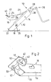
- Fig. 1 Eine schematische Darstellung eines Wagenhebers mit an einem Tragarm beweglich angeordneter Tragplatte,
- Fig. 2 Eine perspektivische Darstellung des vorderen Endes der Tragplatte und des Tragarmes in der Ansicht von unten
- 1 is a schematic representation of a jack with a support plate movably arranged on a support arm,
- Fig. 2 is a perspective view of the front end of the support plate and the support arm in a view from below
In der Zeichnung ist mit 10 ein Wagenheber bezeichnet, der aus einem Standbein 12 und an diesem mittels eines Gelenkbolzens 14 vertikal schwenkbar angeschlossenen Tragarm 16 besteht. Das Standbein 12 weist an seinem unteren Ende eine Abstellplatte 18 mit einem Wälzfuß 20 auf. Mit der Abstellplatte 18 wird der Wagenheber 10 beim Ansetzen am Kraftfahrzeug auf dem Boden abgestellt. An dem Wälzfuß 20 ist ferner eine im Winkel zur Anstellplatte 18 angeordnete Standplatte 22 vorgesehen.In the drawing, 10 denotes a jack, which consists of a
Am oberen Ende des beispielsweise U-förmig ausgebildeten Standbeins 12 befindet sich eine als Gewindespindel 27 ausgebildete Stellvorrichtung 26, die mit Hilfe einer Spindelmutter 28 schwenkbar gelagert ist. Die Spindelmutter 28 weist beidseitig Zapfen 30 auf, mittels der die Spindelmutter 28 in Seitenwangen 32 des Standbeines 12 aufgenommen ist.At the upper end of the
Am unteren Ende der Gewindespindel 27 ist der Tragarm 16 über ein nicht näher dargestelltes Spindelwiderlager angelenkt, z. B. ein Wälzlager, dessen eine Lagerscheibe von der Gewindespindel 27 beaufschlagt wird und dessen andere Lagerscheibe Zapfen 34 aufweist, die in den Seitenwangen 54 des U-förmigen Tragarmes 16 eingreifen.At the lower end of the threaded
Wie aus Fig. 1 hervorgeht, ist der Tragarm 16 über den Gelenkbolzen 14 mit dem Standbein 12 gelenkig verbunden und führt entsprechend der Stellvorrichtung 26 Schwenkbewegungen relativ zum Standbein 12 aus.As can be seen from FIG. 1, the
Am freien Ende des Tragarmes 16 befindet sich eine Tragplatte 40, mit der der Wagenheber 10 an einen Fahrzeugboden eines Kraftfahrzeuges angesetzt werden kann. Die Tragplatte 40 hat eine Vertiefung 42 zur Aufnahme einer Schwellernaht eines in der Zeichnung nicht dargestellten Fahrzeugbodens. An die Vertiefung 42 der Tragplatte 40 schließt sich eine Abstützfläche 44 an, die sich derart an einen Fahrzeugboden anlegen kann, daß die Schwellernaht des Kraftfahrzeuges von der Tragplatte 40 frei bleibt. Zur Verringerung der Flächenpressung am Fahrzeugboden ist die Abstützfläche so groß wie möglich bemessen.At the free end of the
Wie insbesondere aus Fig. 2 hervorgeht, sind in der Abstützfläche 44 der Tragplatte 40 zwei mit Abstand zueinander angeordnete Ösen 50 eingestanzt, wobei die Enden der Ösen 50 mit Teilen der Tragplatte einteilig verbunden bleiben. Die an der Unterseite der Abstützfläche 44 vorgesehenen Ösen 50 dienen zur Aufnahme einer Achse bzw. eines Bolzens 52. Die Tragplatte 40 sowie die Achse 52 können als vormontierbare Baugruppe ausgebildet sein, so daß sich diese dann ohne weiteres an das vordere Ende des Tragarmes 16 anschließen läßt. Eine feste Verbindung zwischen der Tragplatte 40 und dem vorderen Ende des Tragarmes 16 erhält man dadurch, daß die Achse 52 mit Seitenwangen 54 des Tragarmes 16 stumpf verschweißt sind. Der Abstand zwischen den innenliegenden Flächen der Ösen 50 ist etwas größer als der Abstand zwischen den außenliegenden Flächen der Seitenwangen 54, so daß bei der Verbindung der Tragplatte 40 mit dem vorderen Ende des Tragarmes 16 die innenliegenden Flächen der Ösen 50 gegen die außenliegenden Flächen der Seitenwangen 54 zur Anlage kommen und somit eine Verschiebung der Tragplatte 40 auf dem Bolzen bzw. der Achse 52 verhindern. Eine Sicherung in Axialrichtung der Tragplatte 40 ist auch dadurch möglich, daß in dem Bolzen rillenförmige Vertiefungen vorgesehen werden, in die die Ösen 50 einrasten können. Hierzu werden nach Einführung der Achse 52 in die Ösen 50 die Ösen so weit zusammengedrückt, bis sie in die vorgesehenen Rillen eingreifen.As can be seen in particular from FIG. 2, two
Claims (5)
Applications Claiming Priority (2)
| Application Number | Priority Date | Filing Date | Title |
|---|---|---|---|
| DE3921826 | 1989-07-03 | ||
| DE3921826A DE3921826C1 (en) | 1989-07-03 | 1989-07-03 |
Publications (2)
| Publication Number | Publication Date |
|---|---|
| EP0407740A1 true EP0407740A1 (en) | 1991-01-16 |
| EP0407740B1 EP0407740B1 (en) | 1993-08-11 |
Family
ID=6384188
Family Applications (1)
| Application Number | Title | Priority Date | Filing Date |
|---|---|---|---|
| EP90110960A Expired - Lifetime EP0407740B1 (en) | 1989-07-03 | 1990-06-09 | Vehicle jack |
Country Status (8)
| Country | Link |
|---|---|
| US (1) | US5011118A (en) |
| EP (1) | EP0407740B1 (en) |
| JP (1) | JP2703396B2 (en) |
| BR (1) | BR9003135A (en) |
| DD (1) | DD297945A5 (en) |
| DE (2) | DE3921826C1 (en) |
| ES (1) | ES2019575T3 (en) |
| ZA (1) | ZA905022B (en) |
Cited By (2)
| Publication number | Priority date | Publication date | Assignee | Title |
|---|---|---|---|---|
| DE19625281A1 (en) * | 1996-06-25 | 1998-01-08 | Storz E A Kg | Jack especially for road vehicle |
| WO2003037776A1 (en) * | 2001-10-27 | 2003-05-08 | Thyssenkrupp Bilstein Gmbh | Lift jack comprising a support arm and method for producing said support arm |
Families Citing this family (10)
| Publication number | Priority date | Publication date | Assignee | Title |
|---|---|---|---|---|
| DE4127739C2 (en) * | 1991-08-22 | 1993-11-11 | Bilstein August Gmbh Co Kg | Jack |
| JPH0556891U (en) * | 1992-01-09 | 1993-07-27 | 黄陳 淑霞 | Mechanical jack |
| JPH0585491U (en) * | 1992-04-14 | 1993-11-19 | 充弘 藤原 | Scum removal device |
| US5262813A (en) * | 1993-02-09 | 1993-11-16 | Scharton Terry D | Impact triggering mechanism for a camera mounted in a vehicle |
| DE4314136C2 (en) * | 1993-04-30 | 1995-05-24 | Bilstein August Gmbh Co Kg | Jack |
| US5697598A (en) * | 1995-11-07 | 1997-12-16 | Ventra Group Inc. | One piece load rest |
| ES2129311B1 (en) * | 1996-01-22 | 2000-05-01 | Batz S Coop Ltada | VEHICLE JACK. |
| ES2130961B1 (en) * | 1996-09-27 | 2000-03-01 | Batz S Coop Ltda | VEHICLE JACK. |
| CN106744500B (en) * | 2016-12-29 | 2022-06-17 | 力帆实业(集团)股份有限公司 | Top support structure of automobile lifter |
| US10513422B2 (en) * | 2017-03-24 | 2019-12-24 | Volkswagen Of America, Inc. | Vehicle jack and adapter therefor |
Citations (5)
| Publication number | Priority date | Publication date | Assignee | Title |
|---|---|---|---|---|
| DE2801735B1 (en) * | 1978-01-16 | 1979-07-19 | Bilstein August Fa | Jack |
| DE8522952U1 (en) * | 1985-08-09 | 1985-09-26 | August Bilstein GmbH & Co KG, 5828 Ennepetal | Jack |
| DE8706754U1 (en) * | 1987-05-12 | 1987-08-06 | August Bilstein Gmbh & Co Kg, 5828 Ennepetal, De | |
| DE8709478U1 (en) * | 1986-07-22 | 1987-11-26 | Tub Sa | |
| DE8901680U1 (en) * | 1989-02-14 | 1989-04-20 | August Bilstein Gmbh & Co Kg, 5828 Ennepetal, De |
Family Cites Families (2)
| Publication number | Priority date | Publication date | Assignee | Title |
|---|---|---|---|---|
| US3991961A (en) * | 1975-03-03 | 1976-11-16 | Platzer Jr George E | Collapsible support structure |
| US4919392A (en) * | 1988-12-05 | 1990-04-24 | Minuto Paul G | Vehicle jack |
-
1989
- 1989-07-03 DE DE3921826A patent/DE3921826C1/de not_active Expired - Lifetime
-
1990
- 1990-06-09 ES ES90110960T patent/ES2019575T3/en not_active Expired - Lifetime
- 1990-06-09 EP EP90110960A patent/EP0407740B1/en not_active Expired - Lifetime
- 1990-06-09 DE DE9090110960T patent/DE59002286D1/en not_active Expired - Fee Related
- 1990-06-27 ZA ZA905022A patent/ZA905022B/en unknown
- 1990-06-29 US US07/546,107 patent/US5011118A/en not_active Expired - Lifetime
- 1990-07-02 DD DD90342436A patent/DD297945A5/en not_active IP Right Cessation
- 1990-07-03 BR BR909003135A patent/BR9003135A/en not_active IP Right Cessation
- 1990-07-03 JP JP2174648A patent/JP2703396B2/en not_active Expired - Fee Related
Patent Citations (6)
| Publication number | Priority date | Publication date | Assignee | Title |
|---|---|---|---|---|
| DE2801735B1 (en) * | 1978-01-16 | 1979-07-19 | Bilstein August Fa | Jack |
| DE3033956A1 (en) * | 1978-01-16 | 1982-06-24 | August Bilstein GmbH & Co KG, 5828 Ennepetal | Hinging arm type vehicle jack - has two parallel axes at arm end on which plate tilts alternately |
| DE8522952U1 (en) * | 1985-08-09 | 1985-09-26 | August Bilstein GmbH & Co KG, 5828 Ennepetal | Jack |
| DE8709478U1 (en) * | 1986-07-22 | 1987-11-26 | Tub Sa | |
| DE8706754U1 (en) * | 1987-05-12 | 1987-08-06 | August Bilstein Gmbh & Co Kg, 5828 Ennepetal, De | |
| DE8901680U1 (en) * | 1989-02-14 | 1989-04-20 | August Bilstein Gmbh & Co Kg, 5828 Ennepetal, De |
Cited By (3)
| Publication number | Priority date | Publication date | Assignee | Title |
|---|---|---|---|---|
| DE19625281A1 (en) * | 1996-06-25 | 1998-01-08 | Storz E A Kg | Jack especially for road vehicle |
| WO2003037776A1 (en) * | 2001-10-27 | 2003-05-08 | Thyssenkrupp Bilstein Gmbh | Lift jack comprising a support arm and method for producing said support arm |
| CZ299531B6 (en) * | 2001-10-27 | 2008-08-27 | Thyssenkrupp Bilstein Gmbh | Car jack support arm and process for producing thereof |
Also Published As
| Publication number | Publication date |
|---|---|
| ZA905022B (en) | 1991-12-24 |
| EP0407740B1 (en) | 1993-08-11 |
| US5011118A (en) | 1991-04-30 |
| DE59002286D1 (en) | 1993-09-16 |
| DD297945A5 (en) | 1992-01-30 |
| JPH03115093A (en) | 1991-05-16 |
| ES2019575A4 (en) | 1991-07-01 |
| JP2703396B2 (en) | 1998-01-26 |
| DE3921826C1 (en) | 1990-09-06 |
| ES2019575T3 (en) | 1993-12-16 |
| BR9003135A (en) | 1991-08-27 |
Similar Documents
| Publication | Publication Date | Title |
|---|---|---|
| EP2208633B1 (en) | Scissor-type stand for a vehicle seat, vehicle seat, in particular motor vehicle seat, and method for producing a sub-structure of a vehicle seat | |
| DE102007049864B4 (en) | Seat frame of a motor vehicle seat with a seat support, which has two side parts | |
| EP0597406B1 (en) | Support adjustable in height, preferably for mobile homes | |
| DE3500529C2 (en) | ||
| DE602005004967T2 (en) | Combination of ramp and wheel wedge | |
| DE69931983T2 (en) | stabilizer | |
| DE10221311B4 (en) | Low level truck | |
| DE3010759A1 (en) | FRONT ADJUSTING DEVICE FOR A SUPPORT STEERING WHEEL SUSPENSION | |
| DE102005018567A1 (en) | A preloaded suspension bracket assembly for an axle housing | |
| EP0407740B1 (en) | Vehicle jack | |
| EP0221911B1 (en) | Jack | |
| EP1511654A1 (en) | Height-adjustable loading base for a motor vehicle | |
| EP1932799B1 (en) | Industrial truck | |
| DE102008059559A1 (en) | Device for mounting a jack device | |
| EP1982854A1 (en) | Linkage device for a three-point coupling device | |
| DE2602133C3 (en) | Suspended vehicle seat | |
| EP2154010A1 (en) | Linkage device for a three point trailer device | |
| EP2484626A1 (en) | Industrial truck with a pair of wheel arms | |
| DE2544837C3 (en) | Motor vehicle rearview mirror mount | |
| DE19609814C1 (en) | Springer for vehicle suspension's torsion bar | |
| DE102010053083A1 (en) | Fifth wheel with adjustable height | |
| EP3609831A1 (en) | Lifting platform | |
| EP1500580B1 (en) | Apparatus for raising and lowering a vehicle axle | |
| DE10218406B4 (en) | Vehicle suspension systems | |
| DE602004010476T2 (en) | Framework for a workplace for the assembly of a bumper, and workplace for the assembly of bumpers |
Legal Events
| Date | Code | Title | Description |
|---|---|---|---|
| PUAI | Public reference made under article 153(3) epc to a published international application that has entered the european phase |
Free format text: ORIGINAL CODE: 0009012 |
|
| AK | Designated contracting states |
Kind code of ref document: A1 Designated state(s): BE DE ES FR GB IT |
|
| ITCL | It: translation for ep claims filed |
Representative=s name: RICCARDI SERGIO & CO. |
|
| GBC | Gb: translation of claims filed (gb section 78(7)/1977) | ||
| 17P | Request for examination filed |
Effective date: 19910218 |
|
| EL | Fr: translation of claims filed | ||
| 17Q | First examination report despatched |
Effective date: 19920601 |
|
| GRAA | (expected) grant |
Free format text: ORIGINAL CODE: 0009210 |
|
| AK | Designated contracting states |
Kind code of ref document: B1 Designated state(s): BE DE ES FR GB IT |
|
| REF | Corresponds to: |
Ref document number: 59002286 Country of ref document: DE Date of ref document: 19930916 |
|
| ITF | It: translation for a ep patent filed |
Owner name: UFFICIO BREVETTI RICCAR |
|
| GBT | Gb: translation of ep patent filed (gb section 77(6)(a)/1977) |
Effective date: 19931012 |
|
| ET | Fr: translation filed | ||
| REG | Reference to a national code |
Ref country code: ES Ref legal event code: FG2A Ref document number: 2019575 Country of ref document: ES Kind code of ref document: T3 |
|
| PLBE | No opposition filed within time limit |
Free format text: ORIGINAL CODE: 0009261 |
|
| STAA | Information on the status of an ep patent application or granted ep patent |
Free format text: STATUS: NO OPPOSITION FILED WITHIN TIME LIMIT |
|
| 26N | No opposition filed | ||
| REG | Reference to a national code |
Ref country code: ES Ref legal event code: PC2A |
|
| REG | Reference to a national code |
Ref country code: GB Ref legal event code: IF02 |
|
| PGFP | Annual fee paid to national office [announced via postgrant information from national office to epo] |
Ref country code: BE Payment date: 20020612 Year of fee payment: 13 |
|
| PGFP | Annual fee paid to national office [announced via postgrant information from national office to epo] |
Ref country code: GB Payment date: 20030530 Year of fee payment: 14 |
|
| PGFP | Annual fee paid to national office [announced via postgrant information from national office to epo] |
Ref country code: FR Payment date: 20030611 Year of fee payment: 14 |
|
| PG25 | Lapsed in a contracting state [announced via postgrant information from national office to epo] |
Ref country code: BE Free format text: LAPSE BECAUSE OF NON-PAYMENT OF DUE FEES Effective date: 20030630 |
|
| BERE | Be: lapsed |
Owner name: AUGUST *BILSTEIN G.M.B.H. & CO. K.G. Effective date: 20030630 |
|
| PG25 | Lapsed in a contracting state [announced via postgrant information from national office to epo] |
Ref country code: GB Free format text: LAPSE BECAUSE OF NON-PAYMENT OF DUE FEES Effective date: 20040609 |
|
| GBPC | Gb: european patent ceased through non-payment of renewal fee |
Effective date: 20040609 |
|
| PG25 | Lapsed in a contracting state [announced via postgrant information from national office to epo] |
Ref country code: FR Free format text: LAPSE BECAUSE OF NON-PAYMENT OF DUE FEES Effective date: 20050228 |
|
| REG | Reference to a national code |
Ref country code: FR Ref legal event code: ST |
|
| PG25 | Lapsed in a contracting state [announced via postgrant information from national office to epo] |
Ref country code: IT Free format text: LAPSE BECAUSE OF NON-PAYMENT OF DUE FEES;WARNING: LAPSES OF ITALIAN PATENTS WITH EFFECTIVE DATE BEFORE 2007 MAY HAVE OCCURRED AT ANY TIME BEFORE 2007. THE CORRECT EFFECTIVE DATE MAY BE DIFFERENT FROM THE ONE RECORDED. Effective date: 20050609 |
|
| PGFP | Annual fee paid to national office [announced via postgrant information from national office to epo] |
Ref country code: ES Payment date: 20060629 Year of fee payment: 17 |
|
| REG | Reference to a national code |
Ref country code: ES Ref legal event code: FD2A Effective date: 20070611 |
|
| PG25 | Lapsed in a contracting state [announced via postgrant information from national office to epo] |
Ref country code: ES Free format text: LAPSE BECAUSE OF NON-PAYMENT OF DUE FEES Effective date: 20070611 |
|
| PGFP | Annual fee paid to national office [announced via postgrant information from national office to epo] |
Ref country code: DE Payment date: 20080620 Year of fee payment: 19 |
|
| PG25 | Lapsed in a contracting state [announced via postgrant information from national office to epo] |
Ref country code: DE Free format text: LAPSE BECAUSE OF NON-PAYMENT OF DUE FEES Effective date: 20100101 |