EP0407657B1 - Compression device for compressing the ends of elongated workpieces such as pieces of wire and application of such a device in a wire-working machine for manufacturing pins - Google Patents
Compression device for compressing the ends of elongated workpieces such as pieces of wire and application of such a device in a wire-working machine for manufacturing pins Download PDFInfo
- Publication number
- EP0407657B1 EP0407657B1 EP89121114A EP89121114A EP0407657B1 EP 0407657 B1 EP0407657 B1 EP 0407657B1 EP 89121114 A EP89121114 A EP 89121114A EP 89121114 A EP89121114 A EP 89121114A EP 0407657 B1 EP0407657 B1 EP 0407657B1
- Authority
- EP
- European Patent Office
- Prior art keywords
- upsetting
- tool
- carriage
- wire
- equipment according
- Prior art date
- Legal status (The legal status is an assumption and is not a legal conclusion. Google has not performed a legal analysis and makes no representation as to the accuracy of the status listed.)
- Expired - Lifetime
Links
- 230000006835 compression Effects 0.000 title claims description 11
- 238000007906 compression Methods 0.000 title claims description 11
- 238000004519 manufacturing process Methods 0.000 title claims description 6
- 238000012545 processing Methods 0.000 claims description 3
- 238000000034 method Methods 0.000 description 7
- 230000008569 process Effects 0.000 description 7
- 230000008901 benefit Effects 0.000 description 4
- 238000013461 design Methods 0.000 description 3
- JXYWFNAQESKDNC-BTJKTKAUSA-N (z)-4-hydroxy-4-oxobut-2-enoate;2-[(4-methoxyphenyl)methyl-pyridin-2-ylamino]ethyl-dimethylazanium Chemical compound OC(=O)\C=C/C(O)=O.C1=CC(OC)=CC=C1CN(CCN(C)C)C1=CC=CC=N1 JXYWFNAQESKDNC-BTJKTKAUSA-N 0.000 description 2
- 230000008859 change Effects 0.000 description 2
- 238000006243 chemical reaction Methods 0.000 description 2
- 241000309551 Arthraxon hispidus Species 0.000 description 1
- 230000002411 adverse Effects 0.000 description 1
- 230000008878 coupling Effects 0.000 description 1
- 238000010168 coupling process Methods 0.000 description 1
- 238000005859 coupling reaction Methods 0.000 description 1
- 238000006073 displacement reaction Methods 0.000 description 1
- 238000003780 insertion Methods 0.000 description 1
- 230000037431 insertion Effects 0.000 description 1
- 238000012423 maintenance Methods 0.000 description 1
- 238000007493 shaping process Methods 0.000 description 1
- 230000007704 transition Effects 0.000 description 1
Images
Classifications
-
- B—PERFORMING OPERATIONS; TRANSPORTING
- B21—MECHANICAL METAL-WORKING WITHOUT ESSENTIALLY REMOVING MATERIAL; PUNCHING METAL
- B21G—MAKING NEEDLES, PINS OR NAILS OF METAL
- B21G3/00—Making pins, nails, or the like
- B21G3/12—Upsetting; Forming heads
-
- B—PERFORMING OPERATIONS; TRANSPORTING
- B21—MECHANICAL METAL-WORKING WITHOUT ESSENTIALLY REMOVING MATERIAL; PUNCHING METAL
- B21F—WORKING OR PROCESSING OF METAL WIRE
- B21F5/00—Upsetting wire or pressing operations affecting the wire cross-section
-
- B—PERFORMING OPERATIONS; TRANSPORTING
- B21—MECHANICAL METAL-WORKING WITHOUT ESSENTIALLY REMOVING MATERIAL; PUNCHING METAL
- B21G—MAKING NEEDLES, PINS OR NAILS OF METAL
- B21G3/00—Making pins, nails, or the like
- B21G3/32—Feeding material to be worked to nail or pin making machines
-
- B—PERFORMING OPERATIONS; TRANSPORTING
- B21—MECHANICAL METAL-WORKING WITHOUT ESSENTIALLY REMOVING MATERIAL; PUNCHING METAL
- B21J—FORGING; HAMMERING; PRESSING METAL; RIVETING; FORGE FURNACES
- B21J9/00—Forging presses
- B21J9/02—Special design or construction
- B21J9/06—Swaging presses; Upsetting presses
-
- Y—GENERAL TAGGING OF NEW TECHNOLOGICAL DEVELOPMENTS; GENERAL TAGGING OF CROSS-SECTIONAL TECHNOLOGIES SPANNING OVER SEVERAL SECTIONS OF THE IPC; TECHNICAL SUBJECTS COVERED BY FORMER USPC CROSS-REFERENCE ART COLLECTIONS [XRACs] AND DIGESTS
- Y10—TECHNICAL SUBJECTS COVERED BY FORMER USPC
- Y10S—TECHNICAL SUBJECTS COVERED BY FORMER USPC CROSS-REFERENCE ART COLLECTIONS [XRACs] AND DIGESTS
- Y10S470/00—Threaded, headed fastener, or washer making: process and apparatus
- Y10S470/906—Nylon plug lock
Definitions
- the invention relates to an upsetting device according to the preamble of claim 1, as was known from US-A-382 632. It is already known to design the upsetting device of a device for producing wire pins with a short stroke of the upsetting tool, wherein the upsetting of the wire pin head can take place either from a short-stroke crankshaft or from a short-stroke cam disk via a compression sled.
- the advantage here is that a longer time is available for the deformation than with long-stroke designs, which means a lower deformation speed and a smaller resistance to deformation. The result is a smoother transition during the upsetting process without changing the operating play in the coupling links and thus a low-noise machine. Compare Figures 1 and 2 of the Federal German patent application 7e, 10.p 3385D of October 1, 1948 published on August 24, 1950.
- a disadvantage of the short stroke version is that because of the short upsetting tool path, the distance between the wire holding the jaws during the upsetting of the head and serving as an anvil and the upsetting tool when the upsetting carriage is in the retracted position is very small. If the upsetting tool and especially the clamping tools have to be replaced when the tool is worn or when the wire diameter to be processed is changed, it has so far been necessary to remove the heavy jaw box in which the clamping jaws are seated in order to remove them To be able to change tools. Compare Figure 9 (page 40) for the essay by J. Gloser: "Czechoslovak Nail Machines" on pages 34 to 43 in the magazine "Die Heavy Industry of Czechoslovakia" 12/1964.
- the invention is therefore based on the object of providing an upsetting device in a short-stroke design in which, as a result of a change in the wire diameter to be processed or in the case of tool wear, as few as possible light device parts have to be removed in order to be able to replace the tools. Furthermore, the facility should be able to work more precisely, with less maintenance and even quieter.
- This object is achieved on the basis of a device of the type mentioned in the introduction by the characterizing features of claim 1.
- the upsetting tool and guide can be easily removed as a unit for carrying out the conversion work. Due to the separate arrangement of the upsetting tool and the drive slide, any reworking of the slide guide parts that may be required is possible without an adverse influence on the upsetting process, ie on the product quality.
- the invention also relates to the use of the upsetting device according to the invention in a wire-processing machine, in particular for the production of headnails.
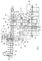
- the mode of operation of the described device is as follows when it is part of the device for producing wire pins, which is partially shown in FIG. 1:
- a feed not shown but known, pulls the wire (154) from the wire supply through a straightening device and pushes it, as shown in FIG. 1 , as much wire through the opened cutting tools (152) and into the tooth gaps of the two toothed belts (92 and 94), only the lower toothed belt (92) being drawn in in FIG. 1, as for the desired wire pin length and for shaping the Wire pin head (84) is required.
- the cutting tools (152) which act against one another and can each sit in a lever or in a carriage, cut off the wire (154), a pyramid-shaped wire pin tip (88) being produced.
- the intermittent drive of the pair of toothed belts (92 and 94) stops briefly. Then the drive is switched on again for a short time, thereby moving the pair of toothed belts one step further and stopping again before a new wire feed (this could also be done by a stepping gear). This happens until a cut-to-length pin blank (86) comes to rest between the clamping tools (76) of the clamping device (78) and in the middle in front of the upsetting tool (54) of the upsetting device (14).
- the compensation is that the cutting tools (152) of the cutting device and the clamping and upsetting device (78, 14) of the device for producing wire pins (82) are arranged in a stationary manner, the different distance from the wire pin tip (88) to the upsetting tool (54) in the manufacture of a different pin length is compensated for by shifting the pin blanks (86) in their longitudinal direction within the transport path between the cutting station and the head upsetting station, as follows: The positioning of the pin blanks (86) is carried out by the two positioning tools (132 and 146) of the positioning device (116), the first tool (132) having its four working surfaces (134 to 140) for a gradual feed.
- the step-by-step positioning takes place with each advance stroke of the slide (12).
- the carriage (12) moves forward, i.e. when each wire pin head (84) is produced
- the positioning tool (132) guided in the machine frame (36) is transferred to the transport device (96) via the connecting rod (110) and the rocker arm (106). Moved so that the pin blank (86) located at the time in front of the first working surface (134) of the positioning tool (132) is advanced by a certain amount.
- the transport device (96) stands still during this process.
- the pin blank (86) is possibly moved back a short distance from the work surface (150), as a result of which the length tolerances of the pin blanks are compensated for so that it has reached its final position, and he comes after the two transport intervals between the clamping tools (76) that exactly such a large wire end protrudes from the clamping jaws (76) as is required to form the wire pin head (84).
- the second positioning tool (146) moves them back in two steps, in such a way that the pin blanks are first moved back from the work surface (148) and then from the work surface (150) to the final position.
- the positioning device (116) can be dispensed with entirely if only pins of a length order are to be produced, or if no such high pin quality is required.
- the cutting device is then arranged so that the pin blanks (86) come to rest in the transport device (96) in such a way that just such a wire end comes out of the Clamping tools (76) protrude as is required for the head production during the upsetting process.
- the clamping jaws (76) close, they hold the pin blank (86) for the following upsetting process to produce the pin head (84).
- the connecting rod (18) is set in motion by the (short-stroke) crank pin (24) of the drive shaft (28), which gives the carriage (12) a reciprocating movement.
- a finished wire pin (82) is moved further out of the tool area, while a new pin blank (86) gets between the tools (54 and 76), whereupon the process begins again.
- the finished pins (82) fall out safely via a slide at the end of the transport route without an additional ejector, or the orderly arriving finished pins can also be automatically removed and removed for magazine or other processing.
- the upsetting tool (54) is arranged in a separate guide (48) and is not positively connected to the slide (12), the upsetting tool (54) together with the guide (48) can be removed as a unit by simply loosening the nuts of the stud bolts ( 66) can be easily removed and replaced if necessary. Furthermore, the clamping tools (76) can be replaced easily accessible after removing this unit. Another advantage of this, book-led outside of the carriage (12) Upsetting tool arrangement is its long circular guide, which extends over a relatively large part of the tool length on both sides, which ensures that the tool is supported without play and canting.
- the upsetting pressure does not have to be absorbed by the slide (12) and its guide strips (32, 34), which would have to be replaced as a whole in the event of excessive wear.
- the inaccuracy of the manufactured product was transferred with increasing wear of the slide and the guide parts, ie with increasing guide play, so that the machine had to be continuously monitored in order not to produce any rejects. As the lead game increased, the machine became louder and louder.
Description
Die Erfindung betrifft eine Staucheinrichtung gemäß Oberbegriff des Anspruchs 1, wie sie aus der US-A-382 632 bekannt war.
Es ist bereits bekannt, die Staucheinrichtung einer Vorrichtung zur Herstellung von Drahtstiften mit Kurzhub des Stauchwerkzeugs auszuführen, wobei das Anstauchen des Drahtstiftkopfes entweder von einer Kurzhub-Kurbelwelle oder von einer Kurzhub-Kurvenscheibe aus über einen Stauchschlitten erfolgen kann. Vorteilhaft hierbei ist, daß für die Verformung eine längere Zeit als bei Langhub-Ausführungen zur Verfügung steht, was eine kleinere Verformungsgeschwindigkeit und einen kleineren Formänderungswiderstand bedeutet. Es entsteht ein weicherer übergang beim Stauchvorgang ohne Wechsel des Betriebsspiels in den Koppelgliedern und somit eine geräuscharme Maschine. Vergleiche Abbildung 1 und 2 der am 24.8.1950 bekanntgemachten bundesdeutschen Patentanmeldung 7e, 10.p 3385D vom 1.10.1948.The invention relates to an upsetting device according to the preamble of claim 1, as was known from US-A-382 632.
It is already known to design the upsetting device of a device for producing wire pins with a short stroke of the upsetting tool, wherein the upsetting of the wire pin head can take place either from a short-stroke crankshaft or from a short-stroke cam disk via a compression sled. The advantage here is that a longer time is available for the deformation than with long-stroke designs, which means a lower deformation speed and a smaller resistance to deformation. The result is a smoother transition during the upsetting process without changing the operating play in the coupling links and thus a low-noise machine. Compare Figures 1 and 2 of the Federal German patent application 7e, 10.p 3385D of October 1, 1948 published on August 24, 1950.
Nachteilig bei der Kurzhubausführung ist jedoch, daß wegen des kurzen Stauchwerkzeugweges der Abstand zwischen den Draht während des Kopf-Anstauchens festhaltenden und als Amboß dienenden Klemmbacken und dem Stauchwerkzeug, wenn sich der Stauchschlitten in zurückgezogener Stellung befindet, sehr gering ist. Müssen nun das Stauchwerkzeug und vor allem die Klemmwerkzeuge bei Werkzeugverschleiß oder bei Änderung des zu verarbeitenden Drahtdurchmessers ausgewechselt werden, ist es bis jetzt erforderlich, den schweren Backenkasten, in dem die Klemmbacken sitzen, als Ganzes auszubauen, um die Werkzeuge wechseln zu können. Vergleiche Abbildung 9(Seite 40) zum Aufsatz von J . Gloser: "Tschechoslowakische Nägelautomaten" auf Seiten 34 bis 43 in der Zeitschrift "Die Schwerindustrie der Tschechoslowakei" 12/1964.A disadvantage of the short stroke version, however, is that because of the short upsetting tool path, the distance between the wire holding the jaws during the upsetting of the head and serving as an anvil and the upsetting tool when the upsetting carriage is in the retracted position is very small. If the upsetting tool and especially the clamping tools have to be replaced when the tool is worn or when the wire diameter to be processed is changed, it has so far been necessary to remove the heavy jaw box in which the clamping jaws are seated in order to remove them To be able to change tools. Compare Figure 9 (page 40) for the essay by J. Gloser: "Czechoslovak Nail Machines" on
Der Erfindung liegt daher die Aufgabe zugrunde, eine Staucheinrichtung in Kurzhubausführung zu schaffen, bei der infolge einer Änderung des zu verarbeitenden Drahtdurchmessers oder bei Werkzeugverschleiß möglichst nur wenige leichte Einrichtungsteile entfernt werden müssen, um die Werkzeuge auswechseln zu können. Ferner soll die Einrichtung präziser, wartungsärmer und noch leiser arbeiten können.
Diese Aufgabe wird ausgehend von einer Einrichtung der eingangs genannten Art erfindungsgemäß durch die kennzeichnenden Merkmale des Anspruchs 1 gelöst. Dadurch kann das Stauchwerkzeug samt Führung zum Durchführen der Umstellarbeiten als Einheit einfach entfernt werden. Durch die getrennte Anordnung von Stauchwerkzeug und Antriebsschlitten ist ferner ein eventuell erforderliches Nacharbeiten der Schlittenführungsteile ohne nachteiligen Einfluß auf den Stauchvorgang, d.h. auf die Produktqualität, möglich.
Weitere Vorteile sind am Beschreibungsende genannt. Diese und jene zuvor genannten Vorteile wurden zwar auch schon mit der Staucheinrichtung gemäß US-A-382 632 erreicht; diese veraltete Einrichtung ist aber eine ungenau und laut arbeitende Stiftpresse mit einer Hub- und Senkvorrichtung (Figur 11) für die Werkzeugführung, die sich abgesenkt über Federn auf dem Maschinengestell abstützt, und mit einem relativ langen Schlittenhub, der nicht nur den Stauchhub, sondern auch noch einen Freihub umfaßt, der nötig ist, um den das Stauchwerkzeug beaufschlagenden Teil des Stauchschlittens an das Stauchwerkzeug heranzufahren, nachdem die Werkzeugführung abgesenkt worden ist. Offenbar kann diese bekannte Staucheinrichtung nicht präzise und leise arbeiten.The invention is therefore based on the object of providing an upsetting device in a short-stroke design in which, as a result of a change in the wire diameter to be processed or in the case of tool wear, as few as possible light device parts have to be removed in order to be able to replace the tools. Furthermore, the facility should be able to work more precisely, with less maintenance and even quieter.
This object is achieved on the basis of a device of the type mentioned in the introduction by the characterizing features of claim 1. As a result, the upsetting tool and guide can be easily removed as a unit for carrying out the conversion work. Due to the separate arrangement of the upsetting tool and the drive slide, any reworking of the slide guide parts that may be required is possible without an adverse influence on the upsetting process, ie on the product quality.
Further advantages are mentioned at the end of the description. These and those advantages mentioned above have already been achieved with the upsetting device according to US-A-382 632; this obsolete device is an inaccurate and noisy working pin press with a lifting and lowering device (Figure 11) for the tool guide, which is supported by springs on the machine frame, and with a relatively long slide stroke, which not only the compression stroke, but also still includes a free stroke, which is necessary in order to move the part of the upset carriage which acts on the upset tool to the upset tool after the tool guide has been lowered. Apparently, this known upsetting device cannot work precisely and quietly.
Gegenstand der Erfindung ist auch die Verwendung der erfindungsgemäßen Stauchvorrichtung in einer drahtverarbeitenden Maschine, insbesondere zur Herstellung von Kopfnägeln.The invention also relates to the use of the upsetting device according to the invention in a wire-processing machine, in particular for the production of headnails.
Im folgenden ist die Erfindung anhand der durch die Zeichnung beispielhaft dargestellten bevorzugten Ausführungsform der erfindungsgemäßen Einrichtung im einzelnen erläutert. Es zeigen:
- Fig. 1
- die Ausführungsform in Draufsicht, in abgebrochener Darstellung
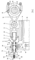
- Fig. 2
- die Ausführungsform in Seitenansicht, geschnitten dargestellt
In axialer Verlängerung der Stellschraube (42) ist in einer separaten Führung (48) in Lagerbuchsen (50 und 52) ein Stauchwerkzeug (54) der Staucheinrichtung (14) längsbeweglich, gleitgelagert geführt, angeordnet. Die Lagerbuchse (50) ist in einen Deckel (58) eingepreßt, der an die Führung (48) angeschraubt ist, während die Buchse (52) direkt in der Führung (48) sitzt. An der Buchse (52) ist an ihrem, in die Führung (48) reichenden Ende ein Absatz angedreht, an dem das eine Ende einer Druckfeder (60) anliegt, deren anderes Ende an einem Anlaufring (62) anliegt, der von einem Bund (56) des Stauchwerkzeugs (54) gehalten wird.
Die Führung (48) mit dem schwimmend gelagerten Stauchwerkzeug (54) ist mittels zweier Stehbolzen (66) leicht abnehm- bzw. austauschbar auf einem, am Maschinengestell (36) befestigten Lagerbock (68), mittels Paßfeder (70) justiert, befestigt. Dank der Rückholfeder (60) liegt das Stauchwerkzeug (54) dauernd kraftschlüssig am Sechskant-Kopf der Stellschraube (42) an.
In Verlängerung der Achse des Stauchwerkzeugs (54) sind in unmittelbarer Nähe vor diesem und symmetrisch zu dieser Achse zwei, in je einem Hebel oder Schlitten sitzende gegeneinanderwirkende Klemmwerkzeuge (76) einer Klemmeinrichtung (78) der Vorrichtung zur Herstellung von Drahtstiften angeordnet. Zwischen den Klemmwerkzeugen (76) befindet sich in Fig. 1 ein Drahtstift (82) mit angestauchtem Kopf (84) fest eingeklemmt, hergestellt aus einem Stiftrohling (86).
Der in Fig. 2 aus den Klemmwerkzeugen (76) herausragende Schaft des Drahtstifts (82) liegt, fest eingeklemmt, in den Zahnlücken zweier Zahnriemen (92 und 94) einer Transporteinrichtung (96) der Vorrichtung zur Herstellung von Drahtstiften, mit der die noch keinen Kopf (84) aufweisenden Stiftrohlinge (86) intermittierend, in horizontaler und vertikaler Ebene exakt mittig vor das Stauchwerkzeug (54) der Staucheinrichtung (14) heran- und von diesem weggeführt werden. Die Zahnriemen (92 und 94) bewegen sich dabei schrittweise quer zur Stauch- und Klemmrichtung der Stauch- und Klemmeinrichtung (14,78). Mittels je einer höhenverstellbaren Führungsschiene (98 bzw. 100) kann der Abstand der Zahnriemen (92 und 94) voneinander, und damit die Spannung, mit der die Stiftrohlinge (86) in den Zahnlücken gehalten werden, eingestellt werden. Durch seitliche Führungsflächen der Führungsschienen (98 und 100) werden die Zahnriemen (92 und 94) ferner, seitlich unverrückbar, über die Transportstrecke geführt, die sich von einer Drahtschneideinrichtung zur Stauch- und Klemmeinrichtung erstreckt.
In Fig. 1 ist am vorderen Teil der Führung des Schlittens (12) ein Lager (102) befestigt, in dem auf einem Bolzen (104) ein Wipp-Hebel (106) gelagert ist. An jedem Arm dieses Hebels (106) greift an einem Bolzen (108) eine Verbindungsstange (110) an, die den Wipphebel (106) einerseits mit dem Schlitten (12) der Staucheinrichtung (14) über einen Bolzen (112) bzw. andererseits mit einem Werkzeug-Halter (114) einer Positioniereinrichtung (116) für die Stiftrohlinge (86) über einen Bolzen (118) koppelt. Die Verbindungsstangen (110) bestehen aus Gelenkköpfen (120 und 122), die durch ein Spannschloß (124) miteinander verbunden sind.
Der Werkzeug-Halter (114) ist mittels zweier untereinandliegender Stangen (126) im Maschinengestell (36) längsbeweglich geführt. Am Halter (114) ist ein Positionierwerkzeug (132) mit vier Arbeitsflächen (134 bis 140) für einen 4-stufigen Positoniervorgang angeordnet, während dessen die Längslage der Stiftrohlinge (86) geändert werden kann.
Am Schlitten (12) ist, in einem Schlitz längseinstellbar, ein zussätzliches Positonierwerkzeug (146) mittels des Bolzens (112), durch den der Gelenkkopf (122) befestigt ist, festgeklemmt. Dieses Positionierwerkzeug (146) ist mit nur zwei Arbeitsflächen (148, 150) zum axialen Verschieben der Stiftrohlinge (86) entgegen der Verschieberichtung des ersten Positonierwerkzeugs (132) versehen.
Ganz links in Fig. 1 ist das untere zweier gegeneinanderwirkender Schneidwerkzeuge (152) der Schneideinrichtung der Vorrichtung zur Herstellung von Drahtstiften zum Ablängen vom Draht (154) und pyramidenförmigen Anspitzen der Drahtstiftrohlinge (86) angedeutet.The invention is explained in detail below with reference to the preferred embodiment of the device according to the invention, which is shown by way of example in the drawing. Show it:
- Fig. 1
- the embodiment in plan view, in a broken view
- Fig. 2
- the embodiment shown in side view, cut
In an axial extension of the adjusting screw (42), an upsetting tool (54) of the upsetting device (14) is arranged in a separate guide (48) in bearing bushings (50 and 52) and is guided in a longitudinally movable manner, with sliding bearings. The bearing bush (50) is pressed into a cover (58) which is screwed onto the guide (48), while the bush (52) sits directly in the guide (48). A shoulder is screwed to the socket (52) at its end reaching into the guide (48), on which one end of a compression spring (60) rests, the other end of which rests on a thrust ring (62) which is supported by a collar ( 56) of the upsetting tool (54) is held.
The guide (48) with the floating upset tool (54) can be easily removed or replaced by means of two stud bolts (66) on a bearing block (68) attached to the machine frame (36), adjusted by means of a key (70). Thanks to the return spring (60), the compression tool (54) is permanently non-positively against the hexagon head of the adjusting screw (42).
In the extension of the axis of the upsetting tool (54), two clamping tools (76) of a clamping device (78) of the device for producing wire pins, which act against one another in a lever or slide, are arranged in the immediate vicinity in front of this and symmetrically to this axis. In FIG. 1, a wire pin (82) with an upset head (84) is firmly clamped between the clamping tools (76), made from a pin blank (86).
The shaft of the wire pin (82) protruding from the clamping tools (76) in FIG. 2 lies, firmly clamped, in the tooth gaps of two toothed belts (92 and 94) of a transport device (96) of the device for producing wire pins, with which none Head (84) having pin blanks (86) intermittently, in the horizontal and vertical plane exactly in front of the upsetting tool (54) of the upsetting device (14) and guided away from it. The toothed belts (92 and 94) move stepwise transversely to the compression and clamping direction of the compression and clamping device (14, 78). The spacing of the toothed belts (92 and 94) from one another, and thus the tension with which the pin blanks (86) are held in the tooth gaps, can be set by means of a height-adjustable guide rail (98 or 100). Through lateral guide surfaces of the guide rails (98 and 100), the toothed belts (92 and 94) are also guided laterally immovably over the transport route which extends from a wire cutting device to the upsetting and clamping device.
In Fig. 1, a bearing (102) is attached to the front part of the guide of the carriage (12), in which a rocker arm (106) is mounted on a bolt (104). On each arm of this lever (106) a connecting rod (110) engages on a bolt (108), which connects the rocker arm (106) on the one hand to the slide (12) of the upsetting device (14) via a bolt (112) or on the other hand couples a tool holder (114) to a positioning device (116) for the pin blanks (86) via a bolt (118). The connecting rods (110) consist of rod ends (120 and 122) which are connected to each other by a turnbuckle (124).
The tool holder (114) is by means of two rods (126) lying one below the other guided longitudinally in the machine frame (36). A positioning tool (132) with four working surfaces (134 to 140) for a 4-stage positioning process is arranged on the holder (114), during which the longitudinal position of the pin blanks (86) can be changed.
An additional positioning tool (146) is clamped to the slide (12) in a slot, by means of the bolt (112), through which the joint head (122) is fastened. This positioning tool (146) is provided with only two working surfaces (148, 150) for axially displacing the pin blanks (86) against the direction of displacement of the first positioning tool (132).
On the far left in FIG. 1, the lower of two counter-cutting tools (152) of the cutting device of the device for producing wire pins for cutting to length from the wire (154) and pyramid-shaped sharpening of the wire pin blanks (86) is indicated.
Die Wirkungsweise der beschriebenen Einrichtung ist folgende, wenn sie Teil der in Fig. 1 teilweise gezeigten Vorrichtung zur Herstellung von Drahtstiften ist: Ein nicht dargestellter, aber bekannter Einzug zieht den Draht (154) vom Drahtvorrat durch einen Richtapparat und schiebt, gemäß Fig. 1, soviel Draht durch die geöffneten Schneidwerkzeuge (152) hindurch und in die Zahnlücken der beiden Zahnriemen (92 und 94), wobei in Fig. 1 nur der untere Zahnriemen (92) eingezeichnet ist, hinein, wie für die gewünschte Drahtstiftlänge und zur Formung des Drahtstiftkopfes (84) benötigt wird. Nun schneiden die gegeneinanderwirkenden Schneidwerkzeuge (152), die in je einem Hebel oder in je einem Schlitten sitzen können, den Draht (154) ab, wobei eine pyramidenförmige Drahtstiftspitze (88) entsteht. Während des Einschiebens zwischen die beiden Zahnriemen (92 und 94) und Abschneidens des Drahtes (154) steht der intermittierende Antrieb des Zahnriemenpaars (92 und 94) kurzzeitig still. Danach wird der Antrieb für kurze Zeit wieder eingeschaltet und das Zahnriemenpaar dadurch einen Schritt weiterbewegt, und vor einem erneuten Drahtvorschub wieder gestoppt (dies könnte auch durch ein Schrittschaltgetriebe erfolgen). Das geschieht so oft, bis ein abgelängter Stiftrohling (86) zwischen den Klemmwerkzeugen (76) der Klemmeinrichtung (78) und mittig vor dem Stauchwerkzeug (54) der Staucheinrichtung (14) zu liegen kommt. Um mit der Vorrichtung Stifte in einem möglichst großen Längenbereich ohne größere Umstellarbeiten herstellen zu können, wird zum Ausgleich dafür, daß die Schneidwerkzeuge (152) der Schneideinrichtung sowie die Klemm- und Staucheinrichtung (78,14) der Vorrichtung zur Herstellung von Drahtstiften (82) stationär angeordnet sind, der unterschiedliche Abstand von der Drahtstiftspitze (88) bis zum Stauchwerkzeug (54) bei der Fertigung einer anderen Stiftlänge durch Verschieben der Stiftrohlinge (86) in ihrer Längsrichtung innerhalb der Transportstrecke zwischen Schneidstation und Kopfanstauchstation ausgeglichen, und zwar folgendermaßen:
Das Positonieren der Stiftrohlinge (86) erfolgt durch die beiden Positonierwerkzeuge (132 und 146) der Positioniereinrichtung (116), wobei das erste Werkzeug (132) seine vier Arbeitsflächen (134 bis 140) für einen schrittweisen Vorschub aufweist. Das schrittweise Positionieren erfolgt bei jedem Vorhub des Schlittens (12). Bei der Vorwärtsbewegung des Schlittens (12), also beim Erzeugen eines jeden Drahtstiftkopfes (84), wird das im Maschinengestell (36) geführte Positionierwerkzeug (132) über die Verbindungsstange (110) und den Wipp-Hebel (106) zur Transporteinrichtung (96) hin bewegt, so daß der zu diesem Zeitpunkt vor der ersten Arbeitsfläche (134) des Positonierwerkzeugs (132) befindliche Stiftrohling (86) um einen bestimmten Betrag vorgeschoben wird. Wie bereits erwähnt, steht bei diesem Vorgang die Transporteinrichtung (96) still. Während der Schlitten (12) zurückläuft, wird der Antrieb kurzzeitig für ein Transportintervall betätigt, so daß der zuvor von der Arbeitsfläche (134) des Werkzeugs (132) vorbewegte Stiftrohling (86) sich nun vor der zweiten Arbeitsfläche (136) befindet und bei einem erneuten Stauchvorgang um das gleiche Maß vorgeschoben wird. Das geschieht so oft, bis der Stiftrohling (86) von der vierten Arbeitsfläche (140) des Positionierwerkzeugs (132) in seine vorderste Lage verschoben wurde. In dieser Längslage wird der Stiftrohling (86) schrittweise in Richtung Stauchstation weitertransportiert, bis er vor der Arbeitsfläche (150) des zweiten Positionierwerkzeugs (146) zu liegen kommt. Ebenfalls von der Stauchbewegung des Schlittens (12) aus abgeleitet, wird der Stiftrohling (86) von der Arbeitsfläche (150) ggf. ein kurzes Stück zurückbewegt, wodurch die Längentoleranzen der Stiftrohlinge ausgeglichen werden, so daß er seine endgültige Lage eingenommen hat, und er kommt im Ausführungsbeispiel nach zwei Transportintervallen so zwischen den Klemmwerkzeugen (76) zu liegen, daß genau ein so großes Drahtende aus den Klemmbacken (76) herausragt, wie zur Formung des Drahtstiftkopfes (84) benötigt wird. Bei längeren Stiftrohlingen (86) erfolgt deren Zurückbewegung durch das zweite Positionierwerkzeug (146) in zwei Schritten, und zwar derart, daß die Stiftrohlinge zuerst von der Arbeitsfläche (148) und daran anschließend von der Arbeitsfläche (150) in die endgültige Lage zurückbewegt werden.The mode of operation of the described device is as follows when it is part of the device for producing wire pins, which is partially shown in FIG. 1: A feed, not shown but known, pulls the wire (154) from the wire supply through a straightening device and pushes it, as shown in FIG. 1 , as much wire through the opened cutting tools (152) and into the tooth gaps of the two toothed belts (92 and 94), only the lower toothed belt (92) being drawn in in FIG. 1, as for the desired wire pin length and for shaping the Wire pin head (84) is required. Now the cutting tools (152), which act against one another and can each sit in a lever or in a carriage, cut off the wire (154), a pyramid-shaped wire pin tip (88) being produced. During the insertion between the two toothed belts (92 and 94) and the cutting of the wire (154), the intermittent drive of the pair of toothed belts (92 and 94) stops briefly. Then the drive is switched on again for a short time, thereby moving the pair of toothed belts one step further and stopping again before a new wire feed (this could also be done by a stepping gear). This happens until a cut-to-length pin blank (86) comes to rest between the clamping tools (76) of the clamping device (78) and in the middle in front of the upsetting tool (54) of the upsetting device (14). In order to be able to produce pins in the greatest possible length range with the device without major conversion work, the compensation is that the cutting tools (152) of the cutting device and the clamping and upsetting device (78, 14) of the device for producing wire pins (82) are arranged in a stationary manner, the different distance from the wire pin tip (88) to the upsetting tool (54) in the manufacture of a different pin length is compensated for by shifting the pin blanks (86) in their longitudinal direction within the transport path between the cutting station and the head upsetting station, as follows:
The positioning of the pin blanks (86) is carried out by the two positioning tools (132 and 146) of the positioning device (116), the first tool (132) having its four working surfaces (134 to 140) for a gradual feed. The step-by-step positioning takes place with each advance stroke of the slide (12). When the carriage (12) moves forward, i.e. when each wire pin head (84) is produced, the positioning tool (132) guided in the machine frame (36) is transferred to the transport device (96) via the connecting rod (110) and the rocker arm (106). Moved so that the pin blank (86) located at the time in front of the first working surface (134) of the positioning tool (132) is advanced by a certain amount. As already mentioned, the transport device (96) stands still during this process. While the carriage (12) is running back, the drive is actuated briefly for a transport interval, so that the pin blank (86) previously moved from the working surface (134) of the tool (132) is now in front of the second working surface (136) and at one renewed upsetting is advanced by the same amount. This happens until the pin blank (86) has been moved from the fourth working surface (140) of the positioning tool (132) to its foremost position. In this longitudinal position, the pin blank (86) is gradually transported in the direction of the upsetting station until it comes to rest in front of the working surface (150) of the second positioning tool (146). Also derived from the compression movement of the carriage (12), the pin blank (86) is possibly moved back a short distance from the work surface (150), as a result of which the length tolerances of the pin blanks are compensated for so that it has reached its final position, and he comes after the two transport intervals between the clamping tools (76) that exactly such a large wire end protrudes from the clamping jaws (76) as is required to form the wire pin head (84). In the case of longer pin blanks (86), the second positioning tool (146) moves them back in two steps, in such a way that the pin blanks are first moved back from the work surface (148) and then from the work surface (150) to the final position.
Es ist offensichtlich, daß auf die Positioniereinrichtung (116) gänzlich verzichtet werden kann, wenn nur Stifte einer Längenordnung gefertigt werden sollen, oder aber, wenn keine so hohe Stiftqualität verlangt wird. Die Schneideinrichtung wird dann so angeordnet, daß die Stiftrohlinge (86) so in der Transporteinrichtung (96) zu liegen kommen, daß gerade ein solches Drahtende aus den Klemmwerkzeugen (76) herausragt, wie für die Kopferzeugung beim Stauchvorgang benötigt wird.
Schließen die Klemmbacken (76), dann halten sie den Stiftrohling (86) für den nun folgenden Stauchvorgang zum Erzeugen des Stiftkopfes (84) fest. Hierzu wird die Pleuelstange (18) vom (Kurzhub-) Kurbelzapfen (24) der Antriebswelle (28) in Bewegung gesetzt, die dem Schlitten (12) eine hin- und hergehende Bewegung verleiht. Diese hin- und hergehende Bewegung macht das, durch die Rückholfeder (60) nicht formschlüssig mit dem Sechskant der Stellschraube (46) verbundene Stauchwerkzeug (54) mit, und erzeugt bei jeder Vorwärtsbewegung einen Kopf (84) an dem Stiftrohling (86), wobei die Klemmwerkzeuge (76) als Amboß dienen. Bei jeder Rückwärtsbewegung des Schlittens (12) entspannt sich die Druckfeder (60) und sie drückt das Stauchwerkzeug (54) über den Anlaufring (62) am Bund (56) des Stauchwerkzeugs (54) zurück, so daß dieses in dauernder kraftschlüssiger Anlage an der Stellschraube (42) verbleibt. Die Höhe des Stauchdruckes (und damit auch die Form des Drahtstiftkopfes) kann mittels der Stellschraube (42) durch mehr oder weniger weites Eindrehen derselben in den Gewindeflansch (40) am Schlitten (12) eingestellt werden.
Bei jedem Transportschritt wird ein fertiger Drahtstift (82) aus dem Werkzeugbereich heraus weiter bewegt, während ein neuer Stiftrohling (86) zwischen die Werkzeuge (54 und 76) gelangt, worauf der Vorgang von neuem beginnt. Nach einigen Transportintervallen fallen die fertigen Stifte (82) am Ende der Transportstrecke ohne zusätzlichen Ausstoßer über eine Rutsche sicher aus, oder es können die geordnet ankommenden fertigen Stifte zur Magazinierung oder sonstigen Weiterverarbeitung auch einzeln automatisch entnommen und abgeführt werden.It is obvious that the positioning device (116) can be dispensed with entirely if only pins of a length order are to be produced, or if no such high pin quality is required. The cutting device is then arranged so that the pin blanks (86) come to rest in the transport device (96) in such a way that just such a wire end comes out of the Clamping tools (76) protrude as is required for the head production during the upsetting process.
When the clamping jaws (76) close, they hold the pin blank (86) for the following upsetting process to produce the pin head (84). For this purpose, the connecting rod (18) is set in motion by the (short-stroke) crank pin (24) of the drive shaft (28), which gives the carriage (12) a reciprocating movement. This reciprocating movement does this with the upset tool (54) which is not positively connected to the hexagon of the adjusting screw (46) by the return spring (60), and generates a head (84) on the pin blank (86) with each forward movement, whereby the clamping tools (76) serve as an anvil. With each backward movement of the carriage (12), the compression spring (60) relaxes and it presses the upsetting tool (54) over the thrust ring (62) on the collar (56) of the upsetting tool (54), so that this is in permanent non-positive contact with the Set screw (42) remains. The height of the upsetting pressure (and thus also the shape of the wire pin head) can be adjusted by means of the adjusting screw (42) by screwing it more or less far into the threaded flange (40) on the slide (12).
With each transport step, a finished wire pin (82) is moved further out of the tool area, while a new pin blank (86) gets between the tools (54 and 76), whereupon the process begins again. After a few transport intervals, the finished pins (82) fall out safely via a slide at the end of the transport route without an additional ejector, or the orderly arriving finished pins can also be automatically removed and removed for magazine or other processing.
Dadurch, daß das Stauchwerkzeug (54) in einer separaten Führung (48) angeordnet ist und nicht mit dem Schlitten (12) formschlüssig verbunden ist, können das Stauchwerkzeug (54) samt Führung (48) als Einheit durch einfaches Lösen der Muttern der Stehbolzen (66) leicht abgenommen und ggf. ausgetauscht werden. Ferner können die Klemmwerkzeuge (76) nach Entfernen dieser Einheit leicht zugänglich ausgewechselt werden.
Ein weiterer Vorteil dieser, außerhalb des Schlittens (12) buchsgeführten Stauchwerkzeuganordnung ist deren lange Rundführung, die sich über einen relativ großen Teil der Werkzeuglänge beidseitig erstreckt, wodurch für eine spielfreie und verkantungsfreie Lagerung des Werkzeugs gesorgt ist.
Ferner muß der Stauchdruck nicht wie bisher vom Schlitten (12) und von dessen Führungsleisten (32, 34) aufgenommen werden, die bei zu großem Verschleiß als Ganzes ausgewechselt werden müssten. Bei der bekannten, nicht getrennten Anordnung von Schlitten und Stauchwerkzeug, übertrug sich bei zunehmendem Verschleiß des Schlittens und der Führungsteile, d.h. bei größer werdendem Führungsspiel die Ungenauigkeit auf das hergestellte Produkt, so daß die Maschine dauernd überwacht werden mußte, um keinen Ausschuß zu produzieren. Mit zunehmendem Führungsspiel wurde die Maschine immer lauter.Because the upsetting tool (54) is arranged in a separate guide (48) and is not positively connected to the slide (12), the upsetting tool (54) together with the guide (48) can be removed as a unit by simply loosening the nuts of the stud bolts ( 66) can be easily removed and replaced if necessary. Furthermore, the clamping tools (76) can be replaced easily accessible after removing this unit.
Another advantage of this, book-led outside of the carriage (12) Upsetting tool arrangement is its long circular guide, which extends over a relatively large part of the tool length on both sides, which ensures that the tool is supported without play and canting.
Furthermore, the upsetting pressure does not have to be absorbed by the slide (12) and its guide strips (32, 34), which would have to be replaced as a whole in the event of excessive wear. In the known, not separate arrangement of slide and upsetting tool, the inaccuracy of the manufactured product was transferred with increasing wear of the slide and the guide parts, ie with increasing guide play, so that the machine had to be continuously monitored in order not to produce any rejects. As the lead game increased, the machine became louder and louder.
Claims (9)
- Upsetting equipment, for the upsetting of the one end of elongate workpieces (86) such as pieces of wire, in particular for the production of heads at nails, with an upsetting carriage (12), which is movable to and fro at a carriage guide (34) and provided with a setting member (42) for varying the length of the upsetting carriage (12), and with an upsetting tool (54) separate from the upsetting carriage (12) and with its own longitudinal guide (48/52, 58/50) parallel to the carriage guide (34), wherein the upsetting tool (54) is acted on in forward direction by a part (42) of the upsetting carriage (12) and in rearward direction by a helical compression spring (60), which bears at the rear against an outer part (56) of the upsetting tool (54) and at the front against a bearing housing (48, 58) of the longitudinal guide (48/52, 58/50) of the upsetting tool (54), characterised thereby, that the cylindrical upsetting tool (54) is provided with an external collar (56) as outer part and arranged under the restoring force of the biassed helical compression spring (60), which receives the upsetting tool (54) and bears against the external collar (56) as well as in the bearing housing (48, 58), which is constructed as spring housing and against which the setting member (42) permanently lies force-lockingly as that part of the upsetting carriage (12) executing short strokes, which acts on the upsetting tool (54), and that the elongate workpieces (86) can be conducted transversely to the upsetting direction to in front of and away from the upsetting tool (54) by means of a transport equipment (96).
- Upsetting equipment according to claim 1, characterised thereby, that the bearing housing (48, 58) comprises two colinear bearing bushes (50 and 52) for the circular guidance of the round upsetting tool (54).
- Upsetting equipment according to claim 1 or 2, characterised thereby, that the bearing housing (48, 58) is detachably fastened at a stationary bearing block (68) adjusted by means of a fitting key (70).
- Upsetting equipment according to one of the claims 1 to 3, characterised thereby, that the setting member is constructed as a headed screw (42).
- Upsetting equipment according to one of the claims 1 to 4, characterised by an additional positioning equipment (116) for arranging the workpieces (86), which are clamped fast by means of two transport belts (92 and 94), along their axis, with at least one in itself rigid positioning tool (132) for displacing at least one workpiece (86) through a predetermined distance in its longitudinal direction, wherein the positioning tool (132) has at least one operative surface (134 or 136 or 138 or 140), which is movable parallelly to the longitudinal direction of the workpieces (86) and which during its working stroke acts on and entrains a workpiece lying in its path.
- Upsetting equipment according to claim 5, characterised thereby, that the positioning tool (132) and the upsetting carriage (12) are coupled for a rectilinear movement in the same direction and opposite sense by means of two link rods (120, 122, 124) and a two-armed lever (106), which is arranged to be rotatable at a bearing (102) firmly connected with the carriage guide (32, 34).
- Upsetting equipment according to claim 6, characterised thereby, that a respective tensioning shackle (124) with joint bearings (120 and 122) at the ends is provided as each link rod (120, 122, 124).
- Upsetting equipment according to one of the claims 5 to 7, characterised thereby, that a positioning tool (146) is fastened at the upsetting carriage (12) to be adjustable in its stroke direction.
- Use of an upsetting equipment according to one of the claims 1 to 8 in a wire-processing machine, in particular a device for the manufacture of treated wire pins, in particular headed nails.
Applications Claiming Priority (2)
| Application Number | Priority Date | Filing Date | Title |
|---|---|---|---|
| DE3922531A DE3922531C1 (en) | 1989-07-08 | 1989-07-08 | |
| DE3922531 | 1989-07-08 |
Publications (2)
| Publication Number | Publication Date |
|---|---|
| EP0407657A1 EP0407657A1 (en) | 1991-01-16 |
| EP0407657B1 true EP0407657B1 (en) | 1994-01-12 |
Family
ID=6384594
Family Applications (1)
| Application Number | Title | Priority Date | Filing Date |
|---|---|---|---|
| EP89121114A Expired - Lifetime EP0407657B1 (en) | 1989-07-08 | 1989-11-15 | Compression device for compressing the ends of elongated workpieces such as pieces of wire and application of such a device in a wire-working machine for manufacturing pins |
Country Status (6)
| Country | Link |
|---|---|
| US (1) | US5088312A (en) |
| EP (1) | EP0407657B1 (en) |
| JP (1) | JPH0712511B2 (en) |
| KR (1) | KR920009832B1 (en) |
| DE (2) | DE3922531C1 (en) |
| ES (1) | ES2048814T3 (en) |
Families Citing this family (4)
| Publication number | Priority date | Publication date | Assignee | Title |
|---|---|---|---|---|
| DE4213228C1 (en) * | 1992-04-22 | 1993-05-13 | Friedhelm Post Sondermaschinen, 7880 Bad Saeckingen, De | |
| US5371338A (en) * | 1992-09-25 | 1994-12-06 | United States Surgical Corporation | Needle blank feeding apparatus |
| CN109217075B (en) * | 2017-07-04 | 2020-07-28 | 泰科电子(上海)有限公司 | Wire processing apparatus |
| CN110038987B (en) * | 2019-05-15 | 2024-03-26 | 邹建明 | Cold header die for hook nail processing and forming and method thereof |
Family Cites Families (16)
| Publication number | Priority date | Publication date | Assignee | Title |
|---|---|---|---|---|
| DE7103385U (en) * | 1971-05-06 | Rilco Maschinenfabrik Gmbh & Co Kg | Ruttelmaschme for soil compaction | |
| US122385A (en) * | 1872-01-02 | Improvement in machines for heading bolts | ||
| US382632A (en) * | 1888-05-08 | Chusetts | ||
| DE49164C (en) * | E. fontaine in Auburndale, Ohio, V. St. A | Method and machine for producing wire nails | ||
| US1109856A (en) * | 1911-04-06 | 1914-09-08 | Walker W Mccarroll | Machine for rectifying electrotypes. |
| US1112544A (en) * | 1911-07-25 | 1914-10-06 | Walker W Mccarroll | Machine for rectifying electrotypes. |
| US1146957A (en) * | 1913-07-01 | 1915-07-20 | Atlas Tack Company | Heading device. |
| US2595433A (en) * | 1947-06-18 | 1952-05-06 | Waterbury Farrel Foundry & Mac | Shaft driving mechanism for headers or like machines |
| CA651104A (en) * | 1959-07-13 | 1962-10-23 | Westinghouse Electric Corporation | Workpiece position control apparatus |
| US3301033A (en) * | 1964-08-14 | 1967-01-31 | Emporium Specialties Co Inc | Apparatus for producing headed wire forms |
| US3514992A (en) * | 1967-11-29 | 1970-06-02 | Braun Eng Co | Cold header |
| US3588933A (en) * | 1968-06-19 | 1971-06-29 | George J Shinopulos | Method and apparatus for simultaneously upset forming both ends of a ductile material rod blank or the like |
| SU742013A1 (en) * | 1975-11-24 | 1980-06-25 | Центральное проектно-конструкторское бюро кузнечно-прессового машиностроения | Nails producing automatic machine |
| US4270651A (en) * | 1979-01-17 | 1981-06-02 | Universal Instruments Corporation | Taped belt electronic component centering device |
| US4737227A (en) * | 1986-02-27 | 1988-04-12 | Universal Instruments Corporation | Axial leaded component centering device and method of centering components |
| US4779444A (en) * | 1987-03-12 | 1988-10-25 | The National Machinery Company | Closed die forging machine |
-
1989
- 1989-07-08 DE DE3922531A patent/DE3922531C1/de not_active Expired - Lifetime
- 1989-11-15 ES ES89121114T patent/ES2048814T3/en not_active Expired - Lifetime
- 1989-11-15 EP EP89121114A patent/EP0407657B1/en not_active Expired - Lifetime
- 1989-11-15 DE DE89121114T patent/DE58906717D1/en not_active Expired - Fee Related
-
1990
- 1990-03-06 JP JP2052908A patent/JPH0712511B2/en not_active Expired - Lifetime
- 1990-06-08 US US07/535,059 patent/US5088312A/en not_active Expired - Fee Related
- 1990-07-09 KR KR1019900010484A patent/KR920009832B1/en not_active IP Right Cessation
Also Published As
| Publication number | Publication date |
|---|---|
| JPH0712511B2 (en) | 1995-02-15 |
| DE3922531C1 (en) | 1990-10-31 |
| EP0407657A1 (en) | 1991-01-16 |
| KR920009832B1 (en) | 1992-10-31 |
| JPH0352734A (en) | 1991-03-06 |
| KR910002534A (en) | 1991-02-25 |
| US5088312A (en) | 1992-02-18 |
| ES2048814T3 (en) | 1994-04-01 |
| DE58906717D1 (en) | 1994-02-24 |
Similar Documents
| Publication | Publication Date | Title |
|---|---|---|
| DE3152593C2 (en) | Device for holding a workpiece in a cutting machine | |
| DE3931320C1 (en) | ||
| DE7718218U1 (en) | CUTTING TOOL SET FOR CUTTING LONGITUDINAL WORKPIECES | |
| DE3634529C2 (en) | Device for conveying, positioning and locking workpieces in a group processing machine | |
| DE2039697C3 (en) | Multi-stage molding machine, especially multi-stage press | |
| DE2728647A1 (en) | MOLDING PRESS | |
| EP0407657B1 (en) | Compression device for compressing the ends of elongated workpieces such as pieces of wire and application of such a device in a wire-working machine for manufacturing pins | |
| DE3517637A1 (en) | ADVANCED SHAPER WITH REMOVABLE TOOL EQUIPMENT | |
| EP3569354A1 (en) | Device for fixing workpieces and processing unit | |
| EP0407655B1 (en) | Positioning device for arranging elongated workpieces and application of such a device in a wire-working machine for manufacturing pins | |
| EP0407656B1 (en) | Transfer device for transferring elongated workpieces such as pieces of wire and the application of such a device in a wire-working machine for manufacturing pins | |
| DE10063154B4 (en) | Forging press with adjusting device on the die side | |
| DE3922532C1 (en) | ||
| DE879192C (en) | Deburring machine | |
| DE436289C (en) | Forging machine for the production of nails, rivets, bolts and similar workpieces | |
| DE416640C (en) | Machine for grooving bolt heads by means of several matrices with different clear widths | |
| DE596999C (en) | Self-acting multiple printing press, especially double printing press | |
| DE1225470B (en) | Stud upsetting press with extrusion and upsetting tools | |
| DE166111C (en) | ||
| DE421181C (en) | Process for the production of studs, headless rivets and similar workpieces with offset shafts | |
| DE2456762A1 (en) | High speed cold rotary machining of screw heads - has shaft cutter which sections rough wire and pushes piece into cutting station | |
| AT219382B (en) | Press | |
| DE3745091C2 (en) | Stamping press tool unit | |
| DE2903276A1 (en) | Two=stroke press for bolt cold heading - has single swivelling die with central channel for bolt blank | |
| DE19959798A1 (en) | Fabrication method for pipe clamp from flat material uses reciprocating piston with piston head having two parallel projections, and anvil with bending edge |
Legal Events
| Date | Code | Title | Description |
|---|---|---|---|
| PUAI | Public reference made under article 153(3) epc to a published international application that has entered the european phase |
Free format text: ORIGINAL CODE: 0009012 |
|
| AK | Designated contracting states |
Kind code of ref document: A1 Designated state(s): DE ES GB IT |
|
| 17P | Request for examination filed |
Effective date: 19901217 |
|
| 17Q | First examination report despatched |
Effective date: 19920416 |
|
| GRAA | (expected) grant |
Free format text: ORIGINAL CODE: 0009210 |
|
| AK | Designated contracting states |
Kind code of ref document: B1 Designated state(s): DE ES GB IT |
|
| GBT | Gb: translation of ep patent filed (gb section 77(6)(a)/1977) |
Effective date: 19940117 |
|
| REF | Corresponds to: |
Ref document number: 58906717 Country of ref document: DE Date of ref document: 19940224 |
|
| ITF | It: translation for a ep patent filed |
Owner name: BARZANO' E ZANARDO MILANO S.P.A. |
|
| REG | Reference to a national code |
Ref country code: ES Ref legal event code: FG2A Ref document number: 2048814 Country of ref document: ES Kind code of ref document: T3 |
|
| PLBE | No opposition filed within time limit |
Free format text: ORIGINAL CODE: 0009261 |
|
| STAA | Information on the status of an ep patent application or granted ep patent |
Free format text: STATUS: NO OPPOSITION FILED WITHIN TIME LIMIT |
|
| 26N | No opposition filed | ||
| PGFP | Annual fee paid to national office [announced via postgrant information from national office to epo] |
Ref country code: GB Payment date: 20011109 Year of fee payment: 13 |
|
| PGFP | Annual fee paid to national office [announced via postgrant information from national office to epo] |
Ref country code: ES Payment date: 20011113 Year of fee payment: 13 |
|
| PGFP | Annual fee paid to national office [announced via postgrant information from national office to epo] |
Ref country code: DE Payment date: 20011128 Year of fee payment: 13 |
|
| REG | Reference to a national code |
Ref country code: GB Ref legal event code: IF02 |
|
| PG25 | Lapsed in a contracting state [announced via postgrant information from national office to epo] |
Ref country code: GB Free format text: LAPSE BECAUSE OF NON-PAYMENT OF DUE FEES Effective date: 20021115 |
|
| PG25 | Lapsed in a contracting state [announced via postgrant information from national office to epo] |
Ref country code: ES Free format text: LAPSE BECAUSE OF NON-PAYMENT OF DUE FEES Effective date: 20021116 |
|
| PG25 | Lapsed in a contracting state [announced via postgrant information from national office to epo] |
Ref country code: DE Free format text: LAPSE BECAUSE OF NON-PAYMENT OF DUE FEES Effective date: 20030603 |
|
| GBPC | Gb: european patent ceased through non-payment of renewal fee | ||
| REG | Reference to a national code |
Ref country code: ES Ref legal event code: FD2A Effective date: 20031213 |
|
| PG25 | Lapsed in a contracting state [announced via postgrant information from national office to epo] |
Ref country code: IT Free format text: LAPSE BECAUSE OF NON-PAYMENT OF DUE FEES;WARNING: LAPSES OF ITALIAN PATENTS WITH EFFECTIVE DATE BEFORE 2007 MAY HAVE OCCURRED AT ANY TIME BEFORE 2007. THE CORRECT EFFECTIVE DATE MAY BE DIFFERENT FROM THE ONE RECORDED. Effective date: 20051115 |