EP0407494B1 - Auslasspumpe - Google Patents
Auslasspumpe Download PDFInfo
- Publication number
- EP0407494B1 EP0407494B1 EP89911677A EP89911677A EP0407494B1 EP 0407494 B1 EP0407494 B1 EP 0407494B1 EP 89911677 A EP89911677 A EP 89911677A EP 89911677 A EP89911677 A EP 89911677A EP 0407494 B1 EP0407494 B1 EP 0407494B1
- Authority
- EP
- European Patent Office
- Prior art keywords
- piston
- seat
- pump
- valve
- container
- Prior art date
- Legal status (The legal status is an assumption and is not a legal conclusion. Google has not performed a legal analysis and makes no representation as to the accuracy of the status listed.)
- Expired - Lifetime
Links
Images


Classifications
-
- B—PERFORMING OPERATIONS; TRANSPORTING
- B05—SPRAYING OR ATOMISING IN GENERAL; APPLYING FLUENT MATERIALS TO SURFACES, IN GENERAL
- B05B—SPRAYING APPARATUS; ATOMISING APPARATUS; NOZZLES
- B05B11/00—Single-unit hand-held apparatus in which flow of contents is produced by the muscular force of the operator at the moment of use
- B05B11/01—Single-unit hand-held apparatus in which flow of contents is produced by the muscular force of the operator at the moment of use characterised by the means producing the flow
- B05B11/10—Pump arrangements for transferring the contents from the container to a pump chamber by a sucking effect and forcing the contents out through the dispensing nozzle
- B05B11/1001—Piston pumps
-
- B—PERFORMING OPERATIONS; TRANSPORTING
- B05—SPRAYING OR ATOMISING IN GENERAL; APPLYING FLUENT MATERIALS TO SURFACES, IN GENERAL
- B05B—SPRAYING APPARATUS; ATOMISING APPARATUS; NOZZLES
- B05B11/00—Single-unit hand-held apparatus in which flow of contents is produced by the muscular force of the operator at the moment of use
- B05B11/01—Single-unit hand-held apparatus in which flow of contents is produced by the muscular force of the operator at the moment of use characterised by the means producing the flow
- B05B11/10—Pump arrangements for transferring the contents from the container to a pump chamber by a sucking effect and forcing the contents out through the dispensing nozzle
- B05B11/1042—Components or details
- B05B11/1059—Means for locking a pump or its actuation means in a fixed position
- B05B11/106—Means for locking a pump or its actuation means in a fixed position in a retracted position, e.g. in an end-of-dispensing-stroke position
-
- B—PERFORMING OPERATIONS; TRANSPORTING
- B05—SPRAYING OR ATOMISING IN GENERAL; APPLYING FLUENT MATERIALS TO SURFACES, IN GENERAL
- B05B—SPRAYING APPARATUS; ATOMISING APPARATUS; NOZZLES
- B05B11/00—Single-unit hand-held apparatus in which flow of contents is produced by the muscular force of the operator at the moment of use
- B05B11/01—Single-unit hand-held apparatus in which flow of contents is produced by the muscular force of the operator at the moment of use characterised by the means producing the flow
- B05B11/10—Pump arrangements for transferring the contents from the container to a pump chamber by a sucking effect and forcing the contents out through the dispensing nozzle
- B05B11/1042—Components or details
- B05B11/1066—Pump inlet valves
- B05B11/1067—Pump inlet valves actuated by pressure
-
- B—PERFORMING OPERATIONS; TRANSPORTING
- B05—SPRAYING OR ATOMISING IN GENERAL; APPLYING FLUENT MATERIALS TO SURFACES, IN GENERAL
- B05B—SPRAYING APPARATUS; ATOMISING APPARATUS; NOZZLES
- B05B11/00—Single-unit hand-held apparatus in which flow of contents is produced by the muscular force of the operator at the moment of use
- B05B11/01—Single-unit hand-held apparatus in which flow of contents is produced by the muscular force of the operator at the moment of use characterised by the means producing the flow
- B05B11/10—Pump arrangements for transferring the contents from the container to a pump chamber by a sucking effect and forcing the contents out through the dispensing nozzle
- B05B11/1097—Pump arrangements for transferring the contents from the container to a pump chamber by a sucking effect and forcing the contents out through the dispensing nozzle with means for sucking back the liquid or other fluent material in the nozzle after a dispensing stroke
Definitions
- the present invention relates to manually operated reciprocating pumps for dispensing liquids from a container.
- a conventional throttling pump for dispensing liquids from a container includes a hollow body having opening in each end, into the upper end of which is fitted a hollow piston which is slidable reciprocally in the body with sealing fit, which piston is connected at its upper end to an actuator.
- the piston and body define an interior chamber having an opening at each end.
- the upper opening of the piston connects with a nozzle of the actuator from which the liquid is dispensed.
- An outlet valve is located in the upper opening and may be a ball-type valve.
- An inlet ball-type valve is located in the lower opening in the lower end portion of the body.
- the ball-type valves comprise floating balls which seat on circular valve seats formed in the piston and body.
- the pump described above is prone to leakage around the valves.
- an increase in temperature can cause the liquid to expand and cause a sufficient pressure increase in the container such that both the upper and lower valves open, allowing the liquid to flow out of container and through the actuator nozzle.
- the pump is upended there will be leakage around the valves. Accordingly, it is desireable to provide a positive seal for the pump so that a container and pump may be conveniently transported as a unit without having to provide a separate cap for the container which must be replaced by the pump when the unit is to be used.
- a final problem associated with the conventional pump design is its reduced effectiveness when it is not vertically oriented during use. Since during the initial portion of the piston stroke, before a pressure differential is developed, the balls of the valves are held in place by gravity, the balls may not seal the valves if the pump is moved from the vertical position. In addition, when a viscous liquid is being pumped, the balls will tend to be suspended in the liquid and the sealing of the valves will be slowed, reducing the pump's effectiveness.
- U. S. Patent No. 4,606,479 to Van Brocklin discloses a pump in which the ball-type valves of the conventional pump are replaced with a valve member which is movable inside the piston and operates as an upper valve by seating its upper end in a valve seat in the upper end of the piston, and which operates as a lower valve by frictionally engaging a cylindrical sleeve which is movable to seat around a ring formed in the lower end of the body.
- the pump does not however have the capability to draw material back from the actuator nozzle tip.
- French Patent No. 1,509,866 discloses an aerosol pump in which the upper valve is a movable element associated with a support that fits within the piston. This disclosure does not provide for sealing of the piston and the support, nor does it provide for a quick closing of the lower valve upon a downward dispensing stroke.
- French Patent No. 1,512,926 discloses an aerosol pump in which the lower valve is a movable element that interacts with the piston. This disclosure does not provide for a means to hold the upper valve open for a brief initial portion of an upward stroke in order to draw excess liquid contents back from the nozzle to the pump chamber and/or actuator.
- the invention consists in a pump for dispensing liquids from a container, comprising: a hollow body having upper and lower ends having openings therein; a hollow piston slidable reciprocally with sealing fit in said body, said piston having upper and lower ends having openings therein; means for biasing said piston against a downward stroke and for biasing said piston with an upward stroke; a chamber defined by said piston and body; an actuator seated on the upper end of said piston; said pump comprising: a piston seat slidable reciprocally inside said piston, said piston seat having a larger diameter segment at its lower end sized for sealing fit inside said lower end of said piston during a terminal portion of a downward stroke of said piston and an initial portion of an upward stroke of said piston, said larger diameter segment having a lower valve member formed at its bottom, and said piston seat having a smaller diameter segment at its upper end sized to provide a space between said smaller diameter segment and the inner walls of said piston, and having a bore therein; an upper valve positioned in the upper end of said piston, said upper end of
- the invention thus provides a pump for dispensing liquids from a container which may be positively sealed for transporting the container; which may be easily primed when used with viscous liquids; which may draw any undispensed liquid from the dispensing nozzle back into the piston chamber; and which may be operable in any orientation without requiring gravitational forces for effectiveness.
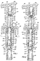
- Pump 110 comprises a hollow body 112 having an upper opening 114 in its upper end 116 and a lower opening 118 in its lower end 120.
- the body 112 is cylindrical and has a flange 122 extending radially outwardly from its upper end 116.
- vent 117 is provided in the upper end 116 of the body 112.
- the lower end 120 of the body 112 is tapered in the vicinity of the lower opening 118.
- a hollow tube 124 extends from the lower end of the body 112, and a diptube 126 which extends down into the container 128 bay be fitted onto tube 124. During operation of the pump 110, liquid is drawn up from container 128 through the diptube 126 into tube 124 and thence into pump 110.
- a hollow piston 130 which is slidable reciprocally with sealing fit in body 112 is fitted into the upper end 116 of body 112.
- Piston 130 has an upper end 132 with an opening 134 therein, and a lower end 136 with an opening 138 therein.
- piston 130 is cylindrical.
- the lower end 136 has a larger diameter than the upper end 132.
- An annular chamber 140 may be provided in the lower end 136 of the piston 130.
- piston seat 142 sized to be received inside piston 130 is fitted inside the piston 130 and the body 112. Piston seat 142 is slidable reciprocally inside piston 130. As shown in FIG. 3 , piston seat 142 has a larger diameter segment 144 at its lower end sized for sealing fit inside piston 130 when piston 130 is at the end of a downward stroke. A lower valve member 168 is located at the bottom of the smaller diameter segment 144. Preferably, the larger diameter segment has a flange 143 located between the lower valve member 168 and the segment 144. Flow passages 146 are provided in the larger diameter segment 144 so that liquid flowing up from the container 128 can enter the body 12.
- Piston seat 142 has a smaller diameter segment 148 at its upper end sized to provide a space between the exterior of the smaller diameter segment 148 and the inner walls 152 of the piston 130.
- the smaller diameter segment 148 is a sleeve, i.e. it has a central bore 149 extending downwardly from its upper end to about the larger diameter segment 144.
- the sleeve is a split sleeve, as shown in FIG. 6 , i.e., the bore 149 has channels 151 communicating with a chamber 150.
- Ribs 147 are provided on the outer walls of piston seat 142 to extend to about the inner diameter of the piston 130.
- Chamber 150 is defined by the inner walls of the piston 130, the inner walls of the body 112 and the outer walls of the piston seat 142.
- Means for biasing piston 130 against a downward stroke and for biasing it with an upward stroke is provided, and preferably comprises a coil spring 154.
- the upper end 156 of the coil spring 154 fits into annular chamber 140 in the lower end of piston 130.
- the lower end 158 of coil spring 154 may be located to act as a stop for the piston seat 142 by acting on the flange 143.
- An upper valve 160 is positioned in the upper end 132 of piston 130. Upper valve 160 is moveable to open the opening 134 in the upper end 132 of piston 130 during a downward stroke of piston 130 to dispense liquids from the chamber 150. Upper valve 160 is biased to be closed by the action of the biasing means. Upper valve 160 comprises an upper valve seat 164 formed in the upper end 132 of piston 130 and a valve member 162 having a stem 163 extending downwardly through the valve seat 164. Stem 163 is sized and adapted to be slidably fitted inside bore 149 of the smaller diameter segment 148 of piston seat 142. Stem 163 is sized to frictionally engage bore 149. Upper valve 160 is openable to dispense liquid from body 12 and piston 30 by a downward stroke of piston 30 because the upper valve seat 164 moves downwardly while the upper valve member 162 remains held stationary by the frictional engagement of stem 163 in bore 149.
- a lower valve 166 is positioned in the lower end of body 112.
- Lower valve 166 is moveable to open the opening 118 in lower end 120 of body 112 during an upward stroke of piston 130, to permit liquid to enter chamber 150.
- Lower valve 166 is biased to open the opening 118 in the lower end 120 of body 112.
- Lower valve 166 comprises a lower valve seat 170 formed in the lower end 120 of body 112 and the lower valve member 168 formed on the bottom of piston seat 142.
- Lower valve 166 is closeable by a downward stroke of piston 130 because of the force applied to the upper valve member 162 by the lower end of an actuator 180 causes the piston seat 142 to move downwardly, thereby seating the lower valve member 168 in the lower valve seat 170.
- Frictional engagement of the inner walls of the piston 130 with the ribs 147 on the piston seat 142 will similarly operate to close the lower valve 166.
- the frictional engagement of the inner walls of the piston 130 with the outer walls of the larger diameter segment 144 of the piston seat 142 will cause the lower valve member 166 to close.
- the actuator 180 may be seated on the upper end of piston 130.
- Actuator 180 has a nozzle 182 for dispensing liquid, and an upper surface 184 for finger actuation of the pump 110.
- Actuator 180 is adapted to press on the upper end of the upper valve member 162 after the upper valve 160 opens, and causes stem 163 to telescope inside bore 149 during the terminal portion of a downward stroke of the piston 130.
- Container closure 186 has a central aperture 188 through which extends the upper end 132 of piston 130. Piston 130 is retained in the body 112 by providing its lower end 136 with a larger diameter than its upper end 132 so that the lower end 136 cannot pass through the aperture 188 of the closure 186.
- Container closure 186 fits over the neck of the container 128, and may be held in place by screw threads formed on both, or by a snap fit combination.
- the container closure 186 further comprises a collar 190 extending upwardly from closure 186, and the holding means comprises mating threads 192 and 194 formed on the outer surface of actuator 180 and on the inner surface of collar 190.
- the various components of the pump 110 are formed of polymeric materials, preferably polypropylene or polyethylene.
- the coil spring is preferably formed of stainless steel.
- FIGS. 1-5 The operation of the pump 110 is shown in FIGS. 1-5. Beginning from the biased rest position shown in FIG. 1 with the piston 130 in the up position, the upper valve 166 is held closed by the frictional engagement of the stem 163 inside the bore 149 of the piston seat 142. Force applied to the actuator 180 causes the piston 130 to move downwardly, as shown in FIG. 2. During the downward stroke, the upper valve member member 162 remains stationary due to the frictional engagement of the stem 163 in the bore 149, while the valve seat 164 moves downwardly with the piston 130, so that the upper valve 160 is opened. As the actuator 180 and piston 130 continue through their downward stroke, as shown in FIGS. 2 and 3, the lower end of the actuator 180 contacts the upper end of upper valve member 162 and pushes on it.
- piston seat 142 moves downwardly until the lower valve member 168 seats in lower valve seat 170, closing lower valve 166.
- a lip or other protrusion may be provided on the inner walls of piston 130 at its upper end 32 to contact and press on the upper valve member 162 to push it downwardly.
- the piston seat 142 may also be moved downwardly by the frictional engagement of the ribs 147 with the downwardly moving piston 130.
- the upper valve 160 is opened and the lower valve 166 is closed, allowing the pressure in chamber 150 to increase so that the contents of the chamber 150 travel through the opening 134 and into the actuator 180 and are dispensed through actuator nozzle 182 during the remainder of the downward stroke.
- the inner walls of the lower end 136 of the piston 130 are sealingly fitted around the outer walls of the larger diameter segment 144 of the piston seat 142. If the pump is provided with holding means, the piston may be held at the end of the downward stroke, as shown in FIG. 4, to prevent leakage of the contents of the container.
- the piston 130 which is in frictional engagement with the larger diameter segment 144 of the piston seat 142 or the ribs 147 of the piston seat 142, carries the piston seat 142 upwardly and thereby opens the lower valve 166 by lifting the lower valve member 168 up off of the lower valve seat 170.
- the upper valve 160 remains open, since upper valve member 162 moves upwardly with the piston seat 142, and thus the valve seat 164, which is moving upwardly with the piston 130, does not contact the upper valve member 162.
- the upper valve 160 will close when the upper valve seat 164 contacts the upper valve member 162, and liquid will be drawn into the chamber 150 as previously described.
- vent 117 vents the container 128 to the compartment 196 defined by the closure 186, the body 112, and the piston 130, which compartment 196 is in turn vented to the atmosphere through the aperture 188 around the piston 130.
- the vent 117 allows the pressure in the container 128 to equilibrate with atmospheric pressure so that there is no build up of vacuum in the container 128 which would cause it to collapse and which would impede operation of the pump 110.
- the pump 110 provides a sealing closure of the container 128 when the piston 130 is sufficiently depressed so that the inner walls of the piston 130 slide onto the larger diameter segment 144 of the piston seat 142.
- This sealing closure can be maintained by the holding means described above to provide a sealed pump and container during transport of the container 128 and pump 110.
- the telescoping interaction between the upper and lower valve members holds the upper valve open during the initial portion of an upward stroke, so that the pump 110 can draw liquid at the nozzle 182 back into itself.
- the volume of the pump 110 which must be filled by each pump stroke is reduced, and also allows the creation of higher pressure differentials between the chamber 150 and the container 128 during each pump cycle, so that less liquid is required to prime the pump, and making it easier for the pump 110 to cause viscous liquids to be drawn into the chamber 150 when the pump 10 is being primed. Further, the action of the mechanically coupled valves is not impeded by viscous fluids.
- the described embodiment of the invention also provides a pump mechanism which is useable in any position. Since the operation of the pump is based on mechanically activated valves, the pump is unaffected by gravity, and it will provide effective pumping in any position.
Claims (4)
- Pumpe zum Abpumpen von Flüssigkeiten aus einem Behälter bestehend aus: einem an seinem oberen und unteren Ende mit Öffnungen versehenen hohlen Körper (112); einem hohlen Kolben (130) abdichtend und hin- und her verschiebbar in dem Körper, wobei der Kolben am oberen und unteren Ende mit Öffnungen versehen ist; einem Mittel (154), um den Kolben entgegen dem Abwärtshub vorzuspannen und den Kolben einer der oberen Lage zu halten; einer Kammer (148), welche durch den Kolben und das Gehäuse gebildet wird; einem Betätigungshebel (180), welcher am oberen Ende des Kolbens angreift;
wobei die Pumpe weiterhin besteht aus:
einem Kolbensitz (142) hin- und her verschiebbar innerhalb des Kolbens, wobei der Kolbensitz an seinem unteren Ende ein Segment (144) größeren Durchmessers aufweist, welches so dimensioniert ist, daß es am Ende des Abwärts-Kolbenhubs und am Anfang des Aufwärts-Kolbenhubs dichtend innerhalb des unteren Endes des Kolbens sitzt, wobei dieses Segment größeren Durchmessers am Boden ein unteres Ventilteil auf weist, und ein Segment (148) kleineren Durchmessers vorhanden ist, welches an seinem oberen Ende so dimensioniert ist, daß ein Hohlraum gebildet wird zwischen dem Segment kleineren Durchmessers und den Innenwänden des Kolbens, und welches eine Bohrung (149) aufweist;
einem oberen Ventil (160), welches sich am oberen Ende des kolbens (130) befindet, wobei das obere Ventil besteht aus einem oberen Ventilsitz (164) angeformt am oberen Ende des Kolbens (130) und einem oberen Ventilteil (162) mit einem sich nach unten erstreckenden Schaft (163), welcher verschiebbar innerhalb der Bohrung des Segmentes (148) kleineren Durchmessers des Kolbensitzes (142) gehalten wird, und der Schaft (163) reibungsschlüssig in die Bohrung (149) eingepasst ist, wobei das obere Ventil (160) sich öffnet, um Flüssigkeit während des Abwärtshubs des Kolbens (130) aus der Kammer hinauszubefördern, wobei der obere Ventilsitz (164) sich nach unten bewegt, während das obere ventilteil (162) an seiner Position verbleibt, gehalten vom Reibungseingriff des Schaftes in der Bohrung (149); und
einem unteren Ventil (166) am unteren Ende des Körpers (112), wobei das untere Ventil einen unteren Ventilsitz (170), angeformt am unteren Ende des Körpers (112) beinhaltet, und ein unteres Ventilteil (168) am unteren Ende des Kolbensitzes (142) angeformt ist, wobei das untere Ventil (166) durch den Abwärtshub des Kolbens (130) geschlossen wird und der Betätigungshebel (180) auf das obere Ventilteil (162) drückt, so daß der Kolbensitz (142) sich nach unten bewegt und das untere Ventilteil (168) auf den unteren Ventilsitz (170) drückt;
wobei die Pumpe gekennzeichnet ist durch Rippen (147), angeformt am Segment (148) kleineren Durchmessers am Kolbensitz (142), welche sich nach außen erstrecken und derart dimensioniert sind, daß sie reibungsschlüssig an der Innenwand des Kolbens (130) anliegen, wobei der Kolbensitz (142) während des Abwärtshubes des Kolbens (130) sich zusammen mit dem Kolben (130) nach unten bewegt und ein gleichzeitiges Schließen des unteren Ventils (166) bewirkt wird. - Eine Pumpe zum Abpumpen von Flüssigkeiten aus einem Behälter nach Anspruch 1, wobei der Betätigungshebel (180) vorgesehen ist, um auf das obere Ende des Ventilteils (162) zu drücken nachdem das obere Ventil (160) während eine Abwärtshubes geöffnet hat, wobei der Schaft (163) sich während des Abwärtshubes teleskopartig in die Bohrung des Kolbensitzes (142) hinein bewegt.
- Eine Pumpe zum Abpumpen von Flüssigkeiten aus einem Behälter nach einem der Ansprüche 1 oder 2, bestehend aus einer Behälterabdeckung (186) angebracht am oberen Ende des Körpers (112), welcher eine zentrale Öffnung (188) aufweist, durch welche sich das Segment kleineren Durchmessers des Kolbens (130) abdichtend verschiebbar erstreckt.
- Eine Pumpe zum Abpumpen von Flüssigkeiten aus einem Behälter nach einem der voranstehenden Ansprüche, bestehend aus Mitteln (192,194), um am Ende des Abwärtshubes den Kolben in seiner Position zu halten.
Applications Claiming Priority (3)
| Application Number | Priority Date | Filing Date | Title |
|---|---|---|---|
| US256327 | 1988-10-11 | ||
| US07/256,327 US4991747A (en) | 1988-10-11 | 1988-10-11 | Sealing pump |
| PCT/US1989/004495 WO1990003929A1 (en) | 1988-10-11 | 1989-10-05 | Sealing pump |
Publications (3)
| Publication Number | Publication Date |
|---|---|
| EP0407494A1 EP0407494A1 (de) | 1991-01-16 |
| EP0407494A4 EP0407494A4 (en) | 1992-01-22 |
| EP0407494B1 true EP0407494B1 (de) | 1994-09-21 |
Family
ID=22971831
Family Applications (1)
| Application Number | Title | Priority Date | Filing Date |
|---|---|---|---|
| EP89911677A Expired - Lifetime EP0407494B1 (de) | 1988-10-11 | 1989-10-05 | Auslasspumpe |
Country Status (4)
| Country | Link |
|---|---|
| US (1) | US4991747A (de) |
| EP (1) | EP0407494B1 (de) |
| DE (1) | DE68918441D1 (de) |
| WO (1) | WO1990003929A1 (de) |
Families Citing this family (35)
| Publication number | Priority date | Publication date | Assignee | Title |
|---|---|---|---|---|
| US5199167A (en) * | 1989-07-04 | 1993-04-06 | Societe Francaise D/Aerosols Et De Bouchage | Method of manufacture of miniature dispenser |
| FR2649382B1 (fr) * | 1989-07-04 | 1991-10-31 | Aerosols & Bouchage | Distributeurs miniatures |
| US5192006A (en) * | 1991-05-01 | 1993-03-09 | Risdon Corporation | Low profile pump |
| US5255823A (en) * | 1992-05-21 | 1993-10-26 | Risdon Corporation | Actuator and cap for a fluid dispenser |
| US5277340A (en) * | 1992-11-05 | 1994-01-11 | Risdon Corporation | Dispensing container |
| US5458289A (en) * | 1993-03-01 | 1995-10-17 | Bespak Plc | Liquid dispensing apparatus with reduced clogging |
| US5335858A (en) * | 1993-04-14 | 1994-08-09 | Dunning Walter B | Pump sprayer having leak preventing seals and closures |
| ATE189625T1 (de) * | 1993-06-23 | 2000-02-15 | American Cyanamid Co | Pistole zur abgabe von viskösen und halbviskösen produkten |
| US6000581A (en) * | 1993-06-23 | 1999-12-14 | American Cyanamid Company | Dispenser gun for viscous or semi-viscous products |
| US5816452A (en) * | 1993-06-23 | 1998-10-06 | American Cyanamid Company | Dispenser gun for viscous or semi-viscous products |
| DE9311935U1 (de) * | 1993-08-10 | 1993-10-21 | Baldwin Gegenheimer Gmbh | Flüssigkeits-Sprühvorrichtung für Druckmaschinen |
| GB9405891D0 (en) | 1994-03-24 | 1994-05-11 | English Glass Company The Limi | Dispenser pumps |
| US5425477A (en) * | 1994-06-29 | 1995-06-20 | Monturas, S.A. | Pump sprayer with stationary discharge |
| FR2723618B1 (fr) * | 1994-08-11 | 1996-10-31 | Sofab | Pompe a membrane |
| US5664706A (en) * | 1994-10-13 | 1997-09-09 | Bespak Plc | Apparatus for dispensing liquid in aerosol spray form |
| DE69638012D1 (de) * | 1995-01-27 | 2009-10-08 | Yoshino Kogyosho Co Ltd | Zerstäuberpumpe für Flüssigkeiten mit einem Öffnungsstempel für das Auslassventil |
| AU738185B2 (en) * | 1995-01-27 | 2001-09-13 | Yoshino Kogyosho Co., Ltd. | Liquid jet pump |
| US5806721A (en) * | 1995-12-15 | 1998-09-15 | Canyon Corporation | Container mounted pump dispenser with back suction |
| DE19606701A1 (de) * | 1996-02-22 | 1997-08-28 | Caideil M P Teoranta Tourmakea | Austragvorrichtung für Medien |
| CN2314128Y (zh) * | 1997-12-25 | 1999-04-14 | 丁要武 | 乳液泵防进水机构 |
| FR2784717B1 (fr) * | 1998-10-16 | 2001-12-07 | Sofab | Pompe de faible capacite a compatibilite amelioree |
| US6305571B1 (en) * | 2000-06-07 | 2001-10-23 | Donny Chu | Lid device with splashless baffle |
| FR2816375B1 (fr) * | 2000-11-07 | 2003-04-11 | Oreal | Pompe pour la distribution d'un produit, notamment un produit cosmetique ou de soin |
| US6516976B2 (en) * | 2000-12-19 | 2003-02-11 | Kimberly-Clark Worldwide, Inc. | Dosing pump for liquid dispensers |
| US6543651B2 (en) | 2000-12-19 | 2003-04-08 | Kimberly-Clark Worldwide, Inc. | Self-contained viscous liquid dispenser |
| FR2823184B1 (fr) * | 2001-04-04 | 2003-08-15 | Valois Sa | Pompe de distribution de produit fluide |
| US6695176B1 (en) * | 2002-08-08 | 2004-02-24 | Saint-Gobain Calmar Inc. | Pump dispenser having an improved discharge valve |
| DE10334032B4 (de) * | 2003-07-18 | 2005-06-23 | Ing. Erich Pfeiffer Gmbh | Ventileinrichtung |
| CA2470532C (en) * | 2004-06-09 | 2008-11-18 | Hygiene-Technik Inc. | Draw back pump |
| US20070080173A1 (en) * | 2005-10-06 | 2007-04-12 | Coe Matthew T | Fluid dispenser with a safety dispensing actuator |
| CN101945604B (zh) * | 2008-02-18 | 2013-08-14 | Sca卫生用品公司 | 具有回吸机构的一次性泵 |
| DE102008027599A1 (de) * | 2008-06-10 | 2009-12-31 | Meadwestvaco Calmar Gmbh | Fluidaustragkopf |
| GB0912065D0 (en) * | 2009-07-10 | 2009-08-19 | Reckitt & Colman Overseas | A fluid delivery system |
| ITMI20131251A1 (it) * | 2013-07-25 | 2015-01-26 | Meadwestvaco Calmar S R L | Pompa ad azionamento manuale per l'erogazione di sostanze fluide, ad azionamento facilitato |
| IT202000023515A1 (it) * | 2020-10-06 | 2022-04-06 | Coster Tecnologie Speciali Spa | Dispositivo di erogazione di una sostanza fluida |
Family Cites Families (15)
| Publication number | Priority date | Publication date | Assignee | Title |
|---|---|---|---|---|
| US1196584A (en) * | 1915-10-16 | 1916-08-29 | George T Randolph | Pump-piston. |
| US3128018A (en) * | 1961-07-07 | 1964-04-07 | Drackett Co | Fluid dispensing pump with sealing means |
| US3185354A (en) * | 1963-06-04 | 1965-05-25 | Valve Corp Of America | Pump dispensing device for liquid containers |
| FR1399208A (fr) * | 1963-06-21 | 1965-05-14 | Lanvin Parfums | Pulvérisateur |
| US3187960A (en) * | 1964-05-08 | 1965-06-08 | Sterling Drug Inc | Non-metallic pump dispenser |
| US3362344A (en) * | 1966-03-01 | 1968-01-09 | Calmar Inc | Liquid dispenser |
| US3362343A (en) * | 1966-03-01 | 1968-01-09 | Clamar Inc | Liquid dispenser |
| US3391647A (en) * | 1967-01-30 | 1968-07-09 | Calmar Inc | Liquid dispensing pump |
| FR1509866A (fr) * | 1967-02-02 | 1968-01-12 | Calmar | Distributeur de liquide |
| CA1008825A (en) * | 1974-03-28 | 1977-04-19 | William E. Warren | Pump assembly for an atomizing piston pump |
| GB1470597A (en) * | 1974-08-21 | 1977-04-14 | Sterling Winthrop Group Ltd | Reciprocating pumps for dispensing pastes liquids and other substances |
| DE2902624C2 (de) * | 1979-01-24 | 1985-10-10 | Pfeiffer Zerstäuber Vertriebsgesellschaft mbH & Co KG, 7760 Radolfzell | Ausgabepumpe |
| US4286736A (en) * | 1980-02-20 | 1981-09-01 | Diamond International Corporation | Liquid Dispenser |
| US4340158A (en) * | 1980-06-13 | 1982-07-20 | Realex Corporation | Vent-sealing, down-locked pump dispenser |
| US4524888A (en) * | 1981-07-30 | 1985-06-25 | Canyon Corporation | Dispenser |
-
1988
- 1988-10-11 US US07/256,327 patent/US4991747A/en not_active Expired - Lifetime
-
1989
- 1989-10-05 DE DE68918441T patent/DE68918441D1/de not_active Expired - Lifetime
- 1989-10-05 EP EP89911677A patent/EP0407494B1/de not_active Expired - Lifetime
- 1989-10-05 WO PCT/US1989/004495 patent/WO1990003929A1/en active IP Right Grant
Also Published As
| Publication number | Publication date |
|---|---|
| EP0407494A4 (en) | 1992-01-22 |
| US4991747A (en) | 1991-02-12 |
| WO1990003929A1 (en) | 1990-04-19 |
| EP0407494A1 (de) | 1991-01-16 |
| DE68918441D1 (de) | 1994-10-27 |
Similar Documents
| Publication | Publication Date | Title |
|---|---|---|
| EP0407494B1 (de) | Auslasspumpe | |
| EP0179853B1 (de) | Pumpe zur verteilung einer flüssigkeit aus einem behälter | |
| US4986453A (en) | Atomizing pump | |
| US10335816B1 (en) | All plastic water resistant pump | |
| US5192006A (en) | Low profile pump | |
| US4735347A (en) | Single puff atomizing pump dispenser | |
| EP0755305B1 (de) | Handbetätigte flüssigkeitshubkolbenpumpe | |
| US4434916A (en) | Manually operated liquid dispensing pump | |
| EP2892656B1 (de) | Schaumspender | |
| US6021924A (en) | Manually controlled metering pump for bottles with deformable sheaths | |
| US2884164A (en) | Fluid dispenser | |
| CA2617202C (en) | Vacuum release mechanism | |
| US4056216A (en) | Liquid dispensing pump automatically sealable against leakage | |
| US5301852A (en) | Manually operated pump for dispensing liquid or creamy substances at a predetermined constant pressure | |
| US4503997A (en) | Dispensing pump adapted for pressure filling | |
| US5108013A (en) | Pump for dispensing liquid from a container | |
| US7988021B2 (en) | Sliding-jacket pump | |
| US4953758A (en) | Valve construction | |
| CA3064689C (en) | All plastic water resistant pump | |
| GB2212477A (en) | Metering dispenser for inverted bottle | |
| JPH0518665U (ja) | デイスペンサー |
Legal Events
| Date | Code | Title | Description |
|---|---|---|---|
| PUAI | Public reference made under article 153(3) epc to a published international application that has entered the european phase |
Free format text: ORIGINAL CODE: 0009012 |
|
| 17P | Request for examination filed |
Effective date: 19901002 |
|
| AK | Designated contracting states |
Kind code of ref document: A1 Designated state(s): DE FR GB IT |
|
| A4 | Supplementary search report drawn up and despatched |
Effective date: 19911202 |
|
| AK | Designated contracting states |
Kind code of ref document: A4 Designated state(s): DE FR GB IT |
|
| 17Q | First examination report despatched |
Effective date: 19921009 |
|
| GRAA | (expected) grant |
Free format text: ORIGINAL CODE: 0009210 |
|
| AK | Designated contracting states |
Kind code of ref document: B1 Designated state(s): DE FR GB IT |
|
| PG25 | Lapsed in a contracting state [announced via postgrant information from national office to epo] |
Ref country code: IT Free format text: LAPSE BECAUSE OF FAILURE TO SUBMIT A TRANSLATION OF THE DESCRIPTION OR TO PAY THE FEE WITHIN THE PRE;WARNING: LAPSES OF ITALIAN PATENTS WITH EFFECTIVE DATE BEFORE 2007 MAY HAVE OCCURRED AT ANY TIME BEFORE 2007. THE CORRECT EFFECTIVE DATE MAY BE DIFFERENT FROM THE ONE RECORDED.SCRIBED TIME-LIMIT Effective date: 19940921 |
|
| REF | Corresponds to: |
Ref document number: 68918441 Country of ref document: DE Date of ref document: 19941027 |
|
| ET | Fr: translation filed | ||
| PG25 | Lapsed in a contracting state [announced via postgrant information from national office to epo] |
Ref country code: DE Effective date: 19941222 |
|
| PLBE | No opposition filed within time limit |
Free format text: ORIGINAL CODE: 0009261 |
|
| STAA | Information on the status of an ep patent application or granted ep patent |
Free format text: STATUS: NO OPPOSITION FILED WITHIN TIME LIMIT |
|
| 26N | No opposition filed | ||
| REG | Reference to a national code |
Ref country code: FR Ref legal event code: CD |
|
| REG | Reference to a national code |
Ref country code: GB Ref legal event code: IF02 |
|
| REG | Reference to a national code |
Ref country code: GB Ref legal event code: 732E |
|
| REG | Reference to a national code |
Ref country code: GB Ref legal event code: 732E |
|
| REG | Reference to a national code |
Ref country code: FR Ref legal event code: TP |
|
| PGFP | Annual fee paid to national office [announced via postgrant information from national office to epo] |
Ref country code: GB Payment date: 20030922 Year of fee payment: 15 |
|
| PGFP | Annual fee paid to national office [announced via postgrant information from national office to epo] |
Ref country code: FR Payment date: 20030923 Year of fee payment: 15 |
|
| PG25 | Lapsed in a contracting state [announced via postgrant information from national office to epo] |
Ref country code: GB Free format text: LAPSE BECAUSE OF NON-PAYMENT OF DUE FEES Effective date: 20041005 |
|
| GBPC | Gb: european patent ceased through non-payment of renewal fee |
Effective date: 20041005 |
|
| PG25 | Lapsed in a contracting state [announced via postgrant information from national office to epo] |
Ref country code: FR Free format text: LAPSE BECAUSE OF NON-PAYMENT OF DUE FEES Effective date: 20050630 |
|
| REG | Reference to a national code |
Ref country code: FR Ref legal event code: ST |