EP0407076B1 - Faseroptisches Kabel - Google Patents
Faseroptisches Kabel Download PDFInfo
- Publication number
- EP0407076B1 EP0407076B1 EP90306924A EP90306924A EP0407076B1 EP 0407076 B1 EP0407076 B1 EP 0407076B1 EP 90306924 A EP90306924 A EP 90306924A EP 90306924 A EP90306924 A EP 90306924A EP 0407076 B1 EP0407076 B1 EP 0407076B1
- Authority
- EP
- European Patent Office
- Prior art keywords
- cable
- optical
- channel
- ribbon
- slot
- Prior art date
- Legal status (The legal status is an assumption and is not a legal conclusion. Google has not performed a legal analysis and makes no representation as to the accuracy of the status listed.)
- Expired - Lifetime
Links
- 239000013307 optical fiber Substances 0.000 title claims abstract description 20
- 230000003287 optical effect Effects 0.000 claims abstract description 51
- 230000000903 blocking effect Effects 0.000 claims abstract description 7
- 230000009974 thixotropic effect Effects 0.000 claims abstract description 7
- XLYOFNOQVPJJNP-UHFFFAOYSA-N water Substances O XLYOFNOQVPJJNP-UHFFFAOYSA-N 0.000 claims abstract description 7
- 238000004519 manufacturing process Methods 0.000 claims description 6
- 239000004519 grease Substances 0.000 claims description 5
- 238000000034 method Methods 0.000 claims description 3
- 238000005452 bending Methods 0.000 claims 1
- 239000003989 dielectric material Substances 0.000 claims 1
- 239000000499 gel Substances 0.000 claims 1
- 235000015110 jellies Nutrition 0.000 claims 1
- 239000008274 jelly Substances 0.000 claims 1
- 239000007788 liquid Substances 0.000 claims 1
- 239000000463 material Substances 0.000 description 8
- 239000000835 fiber Substances 0.000 description 6
- 238000001125 extrusion Methods 0.000 description 4
- 239000011230 binding agent Substances 0.000 description 3
- 239000004033 plastic Substances 0.000 description 3
- 229920003023 plastic Polymers 0.000 description 3
- 238000010276 construction Methods 0.000 description 2
- 238000003780 insertion Methods 0.000 description 2
- 230000037431 insertion Effects 0.000 description 2
- 230000007935 neutral effect Effects 0.000 description 2
- 229920002430 Fibre-reinforced plastic Polymers 0.000 description 1
- 239000000853 adhesive Substances 0.000 description 1
- 230000001070 adhesive effect Effects 0.000 description 1
- 230000005540 biological transmission Effects 0.000 description 1
- 239000011248 coating agent Substances 0.000 description 1
- 238000000576 coating method Methods 0.000 description 1
- 239000003000 extruded plastic Substances 0.000 description 1
- 239000011151 fibre-reinforced plastic Substances 0.000 description 1
- 230000006698 induction Effects 0.000 description 1
- 238000002347 injection Methods 0.000 description 1
- 239000007924 injection Substances 0.000 description 1
- 238000009434 installation Methods 0.000 description 1
- 229920001684 low density polyethylene Polymers 0.000 description 1
- 239000004702 low-density polyethylene Substances 0.000 description 1
- 230000013011 mating Effects 0.000 description 1
Images
Classifications
-
- G—PHYSICS
- G02—OPTICS
- G02B—OPTICAL ELEMENTS, SYSTEMS OR APPARATUS
- G02B6/00—Light guides; Structural details of arrangements comprising light guides and other optical elements, e.g. couplings
- G02B6/44—Mechanical structures for providing tensile strength and external protection for fibres, e.g. optical transmission cables
- G02B6/4401—Optical cables
- G02B6/4403—Optical cables with ribbon structure
-
- G—PHYSICS
- G02—OPTICS
- G02B—OPTICAL ELEMENTS, SYSTEMS OR APPARATUS
- G02B6/00—Light guides; Structural details of arrangements comprising light guides and other optical elements, e.g. couplings
- G02B6/44—Mechanical structures for providing tensile strength and external protection for fibres, e.g. optical transmission cables
- G02B6/4401—Optical cables
- G02B6/4407—Optical cables with internal fluted support member
- G02B6/4408—Groove structures in support members to decrease or harmonise transmission losses in ribbon cables
-
- G—PHYSICS
- G02—OPTICS
- G02B—OPTICAL ELEMENTS, SYSTEMS OR APPARATUS
- G02B6/00—Light guides; Structural details of arrangements comprising light guides and other optical elements, e.g. couplings
- G02B6/44—Mechanical structures for providing tensile strength and external protection for fibres, e.g. optical transmission cables
- G02B6/4401—Optical cables
- G02B6/4415—Cables for special applications
- G02B6/4416—Heterogeneous cables
- G02B6/4422—Heterogeneous cables of the overhead type
Definitions
- This invention relates to an optical fibre cable comprising an optical fibre ribbon element housed in a longitudinal channel of the cable, and relates particularly but not exclusively to an aerial optical fibre cable which has an all-dielectric or substantially all-dielectric construction, and suitable for installation alongside high voltage power transmission lines.
- This cable construction provides strain relief for the ribbon optical fibre element by ensuring that the element inside the core is longer than the cable so that when the cable is put under tension and the core stretches, the element is not put under tension.
- an optical fibre cable consisting of an electrically non-conductive core (1) having a longitudinal channel or slot (2) within which a self-supporting optical fibre ribbon element (3) is disposed, there being an excess length of ribbon element relative to the length of the core, characterised in that a non-optical ribbon or strip element (3A) of similar tensile modulus to that of the optical ribbon is disposed in the channel extending alongside and in abutment with the optical ribbon element, and that both elements adopt together an undulating configuration within the channel whereby to distribute evenly the excess optical ribbon element along the cable.
- a non-optical ribbon or strip element (3A) of similar tensile modulus to that of the optical ribbon is disposed in the channel extending alongside and in abutment with the optical ribbon element, and that both elements adopt together an undulating configuration within the channel whereby to distribute evenly the excess optical ribbon element along the cable.
- a method of making an optical fibre cable comprising providing an electrically non-conductive core member (1) having a longitudinal channel or slot (2), and introducing into said slot an excess length of a self-supporting optical fibre ribbon element (3), characterised in that a further, non-optical ribbon element (3A) having a tensile modulus similar to that of the optical element is introduced into the channel together with and in abutment with the optical element whereby both elements adopt together an undulating configuration within the channel so as to distribute evenly the excess optical ribbon element length along the cable.
- a further, non-optical ribbon element (3A) having a tensile modulus similar to that of the optical element is introduced into the channel together with and in abutment with the optical element whereby both elements adopt together an undulating configuration within the channel so as to distribute evenly the excess optical ribbon element length along the cable.
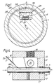
- a non-electrically conductive slotted core 1 of homogenous material is made from glass-fibre-reinforced plastics by a "pultrusion" or similar process, and has a rectangular slot 2 with convexly-radiused edges 2B and containing an optical fibre ribbon element 3 lying in the slot 2.
- the core 1 act as the cable tensile strength member and armouring (being highly crush-resistant) and is resilient with a modulus of at least 40,000N/mm2.
- the slot 2 runs straight along the profile (core) 1 parallel to the central longitudinal axis 1A and is referred to as a surfacial slot. It is always located to one side of the centre of the core, the centre being referenced 1A, and to one side also of the neutral axis 1B.
- a ribbon insert of a predetermined tensile modulus the same as or very similar to that of the optical element and which lies against the optical ribbon element.
- Both the optical and non-optical elements adopt the same undulating configuration as shown in Fig. 3 although they are separate elements.
- This undulation is in the form of a uniform waveform along the length of the cable. This undulation, when the cable is in service, i.e. suspended between pylons which may be up to 300m apart enables the fibres of the optical element to be isolated from any strain seen by the core.
- the insert non-optical ribbon is made from a cheap polymeric material which has been extruded.
- the width of the slot 2 is about 3mm and both ribbon elements are about 1.5 to 2mm wide.
- the optical ribbon comprises up to six optical fibres held side-by-side by a thin coating of air-dried adhesive such as disclosed in our published British Patent No. 2181271.
- the slot 2 is closed by a cap 5 made of extruded plastics material and having concavely radiussed edges 5B which exactly fit onto the edges 2B.
- the slot 2 is filled with a grease-like material 28, for example one sold under the brand name SYNTEC Type 270 and which is a soft thixotropic water blocking material.
- a binder 6 which is helically wound around and serves to locate the cap 5 in place on top of the slot 2 prior to extrusion of the outer sheath 7 and during the induction of an excess length of the elements 3 and 3A around the large capstan, to be described later.
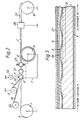
- the profile 1 is run from a storage reel 7 having a brake 8 which can be applied to brake rotation of the reel 7.
- the core 1 passes from the reel 7 through various stages over a capstan 9 and onto a storage drum 10.
- Ribbon fibre element 3 is drawn from reel 3 and enters the slot 2 of the profile.
- the insert ribbon 3A is drawn from reel 3'A.
- the ribbon insertion station 11 comprises a casing 12 having a hollow interior 13 through which the profile 1 passes via an entrance port 14 and an exit port 15.
- an orientation plate 16 in the form of a guide shoe having a gently-curved surface 16A around which the optical fibre ribbon and non-optical ribbon elements 3 and 3A are guided into the bottom of the slot 2 as the core 1 is drawn through the casing 12.
- an injection port 19 Through which a water blocking gel 28 such as "Syntec" is injected into the casing and is applied to the slot 2. Also in the casing is a pressure sensor 20 for sensing the pressure filling grease or gel in the casing and controlling the rate of application of the grease or gel accordingly.
- a water blocking gel 28 such as "Syntec”
- a pressure sensor 20 for sensing the pressure filling grease or gel in the casing and controlling the rate of application of the grease or gel accordingly.
- the cap 5 is fed from a reel 5A and bent over a guide arrangement so that the mating radiussed surfaces 5B and 2B mate and fit together.
- the fit is a friction fit but enables the cap to nevertheless be easily removed for access to the fibres for e.g. jointing.
- the core 1 then enters a binding station 25 which helically applies the binder 6 to hold the cap firmly in place.
- the core is then applied to the large capstan 9 which is about 1m in diameter and because the slot containing the optical and non-optical ribbon elements is on the outside as it passes around the capstan so the length of the slot in the cable lying on the capstan is greater than the length of the core as measured at its neutral axis (very close to central axis 1A).
- the slot in the core when it leaves the capstan indicated in Fig. 2 by the reference numeral 1' has induced in it an excess length of the elements 3, 3A.
- the excess length is drawn from the supply reels 3' and 3'A and the thixotropic nature of the filling gel allows movement of the ribbon elements in order for the excess to be induced around the capstan but is sufficiently firm under conditions of no mechanical shear that it holds the ribbons in a wavy or undulating configuration along the slot when the core leaves the capstan 9.
- the core and binder is then sheathed (27) in a plastics extrusion head 26 using preferably low density polyethylene, although other plastics materials can be used according to requirements.
- the extrusion head is shown on line in Fig. 2 but it could be off line, that is to say a separate extrusion line can be provided.
- capstan is the main driving force for pulling the core through the apparatus.
- the addition of the non-optical ribbon helps ensure that the wavy or undulating configuration of the optical ribbon is regular and uniform.
- a suitable filling medium such as SYNTEC 270S
- the excess length of optical and non-optical ribbon can be easily and effectively induced using the capstan 9 with the filling medium already injected into the slot.
- the capstan is located relatively close to the fibre supply reel 3A. It is also important that the yield point of the thixotropic filling gel is low enough to enable the regular undulating configuration of the elements to be adopted within the gel 28 yet high enough to maintain the configuration in normal use of the cable.
- the filling medium 28 is forced into the slot 2 in head 11 at a pressure in the range 0.1 to 0.2 p.s.i. as measured in the head 11.
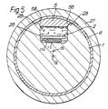
- Fig 5 shows an embodiment similar to Fig 1 and like reference numerals represent like parts.
- An optical element 53 and non-optical element 53A cover each other.
- Fig 5 differs from Fig 1 in that here the non-optical element 53A is located above the optical element 53, the elements are of different sizes, and the filling water-blocking gel 28 is of different manufacture and viscosity.
- Optical element 53 contains eight or less optical fibres and has a width significantly less than the width of the channel 2.
- Non-optical element 53A is wider than the optical element, equal in fact to the width of the channel 2 so that it is a loose fit widthwise in the channel, there being a gap on each side of between 1 and 5 thousandths of an inch (25 to 125 microns).
- the filling gel is made by Dow under the trade name Optigard, type reference Q23314. Over a shear rate range of 200/sec carried out over a time of 55 mins, the yield value varies from 220 pascals to 450 pascals, and the apparent viscosity at yield varies from 150 pascals secs to 750 pascal secs. The apparent viscosity at 200 pascal secs drop to 10 pascal secs and the stable operating temperature of the material is -55°C to +200°C.
- a full width optical ribbon i.e. one having the same width as the dummy ribbon would accommodate fourteen fibres in the size of cable and size of channel shown here. Two such elements would provide twenty eight fibres.
- the present invention enables an excess length of optical element to be uniformally distributed along the cable core during manufacture and maintained in use of the cable.
- Each optical element referred to herein, be it low or high fibre count is a self-supporting element.
- the non-optical element is separate from the optical element and merely assists in guiding the optical element into the desired waveform uniformally along the cable. It does not form a structural part of the optical element.
Landscapes
- Physics & Mathematics (AREA)
- General Physics & Mathematics (AREA)
- Optics & Photonics (AREA)
- Communication Cables (AREA)
- Light Guides In General And Applications Therefor (AREA)
- Optical Fibers, Optical Fiber Cores, And Optical Fiber Bundles (AREA)
- Optical Communication System (AREA)
- Mechanical Coupling Of Light Guides (AREA)
Claims (9)
- Faseroptisches Kabel mit einem elektrisch nichtleitenden Kern (1) mit einem längsverlaufenden Kanal oder Schlitz (2), in dem ein selbsttragendes bandförmiges faseroptisches Element (3) angeordnet ist, wobei sich eine überschüssige Länge des bandförmigen faseroptischen Elementes bezogen auf die Länge des Kerns ergibt,
dadurch gekennzeichnet, daß ein keine optischen Eigenschaften aufweisendes Band- oder Streifenelement (3A) mit einem ähnlichen Zugelastizitätsmodul wie der des faseroptischen Bandes in dem Kanal angeordnet ist und sich entlang und in Anlage an dem bandförmigen faseroptischen Element erstreckt, und daß beide Elemente zusammen eine wellenförmige Form in dem Kanal annehmen, um auf diese Weise gleichförmig die überschüssige Länge des bandförmigen faseroptischen Elementes entlang des Kabels zu verteilen. - Kabel nach Anspruch 1,
dadurch gekennzeichnet, daß der Kanal (2) mit einem Fett, einer Gallerte oder einer ähnlichen viskosen, wasserabsperrenden Flüssigkeit (28, 28A) gefüllt ist. - Kabel nach Anspruch 2,
gekennzeichnet durch einen Kern (1), der aus einem eine hohe Zugfestigkeit aufweisenden Isoliermaterial hergestellt ist und das Zugkräfte aufnehmende Bauteil des Kabels bildet. - Kabel nach einem der vorhergehenden Ansprüche,
dadurch gekennzeichnet, daß die überschüssige Länge des bandförmigen faseroptischen Elementes im Bereich von 0,5% bis 1% liegt, wenn das Kabel gestreckt liegt. - Kabel nach einem der vorhergehenden Ansprüche,
ddurch gekennzeichnet, daß das faseroptische Element (3, 53) schmaler als der Kanal ist. - Kabel nach einem der vorhergehenden Ansprüche,
dadurch gekennzeichnet, daß das keine optischen Eigenschaften aufweisende Element (53A) über dem faseroptischen Element (53) in dem Kanal liegt. - Verfahren zur Herstellung eines faseroptischen Kabels, bei dem ein elektrisch nicht leitendes Kernbauteil (1) mit einem längsverlaufenden Kanal oder Schlitz geschaffen und in den Schlitz eine überschüssige Länge eines selbsttragenden bandförmigen fasroptischen Elementes (3) eingeführt wird, dadurch gekennzeichnet, daß ein weiteres, keine optischen Eigenschaften aufweisendes bandförmiges Element (3A) mit einem Zugelastizitätsmodul ähnlich dem des faseroptischen Elementes in den Kanal zusammen mit und in Anlage an dem faseroptischen Element eingeführt wird, so daß beide Elemente zusammen eine Wellenfom in dem Kanal annehmen, um auf diese Weise die überschüssige Länge des faseroptischen bandförmigen Elementes entlang des Kabels zu verteilen.
- Verfahren nach Anspruch 7,
dadurch gekennzeichnet, daß der Kanal (2) mit einem wasserabsperrenden tixotropen Gel oder Fett (28) gefüllt wird, und daß die regelmäßige Wellenform hervorgerufen wird, nachdem der Kanal (2) gefüllt wurde. - Verfahen nach Anspruch 7 oder 8,
dadurch gekennzeichnet, daß die überschüssige Länge durch Biegen des Kabelteils (1) auf einer gekrümmten Bahn (9) derart erreicht wird, daß der Kanal (2) gedehnt wird, solange sich der Kabelteil (1) auf der gekrümmten Bahn (9) befindet.
Priority Applications (1)
| Application Number | Priority Date | Filing Date | Title |
|---|---|---|---|
| AT90306924T ATE91800T1 (de) | 1989-07-01 | 1990-06-25 | Faseroptisches kabel. |
Applications Claiming Priority (2)
| Application Number | Priority Date | Filing Date | Title |
|---|---|---|---|
| GB8915177 | 1989-07-01 | ||
| GB8915177A GB2233779B (en) | 1989-07-01 | 1989-07-01 | Optical fibre cable |
Publications (2)
| Publication Number | Publication Date |
|---|---|
| EP0407076A1 EP0407076A1 (de) | 1991-01-09 |
| EP0407076B1 true EP0407076B1 (de) | 1993-07-21 |
Family
ID=10659413
Family Applications (1)
| Application Number | Title | Priority Date | Filing Date |
|---|---|---|---|
| EP90306924A Expired - Lifetime EP0407076B1 (de) | 1989-07-01 | 1990-06-25 | Faseroptisches Kabel |
Country Status (12)
| Country | Link |
|---|---|
| US (1) | US5082380A (de) |
| EP (1) | EP0407076B1 (de) |
| JP (1) | JP2836928B2 (de) |
| AT (1) | ATE91800T1 (de) |
| AU (1) | AU623271B2 (de) |
| CA (1) | CA2019902C (de) |
| DE (1) | DE69002285T2 (de) |
| ES (1) | ES2044447T3 (de) |
| GB (1) | GB2233779B (de) |
| IN (1) | IN180638B (de) |
| NZ (1) | NZ234274A (de) |
| ZA (1) | ZA904988B (de) |
Families Citing this family (26)
| Publication number | Priority date | Publication date | Assignee | Title |
|---|---|---|---|---|
| US5179611A (en) * | 1990-07-17 | 1993-01-12 | Tokai Rubber Industries, Ltd. | Optical fiber cable having a water absorptive member |
| GB2255836B (en) * | 1991-05-11 | 1995-11-08 | Northern Telecom Ltd | Fibre optic cable |
| JP2680943B2 (ja) * | 1991-06-03 | 1997-11-19 | 住友電気工業株式会社 | 光ケーブル |
| US5348586A (en) * | 1993-10-29 | 1994-09-20 | Siecor Corporation | Ribbon prewet system |
| US5542020A (en) * | 1994-06-10 | 1996-07-30 | Commscope, Inc. | Fiber optic cable having extended contraction window and associated method and apparatus for fabricating the cable |
| CN1062663C (zh) * | 1994-07-06 | 2001-02-28 | 古河电气工业株式会社 | 光缆 |
| US5668912A (en) * | 1996-02-07 | 1997-09-16 | Alcatel Na Cable Systems, Inc. | Rectangular optical fiber cable |
| ES2114807B1 (es) * | 1996-02-13 | 1999-02-16 | Telefonica Nacional Espana Co | Tritubo estriado y lubricado para cables de fibra optica. |
| US6178278B1 (en) | 1997-11-13 | 2001-01-23 | Alcatel | Indoor/outdoor dry optical fiber cable |
| NL1010182C2 (nl) | 1997-11-27 | 2001-01-10 | Koninkl Kpn Nv | Kabel met optische vezel-ribbons. |
| US6085009A (en) * | 1998-05-12 | 2000-07-04 | Alcatel | Water blocking gels compatible with polyolefin optical fiber cable buffer tubes and cables made therewith |
| US6169834B1 (en) | 1998-05-13 | 2001-01-02 | Alcatel | Slotted composite cable having a cable housing with a tubular opening for copper pairs and a slot for an optical fiber |
| US6253012B1 (en) | 1998-11-12 | 2001-06-26 | Alcatel | Cycled fiber lock for cross-functional totally dry optical fiber loose tube cable |
| US20060140557A1 (en) * | 2001-03-30 | 2006-06-29 | Parris Donald R | Fiber optic cable with strength member formed from a sheet |
| US6748147B2 (en) | 2001-03-30 | 2004-06-08 | Corning Cable Systems Llc | High strength fiber optic cable |
| US6714708B2 (en) | 2001-03-30 | 2004-03-30 | Corning Cable Systems Llc | Fiber optic with high strength component |
| US6621964B2 (en) | 2001-05-21 | 2003-09-16 | Corning Cable Systems Llc | Non-stranded high strength fiber optic cable |
| US6618526B2 (en) | 2001-09-27 | 2003-09-09 | Corning Cable Systems Llc | Fiber optic cables |
| US7116865B2 (en) * | 2002-12-10 | 2006-10-03 | International Business Machines Corporation | Apparatus and methods for remakeable connections to optical waveguides |
| US7471862B2 (en) | 2002-12-19 | 2008-12-30 | Corning Cable Systems, Llc | Dry fiber optic cables and assemblies |
| US7415181B2 (en) * | 2005-07-29 | 2008-08-19 | Corning Cable Systems Llc | Fiber optic cables and assemblies for fiber to the subscriber applications |
| NL1033918C2 (nl) * | 2007-05-31 | 2008-12-02 | Draka Comteq Bv | Kabel, alsmede gebruik en werkwijze voor het aanleggen van een kabelnetwerk. |
| AU2010227148A1 (en) * | 2009-03-27 | 2011-09-29 | Nexans | An optical fibre conduit, an electrical power cable and a method of manufacturing same |
| US9063315B2 (en) * | 2013-09-24 | 2015-06-23 | Baker Hughes Incorporated | Optical cable, downhole system having optical cable, and method thereof |
| JP5954350B2 (ja) * | 2014-01-31 | 2016-07-20 | 住友金属鉱山株式会社 | スカンジウム回収方法 |
| US11668872B2 (en) * | 2019-08-21 | 2023-06-06 | Schlumberger Technology Corporation | Cladding for an electro-optical device |
Citations (1)
| Publication number | Priority date | Publication date | Assignee | Title |
|---|---|---|---|---|
| GB2156095A (en) * | 1984-03-14 | 1985-10-02 | Bicc Plc | An improved flexible elongate optical fibre cable |
Family Cites Families (5)
| Publication number | Priority date | Publication date | Assignee | Title |
|---|---|---|---|---|
| GB1598438A (en) * | 1977-05-13 | 1981-09-23 | Bicc Ltd | Overhead electric transmission systems |
| EP0216548B1 (de) * | 1985-09-14 | 1995-03-08 | Nortel Networks Corporation | Optisches Kabel |
| CA1299412C (en) * | 1986-09-19 | 1992-04-28 | Nobuhiro Akasaka | Optical fiber cable preventing water from spreading toward cable interior |
| GB2201008B (en) * | 1987-02-12 | 1991-10-23 | Stc Plc | Optical fibre cables |
| GB2237655B (en) * | 1989-10-12 | 1993-04-28 | Stc Plc | Aerial optical fibre cable |
-
1989
- 1989-07-01 GB GB8915177A patent/GB2233779B/en not_active Expired - Fee Related
-
1990
- 1990-06-25 AT AT90306924T patent/ATE91800T1/de not_active IP Right Cessation
- 1990-06-25 DE DE90306924T patent/DE69002285T2/de not_active Expired - Fee Related
- 1990-06-25 ES ES90306924T patent/ES2044447T3/es not_active Expired - Lifetime
- 1990-06-25 EP EP90306924A patent/EP0407076B1/de not_active Expired - Lifetime
- 1990-06-27 ZA ZA904988A patent/ZA904988B/xx unknown
- 1990-06-27 AU AU57930/90A patent/AU623271B2/en not_active Ceased
- 1990-06-27 NZ NZ234274A patent/NZ234274A/en unknown
- 1990-06-27 US US07/544,678 patent/US5082380A/en not_active Expired - Lifetime
- 1990-06-27 IN IN655DE1990 patent/IN180638B/en unknown
- 1990-06-27 CA CA002019902A patent/CA2019902C/en not_active Expired - Fee Related
- 1990-06-29 JP JP2174308A patent/JP2836928B2/ja not_active Expired - Lifetime
Patent Citations (1)
| Publication number | Priority date | Publication date | Assignee | Title |
|---|---|---|---|---|
| GB2156095A (en) * | 1984-03-14 | 1985-10-02 | Bicc Plc | An improved flexible elongate optical fibre cable |
Also Published As
| Publication number | Publication date |
|---|---|
| DE69002285T2 (de) | 1993-11-04 |
| EP0407076A1 (de) | 1991-01-09 |
| JP2836928B2 (ja) | 1998-12-14 |
| GB2233779B (en) | 1993-05-05 |
| AU623271B2 (en) | 1992-05-07 |
| DE69002285D1 (de) | 1993-08-26 |
| ZA904988B (en) | 1991-04-24 |
| ATE91800T1 (de) | 1993-08-15 |
| ES2044447T3 (es) | 1994-01-01 |
| NZ234274A (en) | 1992-06-25 |
| CA2019902A1 (en) | 1991-01-01 |
| IN180638B (de) | 1998-02-28 |
| GB2233779A (en) | 1991-01-16 |
| US5082380A (en) | 1992-01-21 |
| GB8915177D0 (en) | 1989-08-23 |
| JPH0394211A (ja) | 1991-04-19 |
| AU5793090A (en) | 1991-01-03 |
| CA2019902C (en) | 2002-04-02 |
Similar Documents
| Publication | Publication Date | Title |
|---|---|---|
| EP0407076B1 (de) | Faseroptisches Kabel | |
| US5751879A (en) | Wound optical fiber cable including robust component cable(s) and a system for manufacture of the cable | |
| US5621841A (en) | Optical fiber cable containing ribbons in stranded tubes | |
| US7336873B2 (en) | Optical tube assembly having a dry insert and methods of making the same | |
| CA2610858C (en) | Fiber optic cables and methods for forming same | |
| US6205277B1 (en) | Dry core optical fiber cables for premises applications and methods of manufacture | |
| EP0996015A1 (de) | Zentralseelenfaseroptischeskabel mit verseilten Bändern | |
| US4786137A (en) | Optical cable with filling compound and parallel fibers | |
| EP0194891A1 (de) | Optischer Faseraufbau und optisches Faserkabel | |
| JPH08297232A (ja) | 最適摩擦特性を有するファイバリボンを収容したケーブル | |
| EP0484687A2 (de) | Verstärkte Schutzhülle für optische Wellenleiterfasern | |
| EP1417524A1 (de) | Faseroptisches kabel mit profilierter gruppe optischer fasern | |
| US7177507B2 (en) | Optical tube assembly having a dry insert and methods of making the same | |
| US4830459A (en) | Optical fibre cable | |
| US5561731A (en) | Flexible casing for optical ribbons | |
| JP3025294B2 (ja) | 光ファイバケーブルの製造方法 | |
| US6317543B1 (en) | Cable with lubricated optical fibers and process of lubricating optical fibers | |
| GB2215081A (en) | Optical fibre cable | |
| JPH09166733A (ja) | 光ファイバケーブル | |
| WO2005043208A1 (en) | Fiber optic assemblies, cables, and manufacturing methods therefor | |
| US4741684A (en) | Optical cable with filling compound and parallel fibers | |
| US4792422A (en) | Method of making an optical fiber cable | |
| EP0218418B1 (de) | Verfahren für Herstellung eines faseroptischen Kabels | |
| GB2180665A (en) | Optical cables and the manufacture thereof | |
| GB2170921A (en) | Optical cables |
Legal Events
| Date | Code | Title | Description |
|---|---|---|---|
| PUAI | Public reference made under article 153(3) epc to a published international application that has entered the european phase |
Free format text: ORIGINAL CODE: 0009012 |
|
| AK | Designated contracting states |
Kind code of ref document: A1 Designated state(s): AT BE CH DE DK ES FR GB IT LI NL SE |
|
| 17P | Request for examination filed |
Effective date: 19901122 |
|
| 17Q | First examination report despatched |
Effective date: 19920731 |
|
| RAP1 | Party data changed (applicant data changed or rights of an application transferred) |
Owner name: NORTHERN TELECOM LIMITED |
|
| GRAA | (expected) grant |
Free format text: ORIGINAL CODE: 0009210 |
|
| AK | Designated contracting states |
Kind code of ref document: B1 Designated state(s): AT BE CH DE DK ES FR GB IT LI NL SE |
|
| PG25 | Lapsed in a contracting state [announced via postgrant information from national office to epo] |
Ref country code: SE Effective date: 19930721 Ref country code: NL Effective date: 19930721 Ref country code: LI Effective date: 19930721 Ref country code: DK Effective date: 19930721 Ref country code: CH Effective date: 19930721 Ref country code: BE Effective date: 19930721 Ref country code: AT Effective date: 19930721 |
|
| REF | Corresponds to: |
Ref document number: 91800 Country of ref document: AT Date of ref document: 19930815 Kind code of ref document: T |
|
| ITF | It: translation for a ep patent filed | ||
| ET | Fr: translation filed | ||
| REF | Corresponds to: |
Ref document number: 69002285 Country of ref document: DE Date of ref document: 19930826 |
|
| REG | Reference to a national code |
Ref country code: CH Ref legal event code: PL |
|
| NLV1 | Nl: lapsed or annulled due to failure to fulfill the requirements of art. 29p and 29m of the patents act | ||
| REG | Reference to a national code |
Ref country code: ES Ref legal event code: FG2A Ref document number: 2044447 Country of ref document: ES Kind code of ref document: T3 |
|
| PLBE | No opposition filed within time limit |
Free format text: ORIGINAL CODE: 0009261 |
|
| STAA | Information on the status of an ep patent application or granted ep patent |
Free format text: STATUS: NO OPPOSITION FILED WITHIN TIME LIMIT |
|
| 26N | No opposition filed | ||
| PGFP | Annual fee paid to national office [announced via postgrant information from national office to epo] |
Ref country code: FR Payment date: 20010511 Year of fee payment: 12 |
|
| PGFP | Annual fee paid to national office [announced via postgrant information from national office to epo] |
Ref country code: GB Payment date: 20010518 Year of fee payment: 12 |
|
| PGFP | Annual fee paid to national office [announced via postgrant information from national office to epo] |
Ref country code: DE Payment date: 20010523 Year of fee payment: 12 |
|
| PGFP | Annual fee paid to national office [announced via postgrant information from national office to epo] |
Ref country code: ES Payment date: 20010607 Year of fee payment: 12 |
|
| REG | Reference to a national code |
Ref country code: GB Ref legal event code: IF02 |
|
| PG25 | Lapsed in a contracting state [announced via postgrant information from national office to epo] |
Ref country code: GB Free format text: LAPSE BECAUSE OF NON-PAYMENT OF DUE FEES Effective date: 20020625 |
|
| PG25 | Lapsed in a contracting state [announced via postgrant information from national office to epo] |
Ref country code: ES Free format text: LAPSE BECAUSE OF NON-PAYMENT OF DUE FEES Effective date: 20020626 |
|
| PG25 | Lapsed in a contracting state [announced via postgrant information from national office to epo] |
Ref country code: DE Free format text: LAPSE BECAUSE OF NON-PAYMENT OF DUE FEES Effective date: 20030101 |
|
| GBPC | Gb: european patent ceased through non-payment of renewal fee |
Effective date: 20020625 |
|
| PG25 | Lapsed in a contracting state [announced via postgrant information from national office to epo] |
Ref country code: FR Free format text: LAPSE BECAUSE OF NON-PAYMENT OF DUE FEES Effective date: 20030228 |
|
| REG | Reference to a national code |
Ref country code: FR Ref legal event code: ST |
|
| REG | Reference to a national code |
Ref country code: ES Ref legal event code: FD2A Effective date: 20030711 |
|
| PG25 | Lapsed in a contracting state [announced via postgrant information from national office to epo] |
Ref country code: IT Free format text: LAPSE BECAUSE OF NON-PAYMENT OF DUE FEES;WARNING: LAPSES OF ITALIAN PATENTS WITH EFFECTIVE DATE BEFORE 2007 MAY HAVE OCCURRED AT ANY TIME BEFORE 2007. THE CORRECT EFFECTIVE DATE MAY BE DIFFERENT FROM THE ONE RECORDED. Effective date: 20050625 |